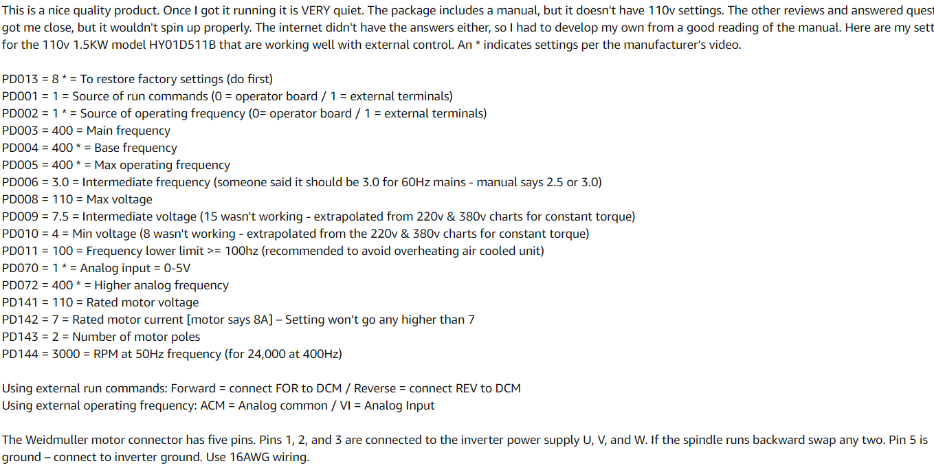
The C3D spindle does not run at the advertised speeds. So for a 3rd party you would likely need to contact the supplier. Hopefully you speak Mandarin to get any support. Seems like the advertised speeds are never what is advertised. You may need to figure out the percentage of change and make custom tools by copying existing tools into a custom database and changing the speeds for the tool to get the exact tool speeds. However the speeds are pretty close and likely wont make any appreciable difference when running. But if you want to get it exact I think the custom tool database may be your only option.
Its not a C3D spindle, it came with the kit. Its probably the same Chinese supplier. I wonder if there is an incorrect setting on the VFD or like I saw in another post the output voltages on the PWM out aren’t accurate.
Did some testing with the VFD parameters, whatever I changed didn’t have an effect on the RPM’s. However I did check the voltage output of the PWM signal. at 12k rpm I was getting 2.5v, at 24k - 4.9v and at 8k - 1.72v
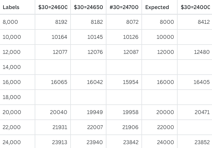
Made a small workaround for this issue. Set $30 to ~24650 and now 12k rpm is almost spot on. Other rpms are now within a 100-150 variance. Even 24k is still at about 23800. I think this is about as good as its going to get, probably wont make much of a difference when machining I hope.
In the controler there will be some settings that adjust what max input = max frequency. You can adjust this down to match the input. It will however skew all other inputs up slightly. My controller is different, but for example:
Mine is set to 5v, and my board puts out a true 5v @ S24000 with $30=24000. I believe my controller is set to 1020 which yields me 400hz output or max rpm. Look through your VFD manual settings and you should see a similar option. You can also set a minimum which will shift the entire thing up. All you are doing is adjusting the scale of output based on 0-5v (in this case) input.
As an aside, if you watch the controller you can see what Freq is being output and that will tell you the RPM +/- the variance of the motor specs. RPM = Freq * 60.
I saw your comment on my post, I will check my board version # tomorrow when back in the shop.
I looked through the manual for the VFD and there is no option to change analog input level other than 0-5V or 0-10V. For now the best I can do is skew the max RPM in the GRBL settings to bring the other values closer. A $30=24650 seems to be the sweet spot with low RPMs being a tad on the high side. I doubt I will be running much at low speeds. I’m waiting for a response from C3D if I can get a replacement board with a true 5V output. Seems like the voltage regulator on the board is bad.
So I checked the SMD voltage regulator. I’m getting 24.0v on the input pin and 4.91 on the output. With 24v being supplied to it there should not be any dropout, even with no load. So I either need a new board from C3D or just solder on a new regulator.
PWM signal does not vary linearly with voltage. It is a square wave train that varies in width as the parameter value varies. It is often put through a low-pass filter to get a voltage signal level by a receiving device but it will never read Vmin or Vmax because then there would not be a pulse wave modulation. The signal receiver either has to have adjustments for voltage range levels or use the actual pulse edges to follow the modulation width to allow for accurate calibration.
The way to actually check the PWM is with a scope to see the waveform pattern & measure how the width of the pulses changes with the specified RPM value.