Imagine a swimming pool with a deep end and a shallow end. There is a gradual sloping transition from the deep end to the shallow end. How do I define this in Carbide Create? Do I need to design it in Creo first then export a .dxf file?
Carbide Create can’t do that in the free version.
Pro can do it — if you have difficulties, let us know the dimensions and we’ll work through it w/ you.
Probably this sort of thing would be better in a traditional CAD program paired w/ a 3D CAM tool — we sell Alibre Atom Workshop which would address that.
Free options would be FreeCAD, or Blender.
Are there any good tutorials I can watch to learn this? I just purchased a Pro license.
If you’ll let us know what dimensions you’d like to cut, we can prepare a custom tutorial.
Ok so I’m designing a cavity mold for an rc plane component we’ll be making from carbon fiber. The base material is aluminum. There is a rectangular pocket 500mm X 50mm carved to a depth of 10mm from the top of the base material. To the right of that there is a second rectangle 50mm by 23mm and carved to a depth of 25mm from the same top surface. Both rectangles share the same long axis. The base material is 50mm thick, 650mm long, and 75mm wide. There is a slope downward from the larger rectangle to the smaller, deeper rectangle on a 55 degree angle. All vertices assume a 5mm radius.
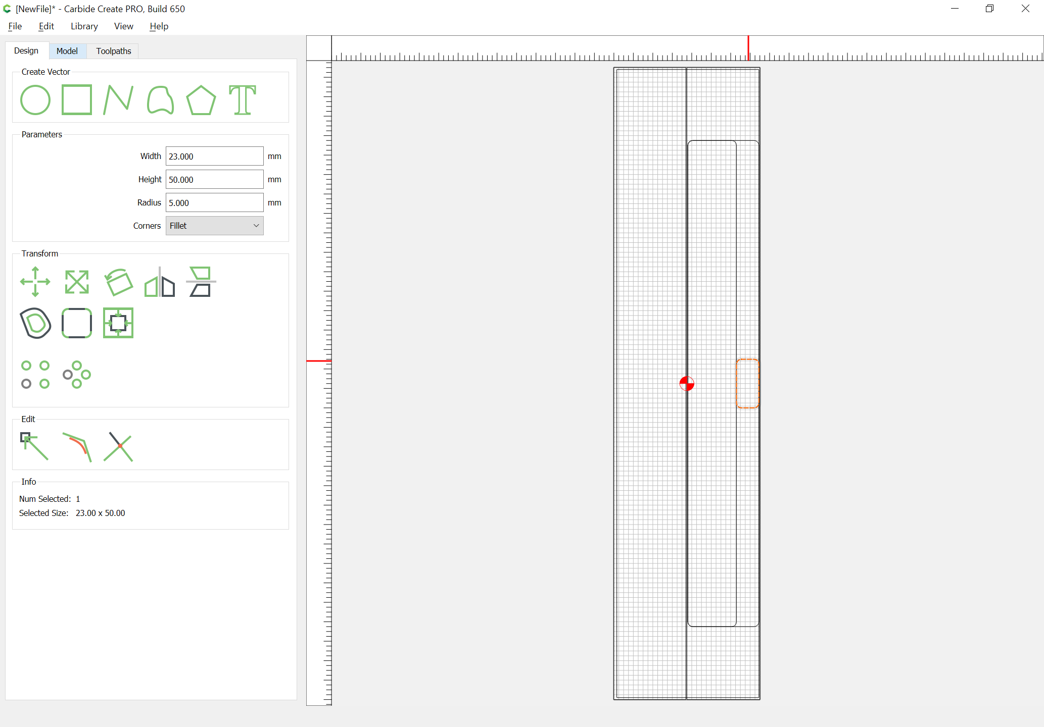
Okay, let’s start w/ the Stock setup:

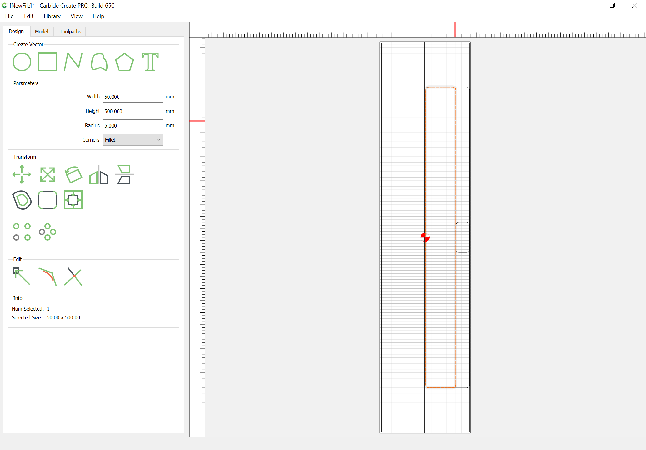
Then let’s draw things up in profile:
Where is the 55 degree angle supposed to be?
There’s an issue with the rectangles. The large rectangle seems fine. The smaller rectangle should be shorter and narrower. The two rectangles should share the same longitudinal centerline. The 55degree slope should bridge the depth of the two pockets.
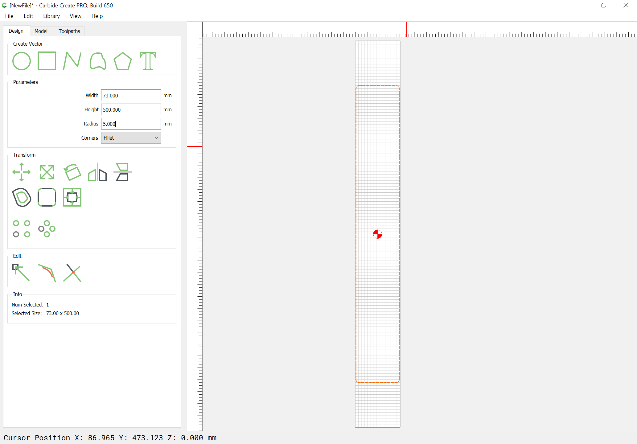
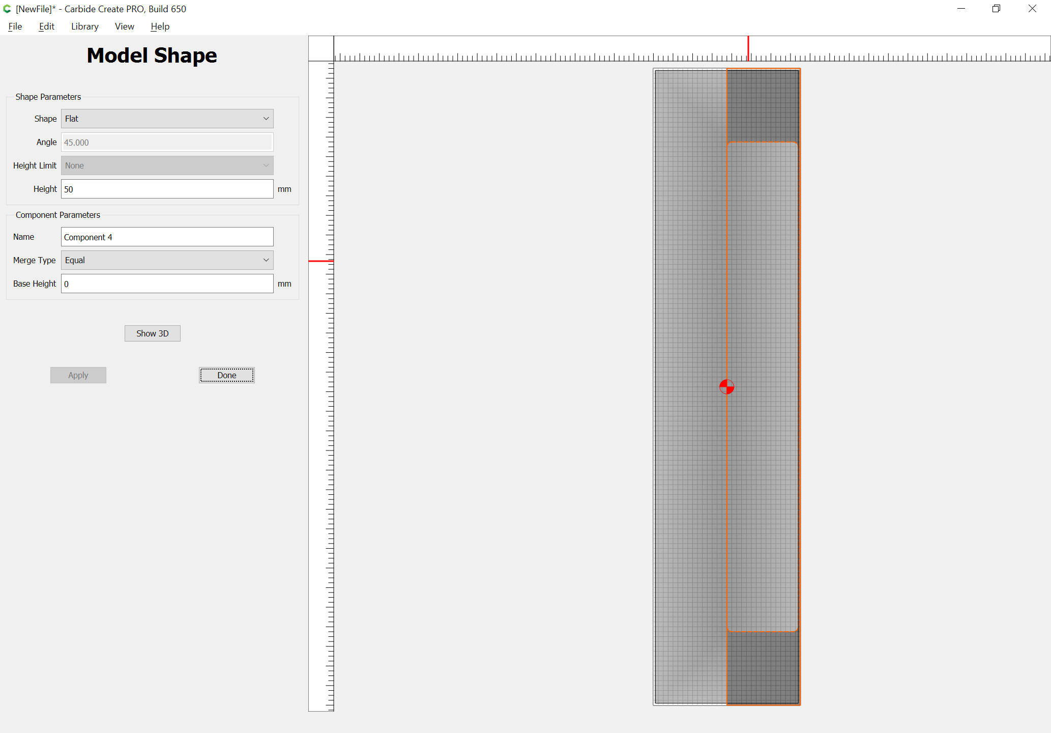
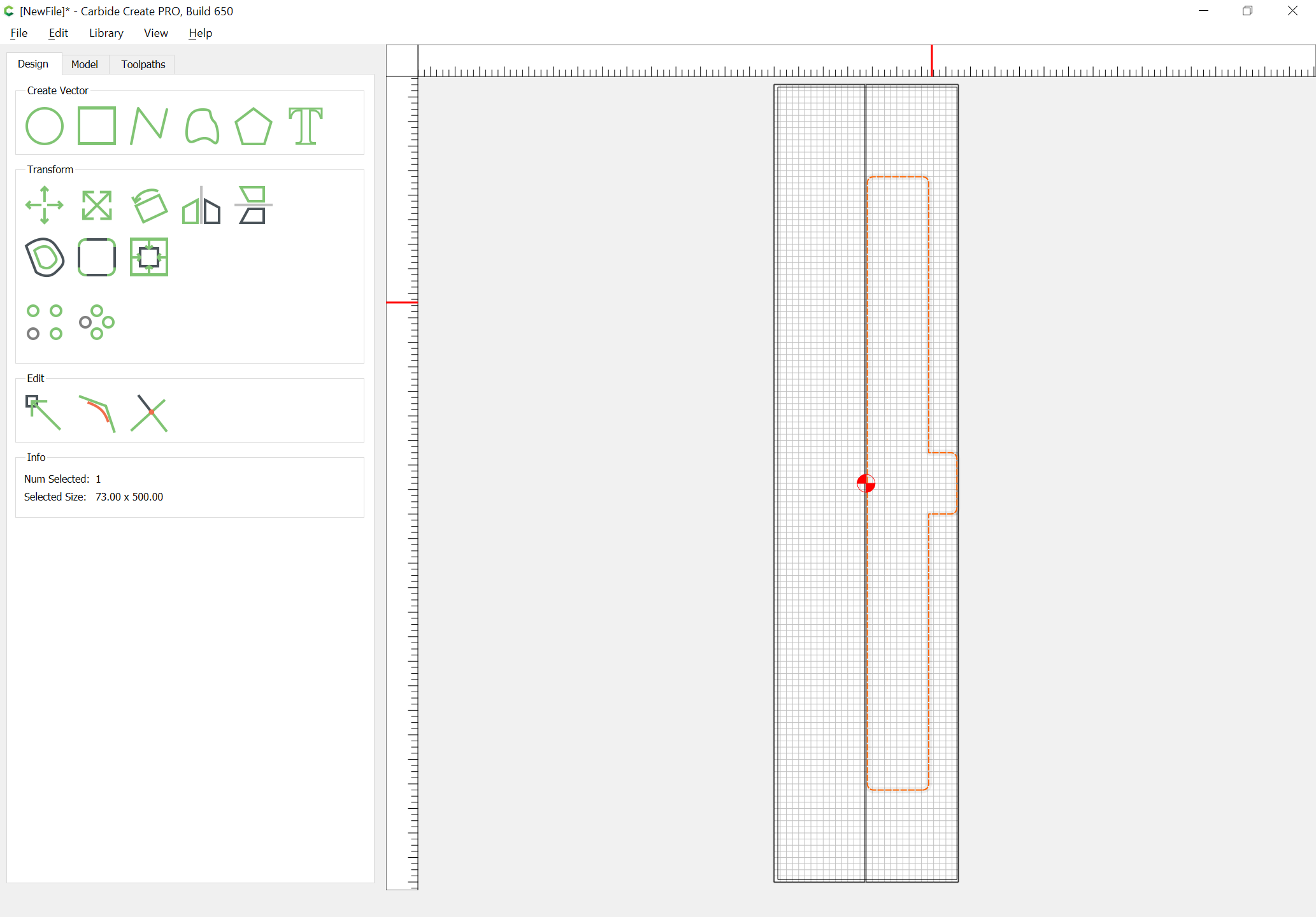
If we assume that we want a 73mm wide rectangle which is 10mm deep on the left side and 23mm deep on the right, then we would draw in the overhead view:
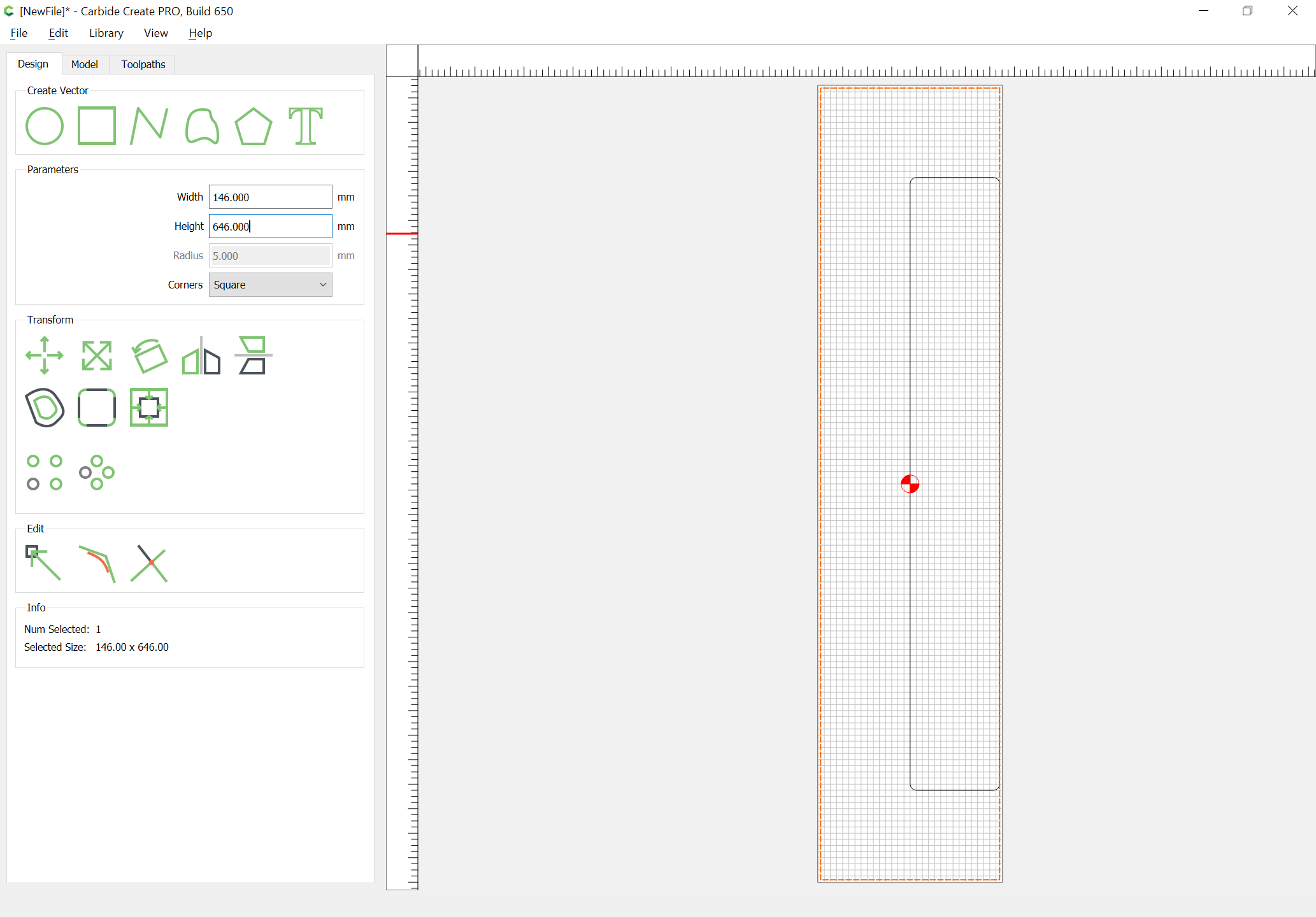
and then draw in a squared off rectangle which is twice as wide and adds twice the width of the original to the height:
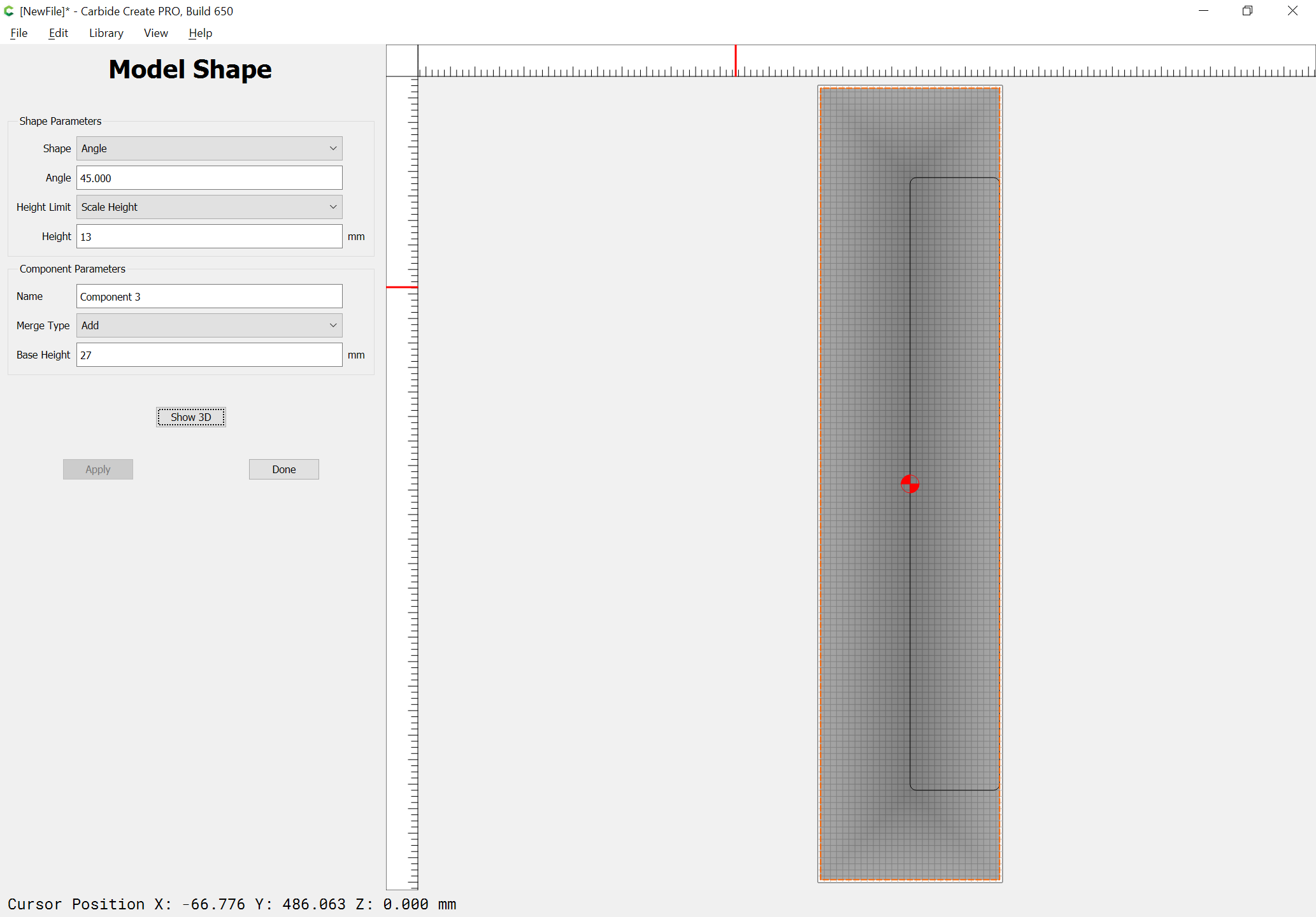
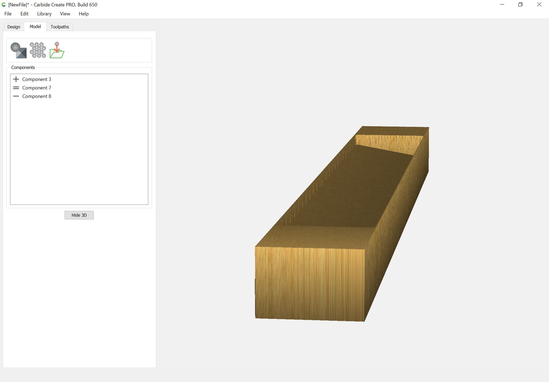
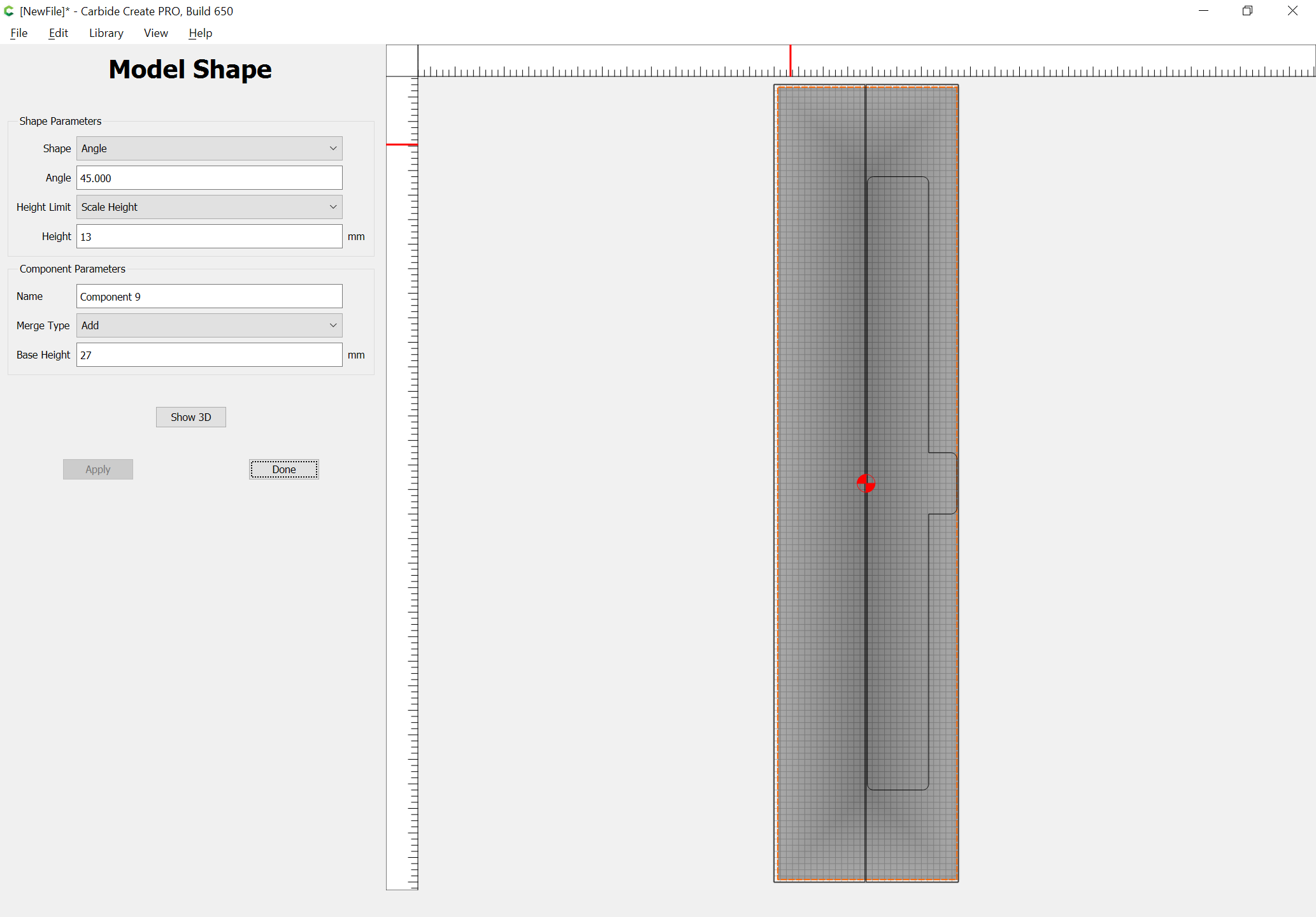
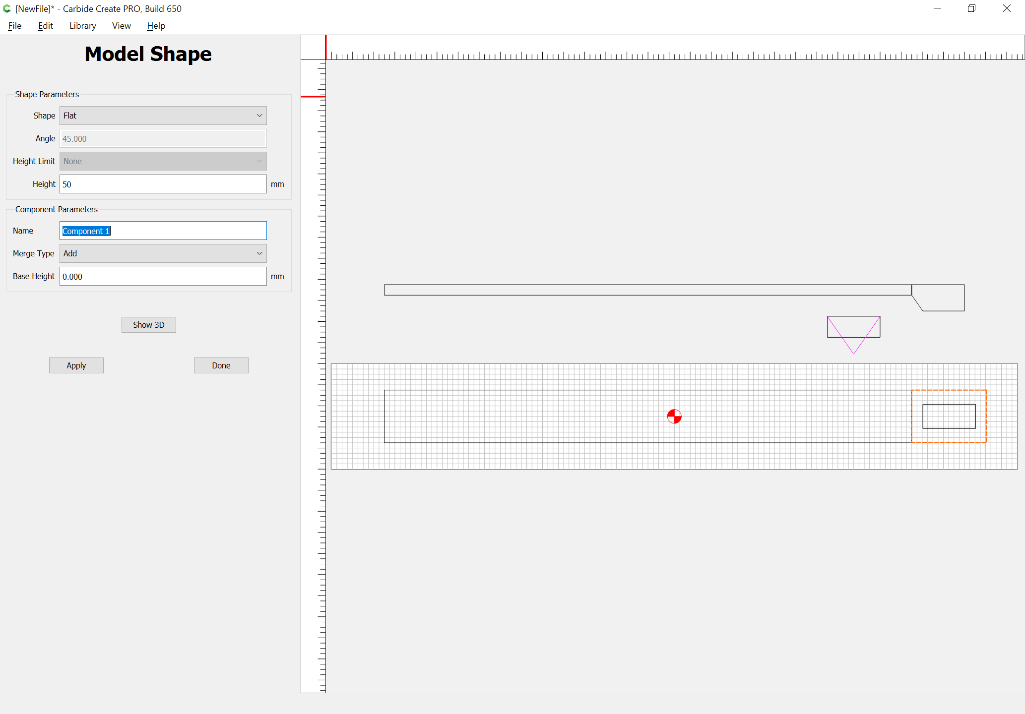
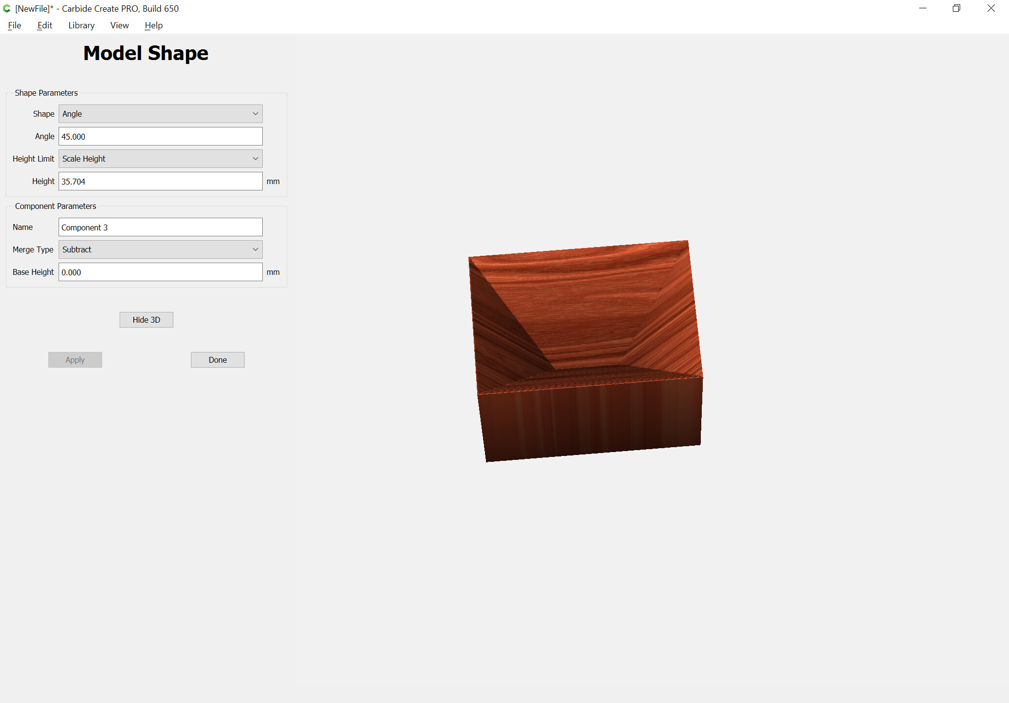
and model it in 3D after going back and adding doubling the width of the stock:
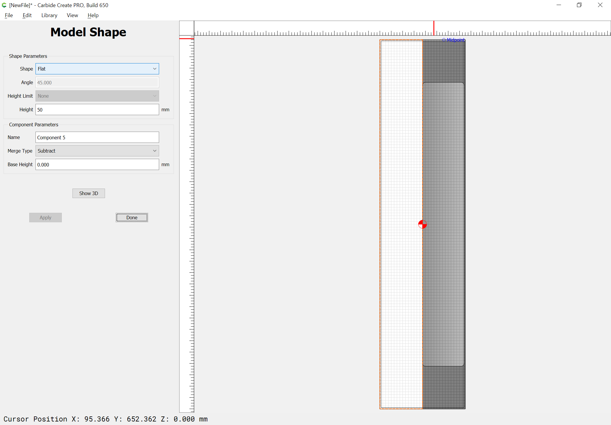
We then add in the surrounding stock:
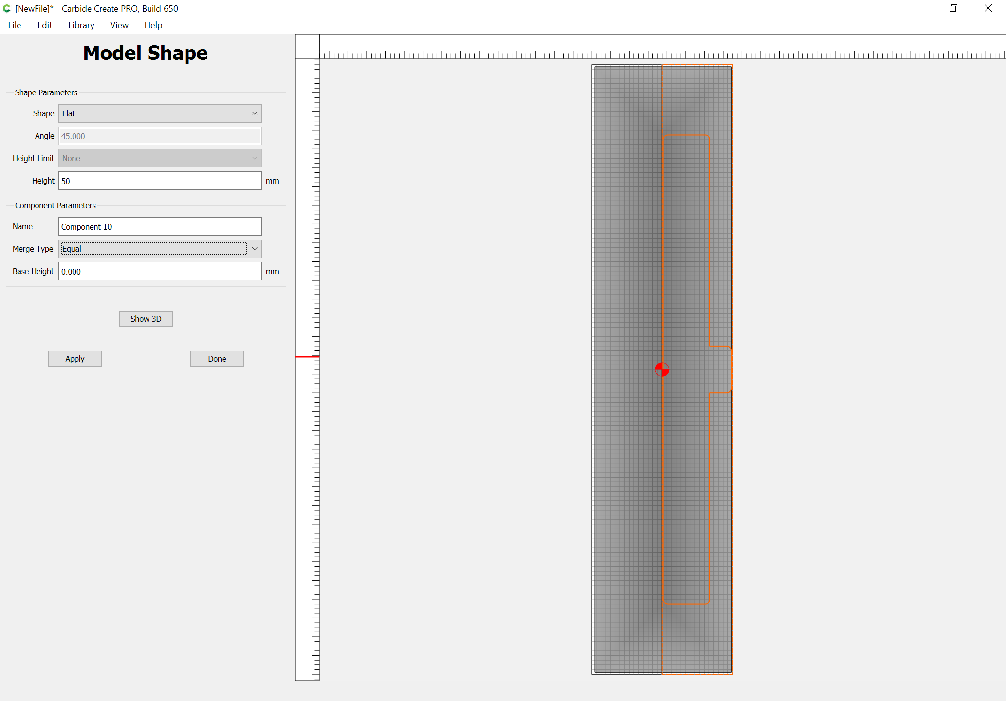
and remove the extraneous material to the right:
which models as:
Could you post a 2D drawing?
I’m puzzled:
Where’s the 55 degree angle?
Do you have a 3D CAD or drawing?
The same modeling technique would work for the two rectangles — just extend the one on the right and Boolean Union them:


Here’s snip of the mold I’m trying to create. It won’t allow me to upload at step file. Does this help?
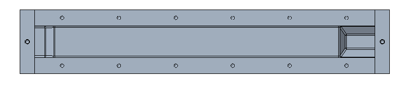
A side / section view with a few dimensions would help more. What’s happening on the left end there?
I think I see what you were describing now. The 50x23 is the bottom of the “deep end”, not including the angled walls. ?
You should be able to follow Will’s process, just adjust the dimensions to suit.
1 Like
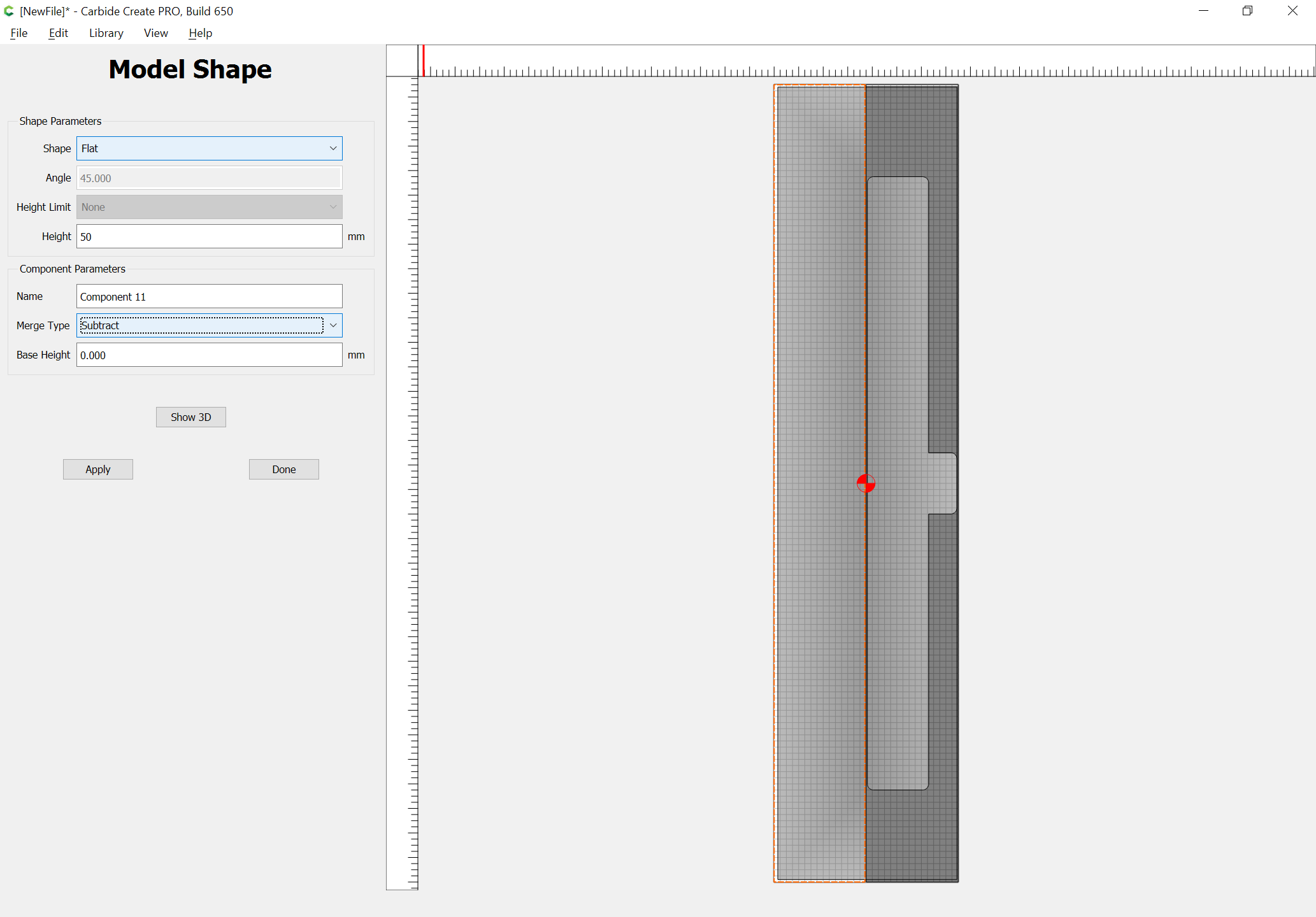
That should be feasible — something like:
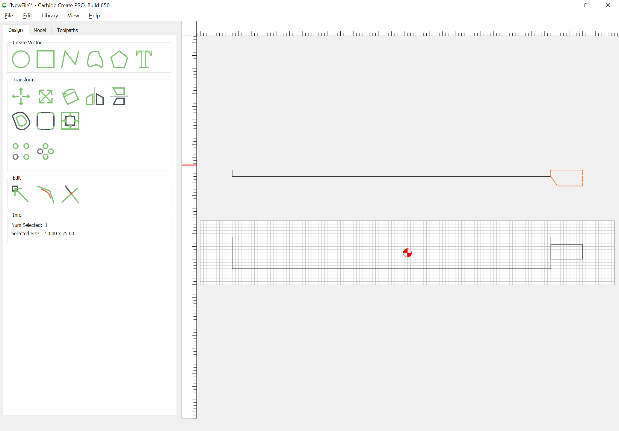
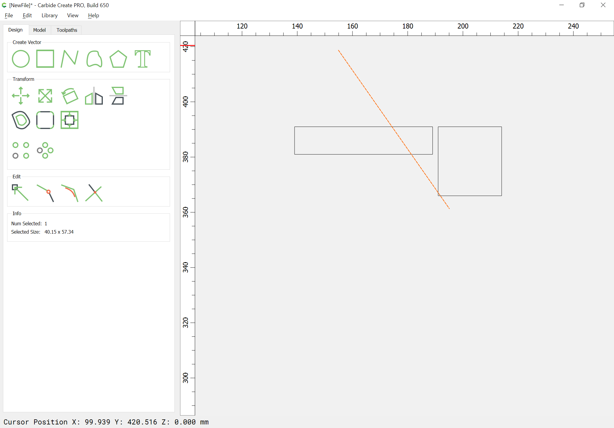
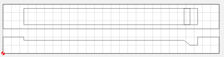
Draw things in profile:
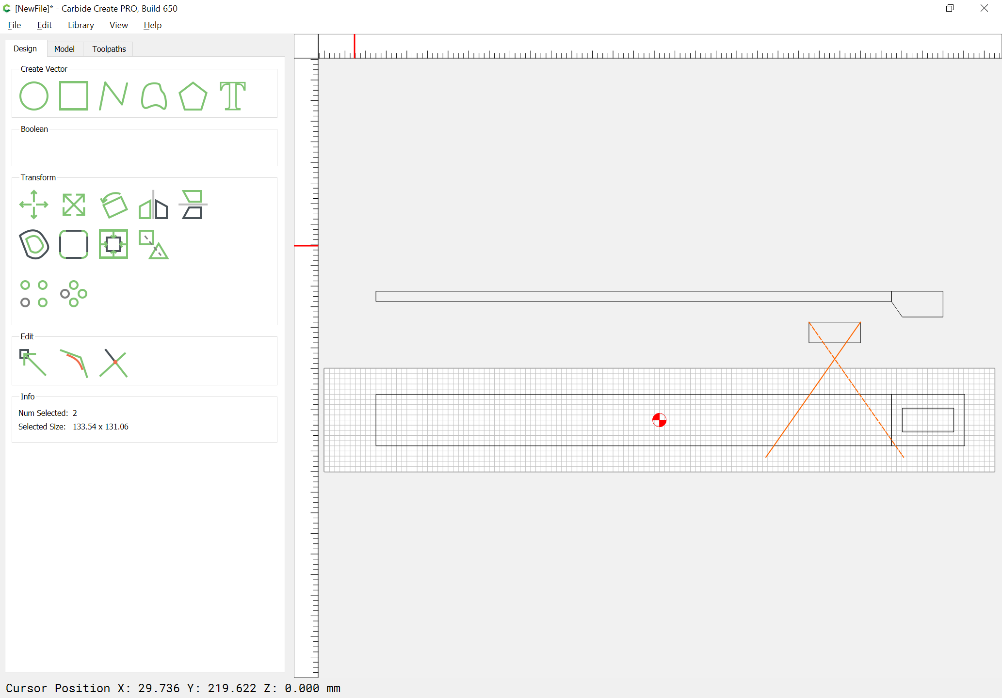
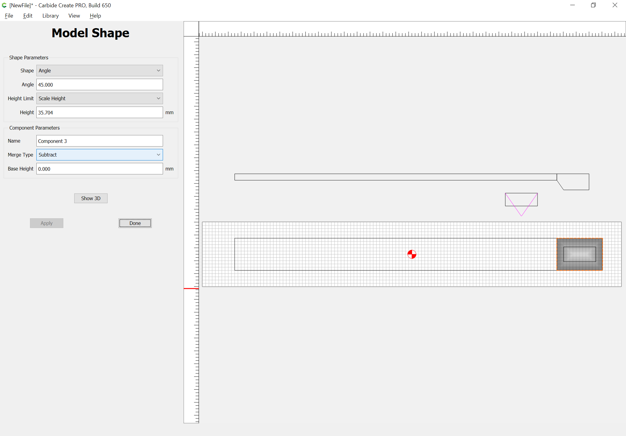
and use Trim Vectors to get the intersection:
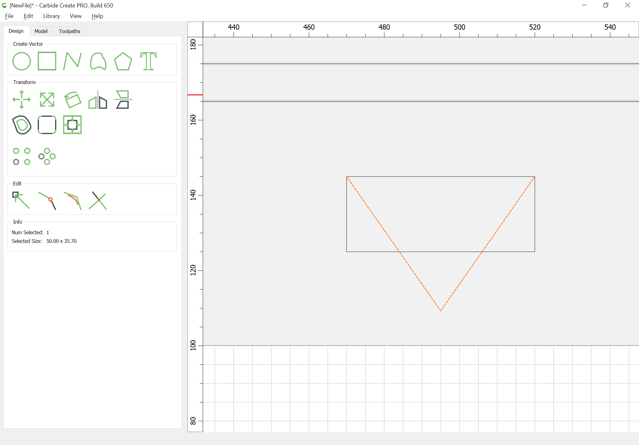
to then get the depth which things need to be cut away at:
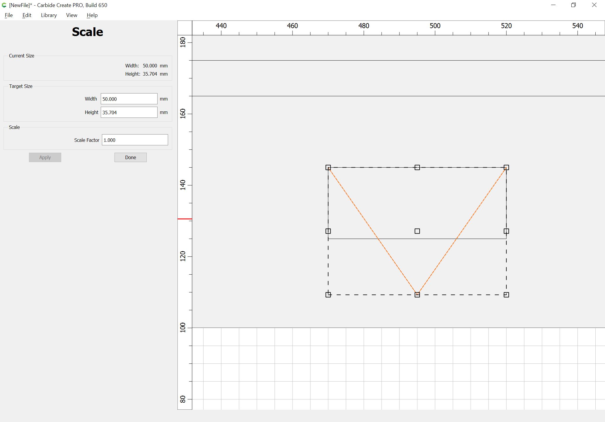
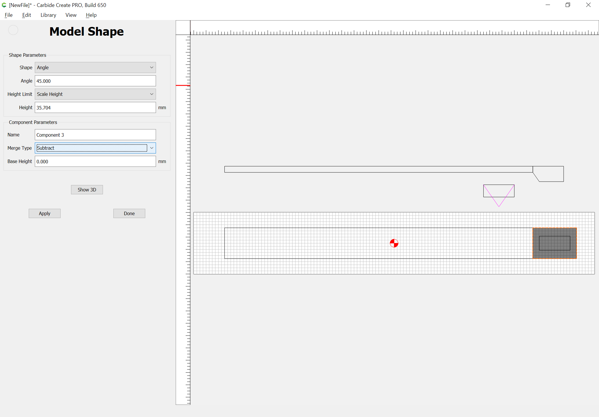
The balance should be obvious.
This topic was automatically closed 30 days after the last reply. New replies are no longer allowed.