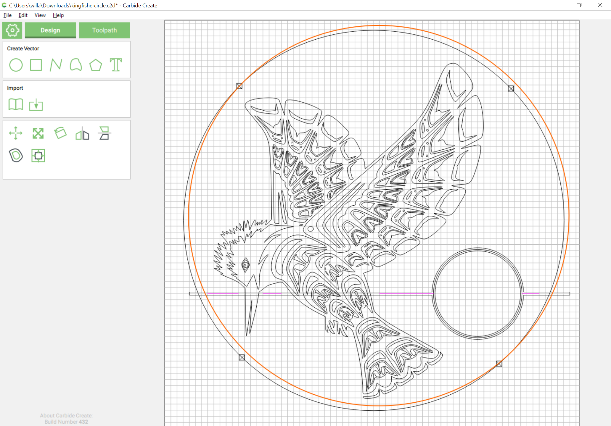
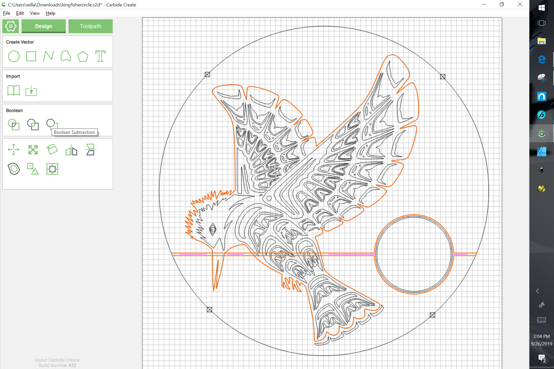
In carbide create, it’s had no problem carving out this bird before. But when I try to insert a circle and some lines to mimic a horizen with a sun, it wants to carve out the cirlce and lines like I’m using a 1/2" end mill or something. When I run the toolpath under Vcarve, it just carves out a tiny 1" circle in the middle of the sun and no horizen lines that I simply made with the line drawing tool. When I switch to contour and use the Vbit, it shows in the simulation like it’s a wide end mill bit for some reason. Is the simulation just wrong or am I doing something wrong that I’m not thinking of ? I simply want a dainty litttle vcarve line around the circle and the horizen lines. I’ve tried switching to other v bits, doing offsets in contour, etc.
V endmills only work correctly using a V carve toolpath — you’ll need to outline the strokes in question to create a set of closed paths which may be used for V carving.
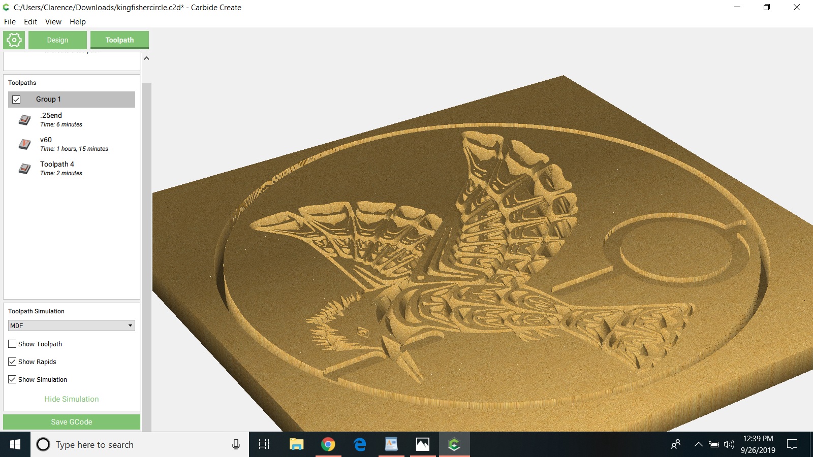
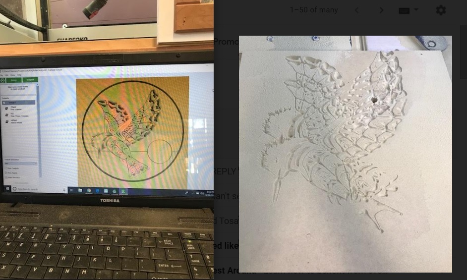
the picture shows what happened to the sun and horizen lines when using the Vcarve toolpath. I have a 60 degree vbit chosen and when I select the sun and horizen lines, it shows a huge wide gouge. It’s like it thinks that I have a 1/2" endmill or something chosen when I tell it to vcarve out those specific lines in the vcarve toolpath.
kingfishercircle.c2d (1.1 MB)
Right. As I noted, V endmills are only used correctly for V carving toolpaths. They are previewed as if they have their max diameter as square endmills if not used for a V carving toolpath.
I guess there’s something I’m not understanding. I am using the vcarving toolpath with a v bit…
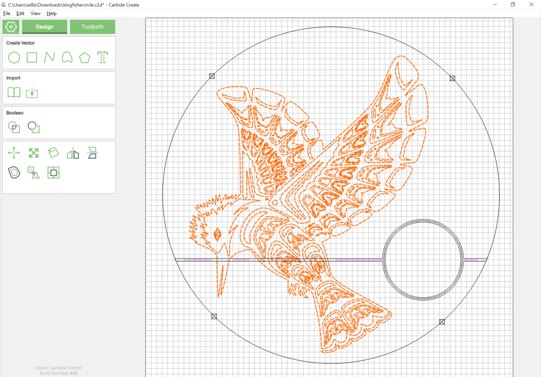
To fix this:
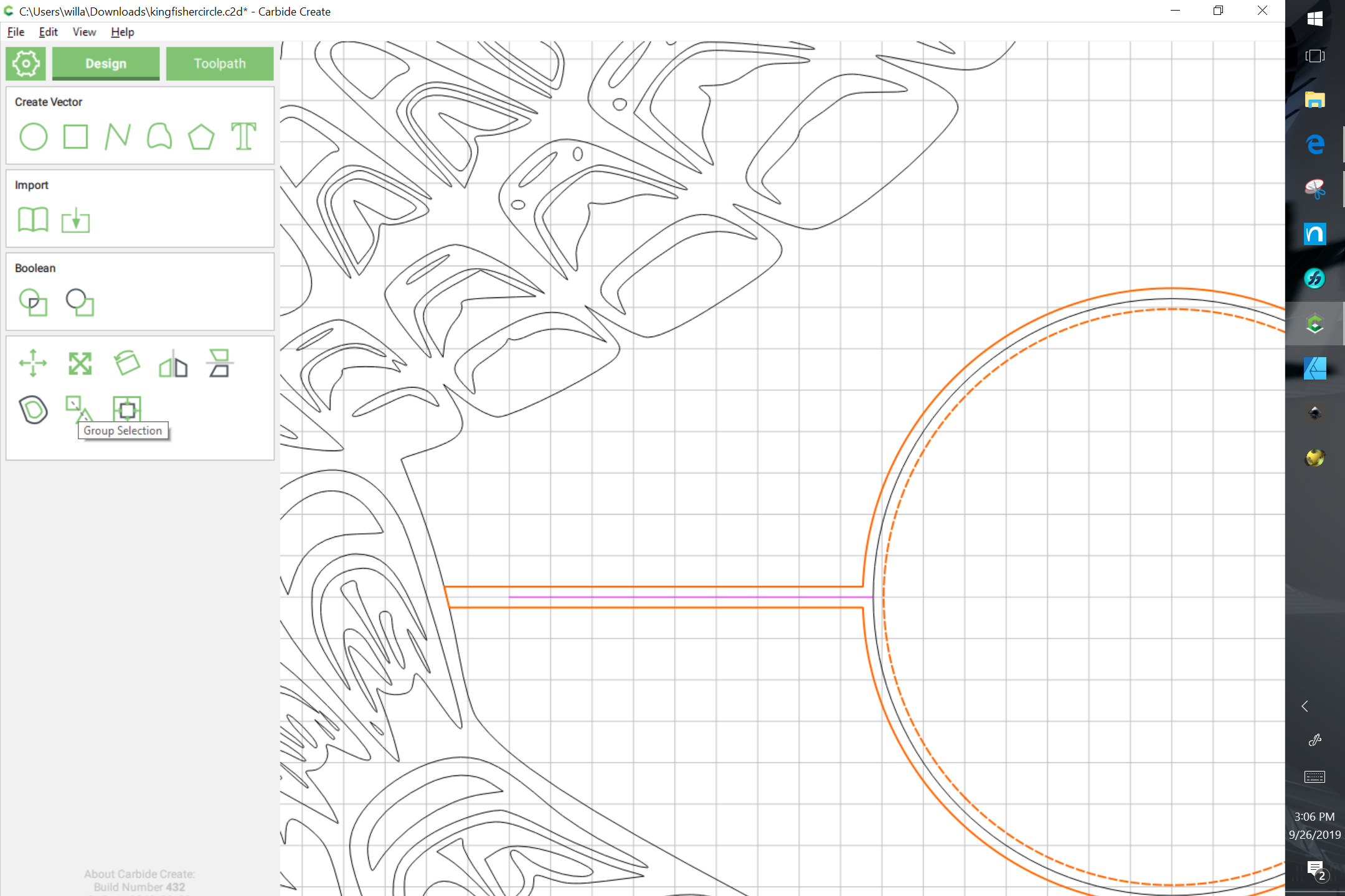
- open the file in Carbide Create:
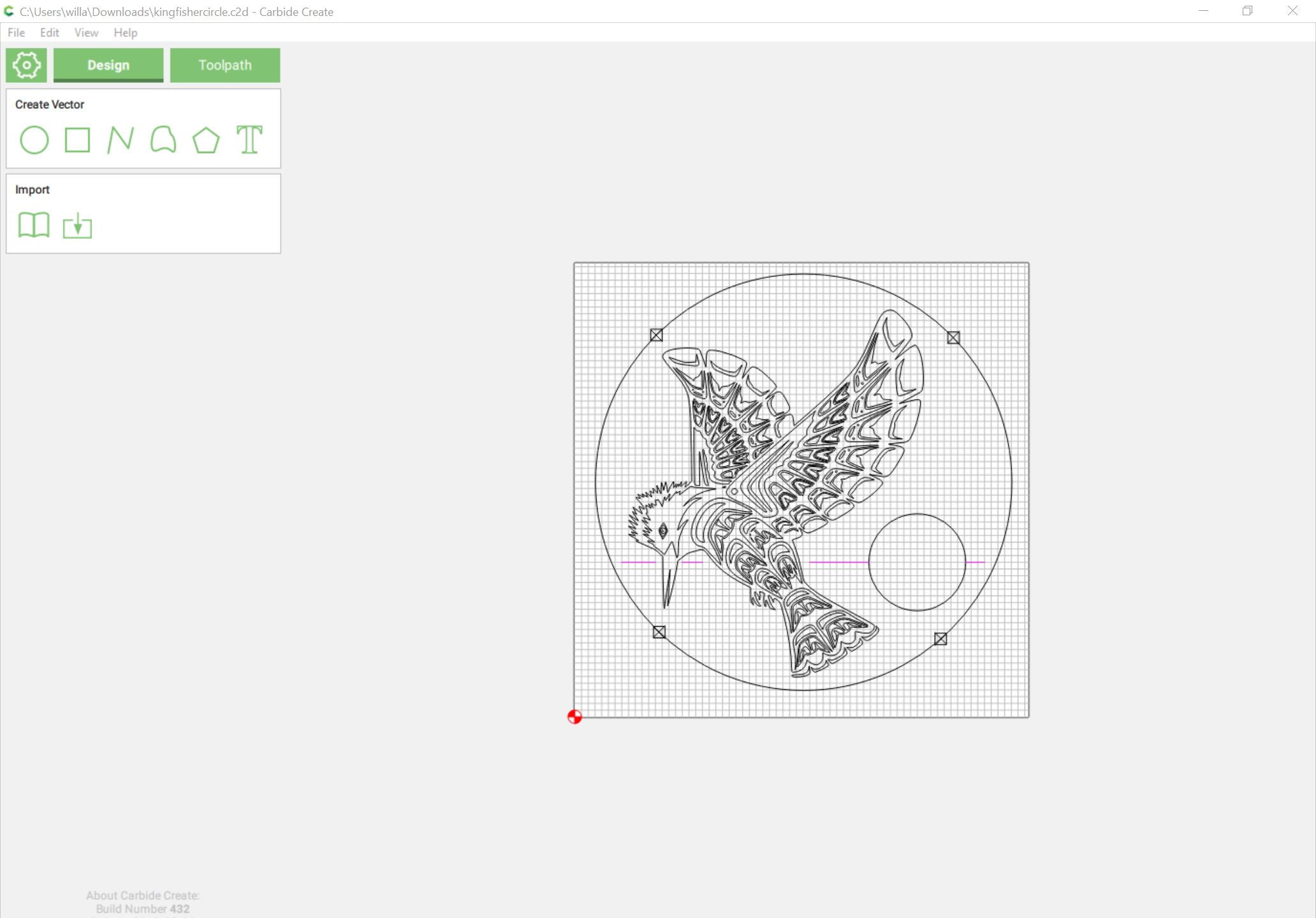
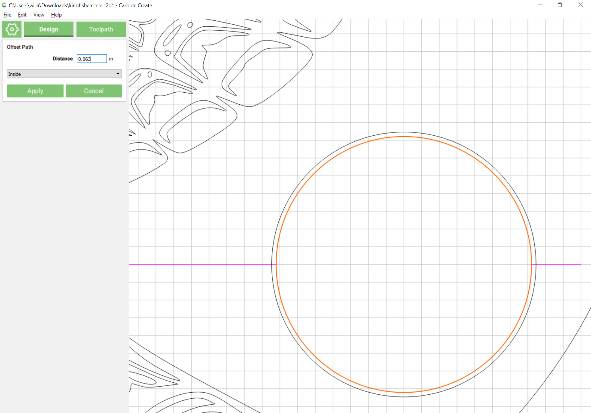
- select the circle:
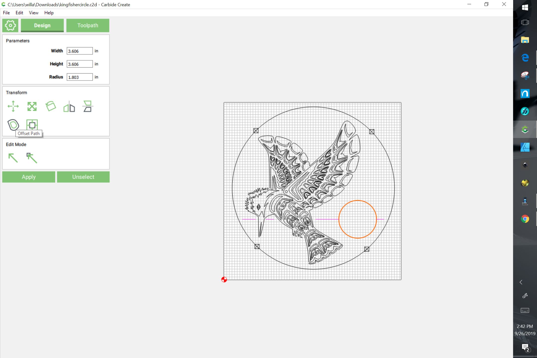
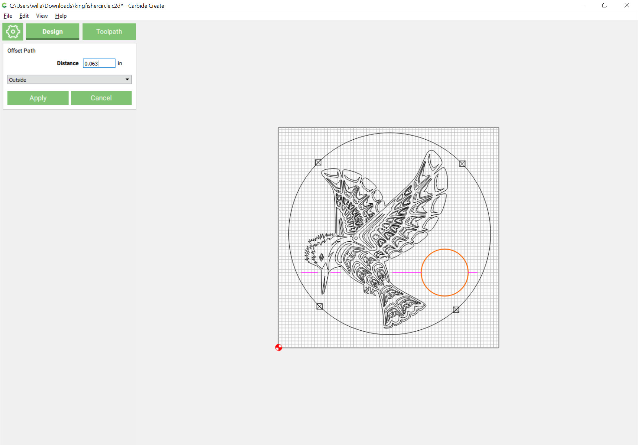
- offset it to the outside by half the desired width (we’ll use 0.063 inches):
- select the original and inset by the same distance:
- draw a rectangle centered over the lines:
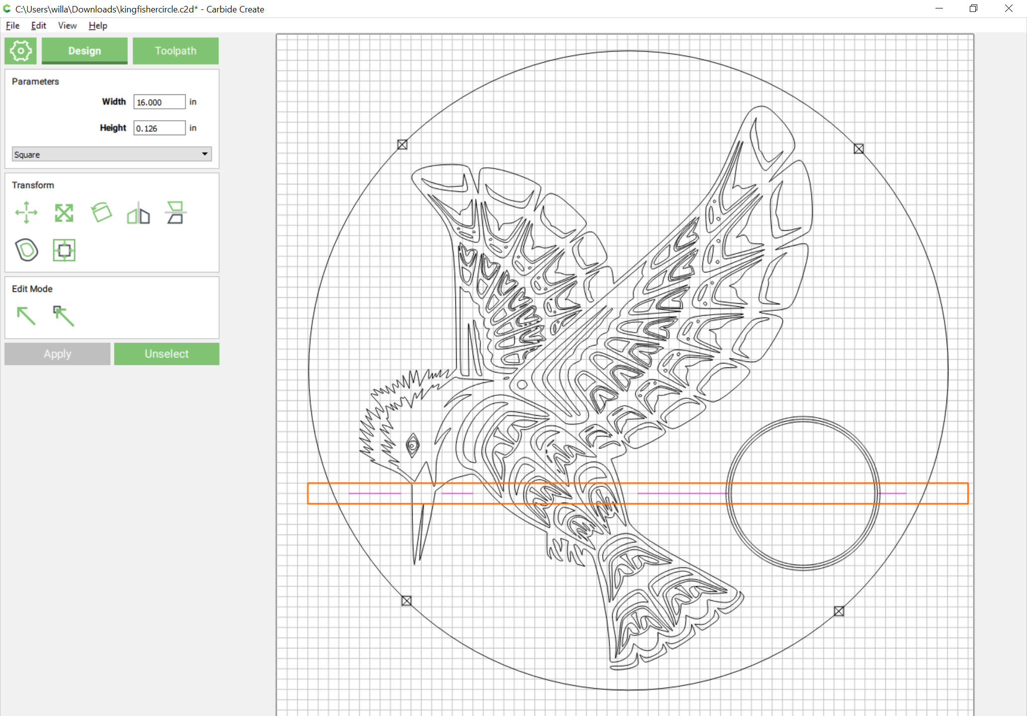
- set its height to 0.126in:
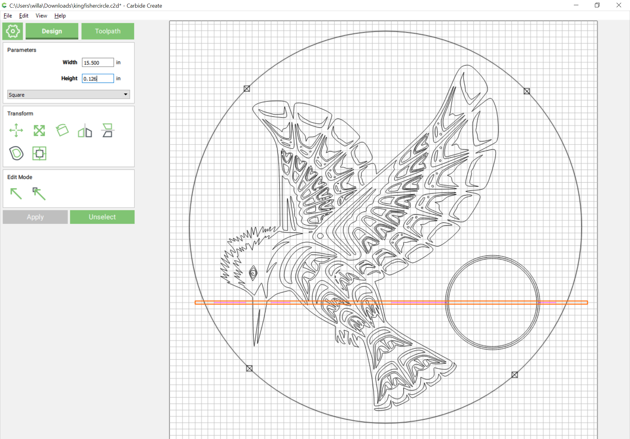
- shift click on the outer circle to add it to the selection:

- and do a Boolean union:
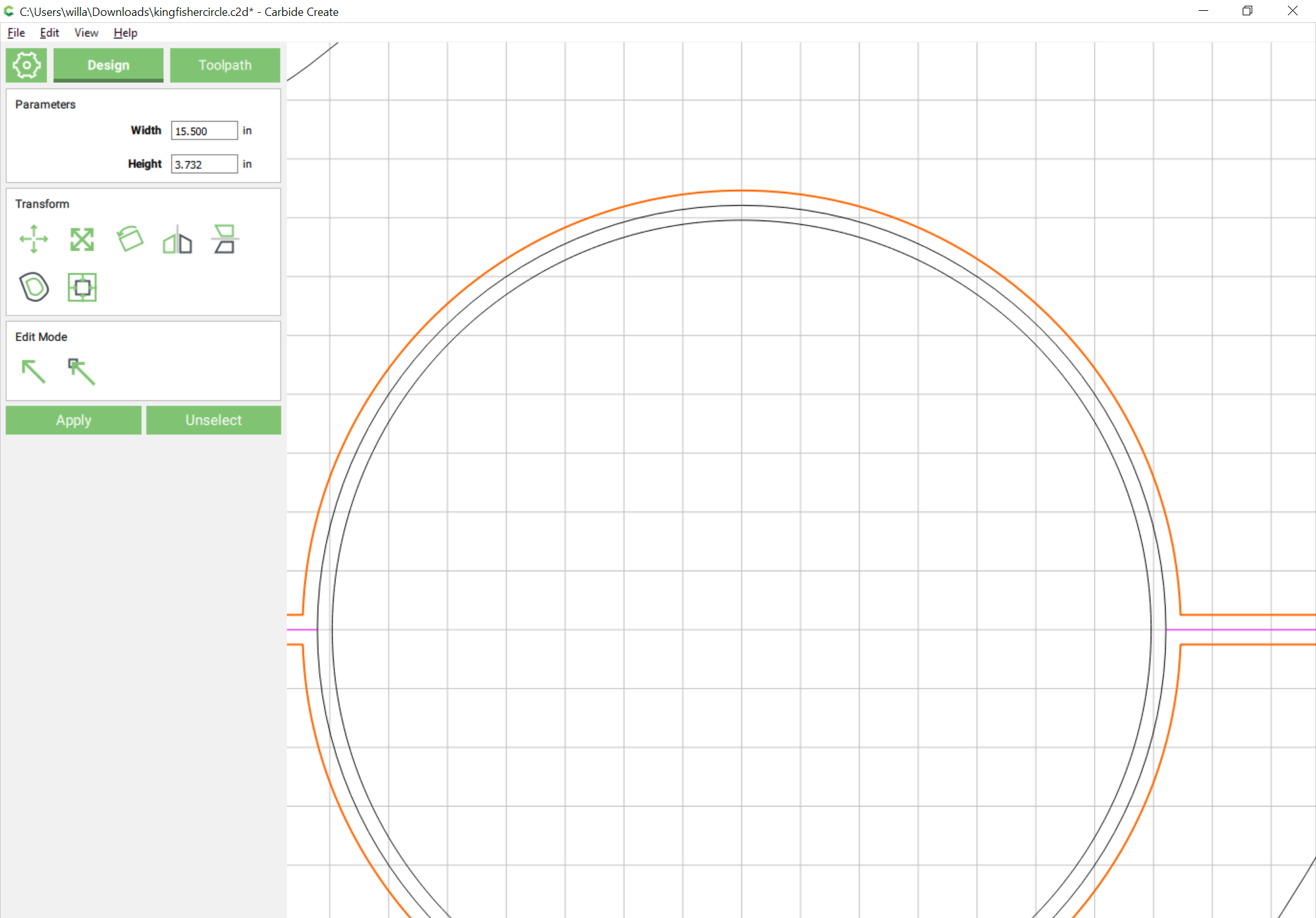
- select the outer circle:

- control c to duplicate it:
- drag it into alignment with the original:

- shift click on the circle-rectangle to add it to the selection:

- and do Boolean intersection:

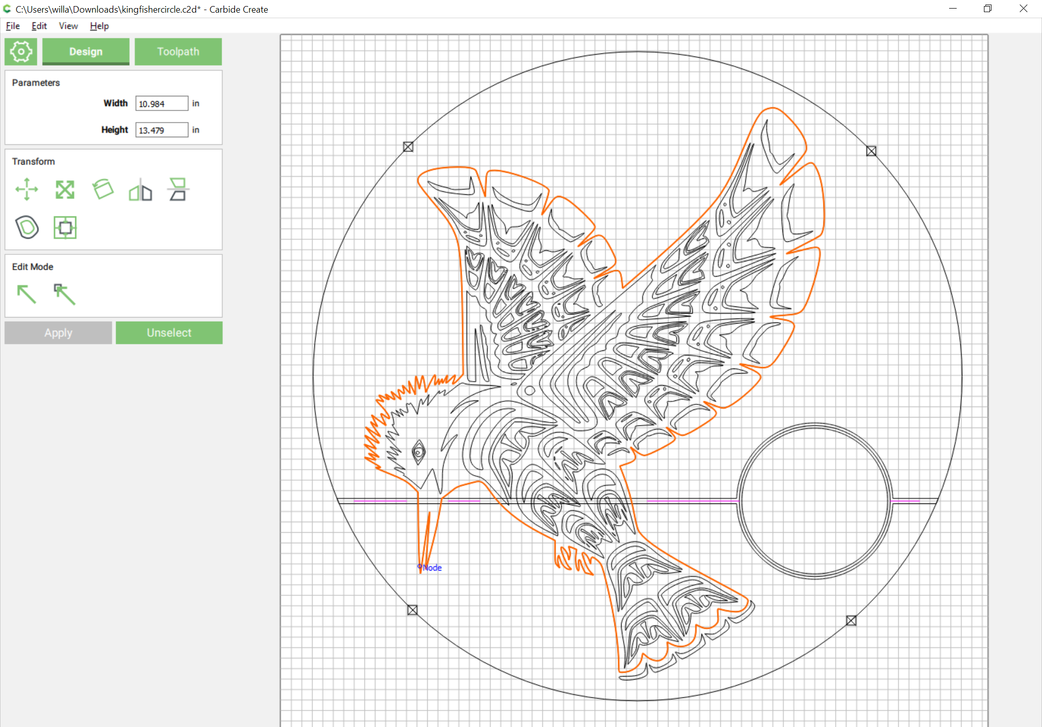
- select the bird:
- control c to duplicate it:

- note that this ungroups the duplicate of the selection — shift-click on the outline of the bird to remove it from the selection, then delete:

- drag the bird outline back into register with the original:
- select the circle-rectangle:
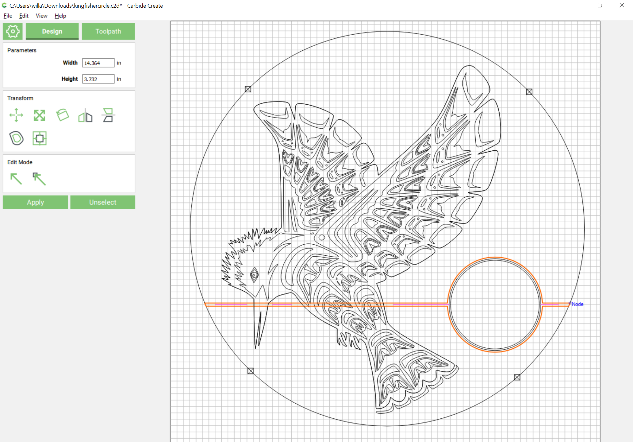
- shift-click on the bird outline to make it the key object (indicated by a dashed highlight) and add it to the selection:
- then do a Boolean subtraction:

- shift-click on the inner circle:
- for convenience group the selection, then switch to the Toolpath pane and delete Toolpath 4 and then assign a V carve:
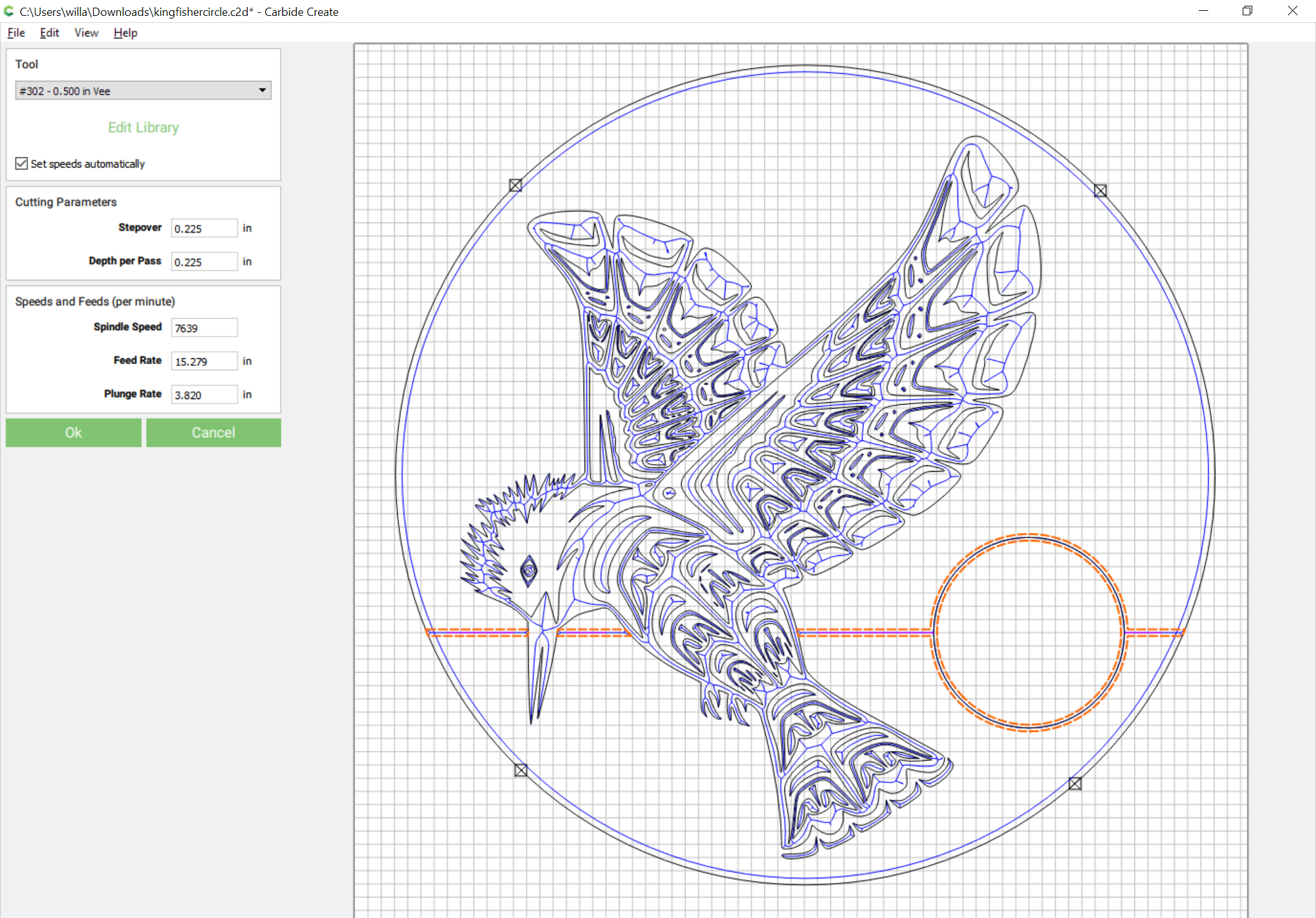
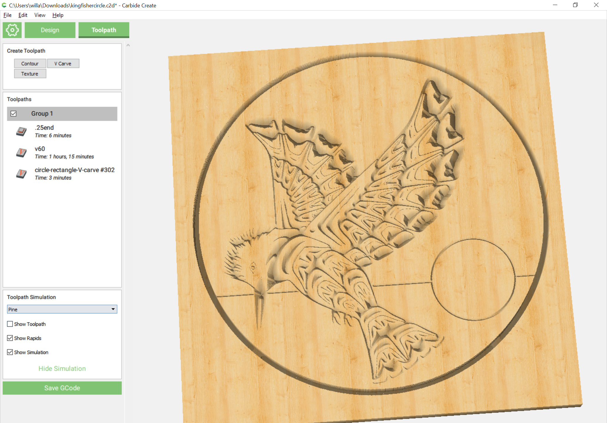
- which should then have the desired appearance:
WOW. That was way beyond what I thought the problem/solution was. That’s amazing. Thank you for holding my hand through that. I had no idea the complexties of using all 3 boolean tools. Is there a comprehensive boolean tutorial out there so I can gain the full extent of how to manipulate it ?
That’s pretty much it.
See: https://docs.carbide3d.com/assembly/carbidecreate/video-tutorials/#boolean-operations
The problem is Carbide Create’s handling of Boolean operations doesn’t respect grouping, so some things are more complex than they would be if groups were treated as compound paths are in other tools.
CC432 version: kingfishercircle_Vcarve.c2d (1.4 MB) — for 432 see: https://carbide3d.com/carbidecreate/unstable/
any ideas on why this might have happened ? the material was screwed down so no shifting took place.
Lost steps.
Check the machine mechanically:
- Pulley set screws: http://docs.carbide3d.com/shapeoko-faq/shapeoko-3-how-to-check-the-pulley-set-screws/ — be sure to check all axes/pulleys including Z.
- V wheels / eccentric nuts: http://docs.carbide3d.com/support/tensioning-eccentrics
- Belt tension — the Z-axis should be guitar string tight (but careful not to bend the motor shaft): http://docs.carbide3d.com/assembly/shapeoko/xxl/step-5-belting/ on deep cuts it may help to remove one spring from the Z-axis temporarily, esp. if one hasn’t added a spoilboard on top of the wasteboard — it also helps to install the router as low as possible (installing the Makita adapter upside down will help). Some folks have found it helps to remove bolts which won’t stay tensioned (M4 Z-axis tension bolt, various V wheels with eccentric nuts), apply a thin bead of threadlock along the length of the threads, then reinstalling. See the video at: https://www.youtube.com/watch?v=_lIIb_PdziA Note that the X-axis motor is held in place on standoffs and if those bolts are loose this can cause belt tension issues.
everything is tightened. Router mount screws were both loose so hopefully that was the thing, some of the y and x mounting rail plate screws were also loose. Here’s hoping that’s the problem.
Quick dumb question, can the carbide touch probe be used for vbits ? Everyone seems to have differing views on this matter
Yes, one can probe for Z (only, with the Probe fully on the stock) with a V endmill.
You have to probe for X and Y (and Z if doing all three) using a supported endmill size.
An issue that’s been happening now is the z axis is plunging further into the material than it should. When I had the problem with the loose screws last time I tightened everything. The only thing I can think is different is I installed a suckit dust boot, which of course requires new bolts to the Z axis plate. Those are all tight. I has the 1/32 square endmill installed very tight with a max depth of 1/8" and It’s almost going past 1/4" now into material. Right as I stopped the operation yesterday with the two birds carving that had messed up, it just seemed to get a mind of its own and started plunging straight down through the material and through the bottom with the 60 degree V bit. The strange thing was it wasn’t slipping, it was a controlled slow plunge like it had programmed itself to just keep going down till it couldn’t anymore. Is this common ?
Usually when this happens it’s caused by a disconnect in how one has the origin set in the file and how one is setting zero relative to the stock and the maximum upward travel of the machine.
Post the .c2d file, generated G-Code, and a step-by-step set of instructions on how you are securing your stock and setting zero relative to it and we’ll do our best to help you puzzle things out. Or e-mail the same to support@carbide3d.com
I completely forgot about having the probe all the way on top of the stock with the Vbit. I feel dumb for forgetting that but at least your reply reminded me of it. Thank you.
This topic was automatically closed 30 days after the last reply. New replies are no longer allowed.