Vcarving too deep and design question

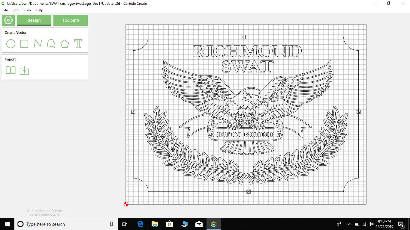
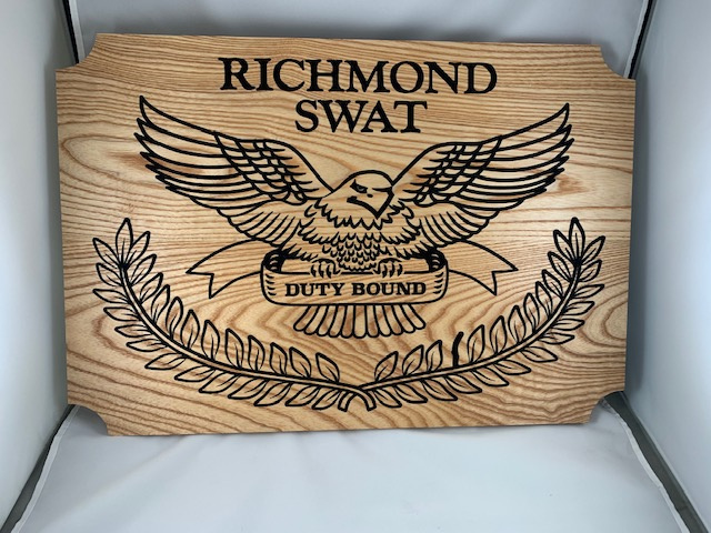
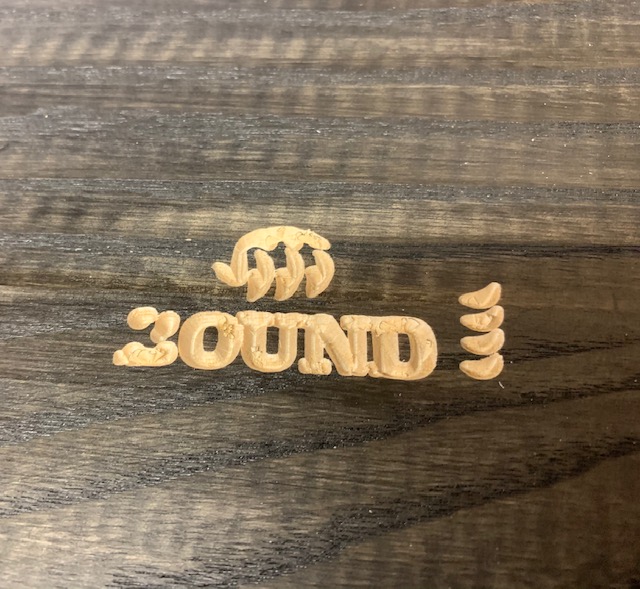
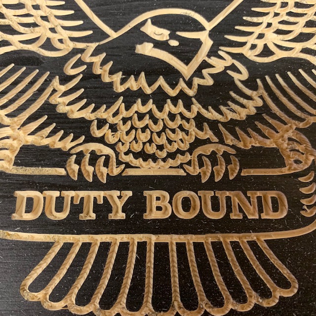
Hello all. I have a logo that I had redrawn by a graphics design person. I use inkscape to open it. I have entered it directly into carbide create. The logo is not drawn as single lines put as dual lines for all artwork. I assume they did this to allow it to vcarve? Here is the problem I am having. I first attempted to cut the logo, zeroed on top of my board with paper test, and right off the bat it is cutting too deep. So that leads me to believe it is because of the way it was drawn with the dual lines of everything. So, after wasting a lot of wood, I did paper test, then raised bit substantially and ran it and it turned out great. This was 2 months ago. I went to cut this same design again last night, thought I had learned my lesson, paper test, raised bit .55 mm above stock and set zero, started cut and boom, a wasted piece of wood, cut too deep. I probably needed to go up another .4-.5 mm to have been close to being right. So, is my problem with the way it has been drawn with these 2 lines, thus, based on how far apart they are the bit is trying to go deep enough to cut it? Am I going to have to have it redone again and make the space between lines smaller? Or will/can I have it redone with single line only? This is really frustrating me because I have a lot of requests for this piece and I am wasting a whole lot of time money and wood in 2 seconds every time I run it. I will add image shortly. Thanks everybody!


image

Hey @BOX5,

Just checking, about that second pic, did you mean to post the same one from two months ago, or the fresh one that went too deep and you mixed the images?

For V-carve to work as expected, in a deterministic way, you need to get a good understanding of how it works (which as you said, is basically is that the bit will go as down as it needs to go between two lines, so the depth will depend on the vbit angle. Sorry if this is obvious), and zero the bit on the surface precisely. Raising the bit by XX mm manually is not the way to go, it’s probably a workaround hiding another issue somewhere in your zeroing procedure or in your design file, so you’ll go nuts trying to guess which value is required to end up with a good cut.

Can you share your c2d file for a quick look ?
And confirm which V-bit you are using for the cut ?

Cheers

I will gladly share the file when I get home this evening and get to my laptop. I am using an amana 45624 solid carbide 1/4" 60 degree bit. I posted the original picture that I guessed and got lucky and it turned out good. I will post another picture of the one that messed up yesterday, although it won’t be much to see because I stopped it within 30 seconds of cutting because it was too bad a cut. And yes, I have already gone nuts over this, and I know what I am doing by guessing is not correct, but I don’t know why and how to fix it. I spent a day gluing up a nice piece of hardwood, sanding staining and then 20 seconds and ruined. Thanks for your help!!

1 Like

Ok! I’ll be asleep by then but I’m sure other folks here will jump in to help you figure this out.
Right now my guesses would be:

  • possibly an inconsistency between the actual Vbit angle, and the one you declared in CC
  • flatness/bow of your stock. I see you zero in the lower-left corner, if your piece of wood was, say 0.5mm thicker elsewhere, that would result is the V-carve being “too deep” there (and the next piece of stock may be more flat and work just fine, so that would appear as if the g-code file “randomly” worked sometimes, and sometimes didn’t)
1 Like

COREY SWAT RETIREMENT FLAG.c2d (1.1 MB)

In the first picture you see i stoped it very soon. If you look atthe letters you can see how they touch, the O even overlaps into the U, the N and D connect at top, etc. The second picture is better but still too close in the letters and in the eagle feathers right abpve the words you can see how it looks too deep. The first picture i did about .3 mm above stock. The second one I did .5 mm above stock. I’m not sure about the wood thing, because if that were the case, on the picture from 2 months ago that turned out good, it’s equal all the way around. In the second picture here, that I did last night, it’s equal depth all the way across the logo, not different depths in different areas.

Hey Mike when I looked at your file you have a #22 .250 bit selected for the logo? That is not the 60 degree v-bit. Also you have some double stars in there as well I get these as well on occasion not sure why, but you can see some of the stars are darker than the others that is one on top of the other.

1 Like

Unfortunately I can’t see the details of the custom tool you created for the logo V-carve. I guess that is a limitation of CC. It says “Amana 60 VBIT”, but are you sure you entered the information correctly? And is the bit really 60° or is it 59° or 61° for example? Also since you are using the paper method to zero, be careful not to dig into the material with the V-bit point, or you will zero too low. You should not have to zero way above the material the way you have been.

The #22 is a bit I installed. It is a 60 degree amana solid carbide vbit.
The double star I have never noticed but I will look into it. Where do you see it at?
Thanks

Thanks. I am zeroing well above the wood, which is not correct and that’s what I’m trying to figure is wrong. I am zeroing with the paper and then having to raise it .7-.9 mm to get it carving anywhere close to right. And yes, I entered the bit information in exactly as the manufacturer has listed.

Which version of Carbide Create are you using? This might be a long shot, but at one point I believe the V-bit angle was entered as half the Vee angle (e.g., a 60° V-bit would be entered as 30°). On newer versions it’s entered as “included angle” (e.g., a 60° V-bit is now entered as 60°). Could this have happened in your case?

2 Likes

Hey Mike, just look at the stars and you can see some are darker than others -those are double stars, although it does to seem to affect it anyway, I would still remove them. The simulation all looks good, so I don’t see a problem with the tool setup. Check the Z like in other posts see if it moves when you grab it -up and down -loose v wheels, not a seasoned veteran like a lot of folks out here, but that’s a start, mine were loose, I guess that could cause your issue. Another option would be to set the z in the middle of the board and see if that helps. Be sure that your waste board is flat as well and not bowed.

2 Likes

@BOX5,

As @rowiac said it’s not possible to view the details of the custom tool you created for the 60 deg Amana Vbit in CC directly from our end (because we don’t have your tool database file), however I did a little of forensics on your C2D file, and I believe you may have a problem in its definition:

In the toolpaths where it is used, it shows up as

"tool":{
"angle":30,
"corner_radius":0,"
diameter":6.35,
"display_mm":false,
"finish_allowance":1,
"flutes":3,
"length":12.2936,
"model":"",
"name":"Amana 60 VBIT","number":22,
"overall_length":0,
"plungerate":100,
"read_only":false,
"slot_depth":1,
"slot_feedrate":100,
"slot_rpm":10000,
"surfacing_feedrate":100,
"surfacing_rpm":10000,
"surfacing_stepover":20,
"type":0,
[other stuff]

If I compare it to what a #302 Vbit from C3D would look like, it’s:

"tool":{
"angle":30,
"corner_radius":0,
"diameter":12.7,
"display_mm":false,
"finish_allowance":0,
"flutes":2,
"length":6.35,
"model":"302",
"name":"","number":302,
"overall_length":3.175,
"plungerate":254,
"read_only":true,
"slot_depth":1.27,
"slot_feedrate":635,
"slot_rpm":10000,
"surfacing_feedrate":1524,
"surfacing_rpm":10000,
"surfacing_stepover":2,
"type":2,
[other stuff]

Most of the fields in your custom tool are ok, BUT the “type” field is set to 0, and for CarbideCreate that means “this is a square endmill” (apparently 0 = square, 1=ballnose, 2=Vee).

I’m not sure how CC behaves when generating a Vcarve toolpath for a tool that is declared as a “square” endmill with a 30° angle…but that’s not good anyway. It may or may not be the reason for your issues, but it’s worth checking/fixing, and then retrying a cut on a scrap piece of cheap wood ?

4 Likes

I downloaded your file, opened it in CC, then exported it as a .SVG file. I opened the SVG file in Aspire and did a reality check and printed it as a JPEG. See below! Of FIVE bad stars that I gently selected and moved - I found ALL FIVE were doubled, something I found very easy to do when I started learning CC. Even when you don’t expect, or intend to do so, you can COPY an item and it sits right on top of what you just copied. That, I believe is the case with ALL of the “bad stars” in the JPEG. SO, check your file please! IF you look at the Validator INFO you will see many errors, most of which are because of the double stars. Download my JPEG so you can tell WHICH items are to be corrected.
Glad to help out on this.

2 Likes

Actually, when Carbide Create duplicates a copy at control/command c it offsets it — you’ll only get doubled geometry if it happens to have an identical geometry at that offset, or if one drags it into alignment with the original.

So please please do not take this the wrong way. I do appreciate you finding that there are duplicate stars and I will correct that. But I am not having a cut issue with the stars. They look excellent every time I cut them. Where I am having a problem is the logo and I have tried everything everyone has said and nothing. It’s not a machine issue, all that is good. It’s not a stock issue, that’s good. My opinion is, that it is the design of the svg file in my opinion. But I have not found anybody yet that can address that part. If you look at the images I loaded of the most recent cuts, you will see that it is cutting too deep in the words and that is with me zeroing it above the stock. Belts are tight. Stock is flat. But most images hat I cut, the drawing is drawn in a single line. This image, in the original drawing is drawn with double lines. So if you look at the eagle feathers, the little bitty U shaped ones above the letters, those are drawn as a u but with 2 lines. So the wider they are apart the deeper it wants to cut. Like if I carve a letter that’s a single line it’s not going deep, but if I pick a font with dual lines of the letter and it’s wider than a single line, it’s going to cut deeper. That is my belief, but I don’t know enough to confirm or fix. I may be completely wrong, but again, my only cut problem when doing this project, is with the logo, not the stripes not the stars, no issues there. Again, thank you for looking and I will fix the stars. Thanks everybody

Did you check the tool definition issue I pointed out above?

1 Like

Also, where on the piece of stock are you zeroing the V-bit? On a piece of scrap can you try zeroing Z near where the letters that are giving you trouble will be carved? If it works then that most likely means that piece of stock has varying thickness or is not sitting level with the router for some reason.

No offense but this is exactly how V-carving works? Or I fail to see what problem you are pointing out maybe. Your problem seems to be an inconsistency between the generated g-code, and the actual geometry of the bit and your zeroing. I could try and run parts of your project on my machine, with my Vbit, to see what happens, if that helps

1 Like

Here is how my amana carbide vbit is set up in CC. The type I see i have in there is Vee mill, so I don’t know that I see the difference you a

re saying.