Hey guys! Got my shapeoko pro a little over a month ago. I am playing with a vertical setup. I just got a thin tenon cut on a very basic vertical clamp. I’m just wondering what is the thickest piece you were able to machine vertically? To add a 2nd part to my question, I also ended up adjusting my y axis length. Has anyone else had to do this because it wasn’t quite moving as far as it’s potential? Mine was actually not even all the way over the top of the bit setter, so now I have it set to just a tad over 854mm. I wanted to add a little to the overhang distance to get more thickness on the pieces I machine vertically.
To take this one step further, has anyone removed any of their t rails to be able to machine pieces vertically in the bed area of the machine? I know taking them off and putting them back on over and over is not a good Idea because of the possibility of stripping the aluminum…but if I was to remove say 1 or 2 of the center t-rails would that be severely detrimental to the machine? I also put an additional 1/2" sheet of MDF on the bed to protect the spoil board that came with the machine (lol, I know it’s funny cause that was the intended purpose of the removable and replaceable pieces).
The configuration defaults in CM are to set the jogging distance. If you jog all the way to the front left side and turn off your machine and push your machine limit and estimate that distance you can change your jogging limit in the configuration. You can do that to the X and Y axis and increase the limits. The X is limited because many people use Suckit dust collection and they tent to stick out past the edge of your Z carriage so to be safe they limit X travel. So figure the mechanical limits and subtract a few MM for safety and set your configuration.
To be clear the configuration in CM will stop you from jogging past the configuration limits. However if you were to write gcode that tried to go past the mechanical limits of your machine the controller will go to the limit and start grinding. CM configuration only limits jogging and there is not soft and/or hard limit when machining using gcode. So be careful you do not set your configuration over the physical limitations of the machine.
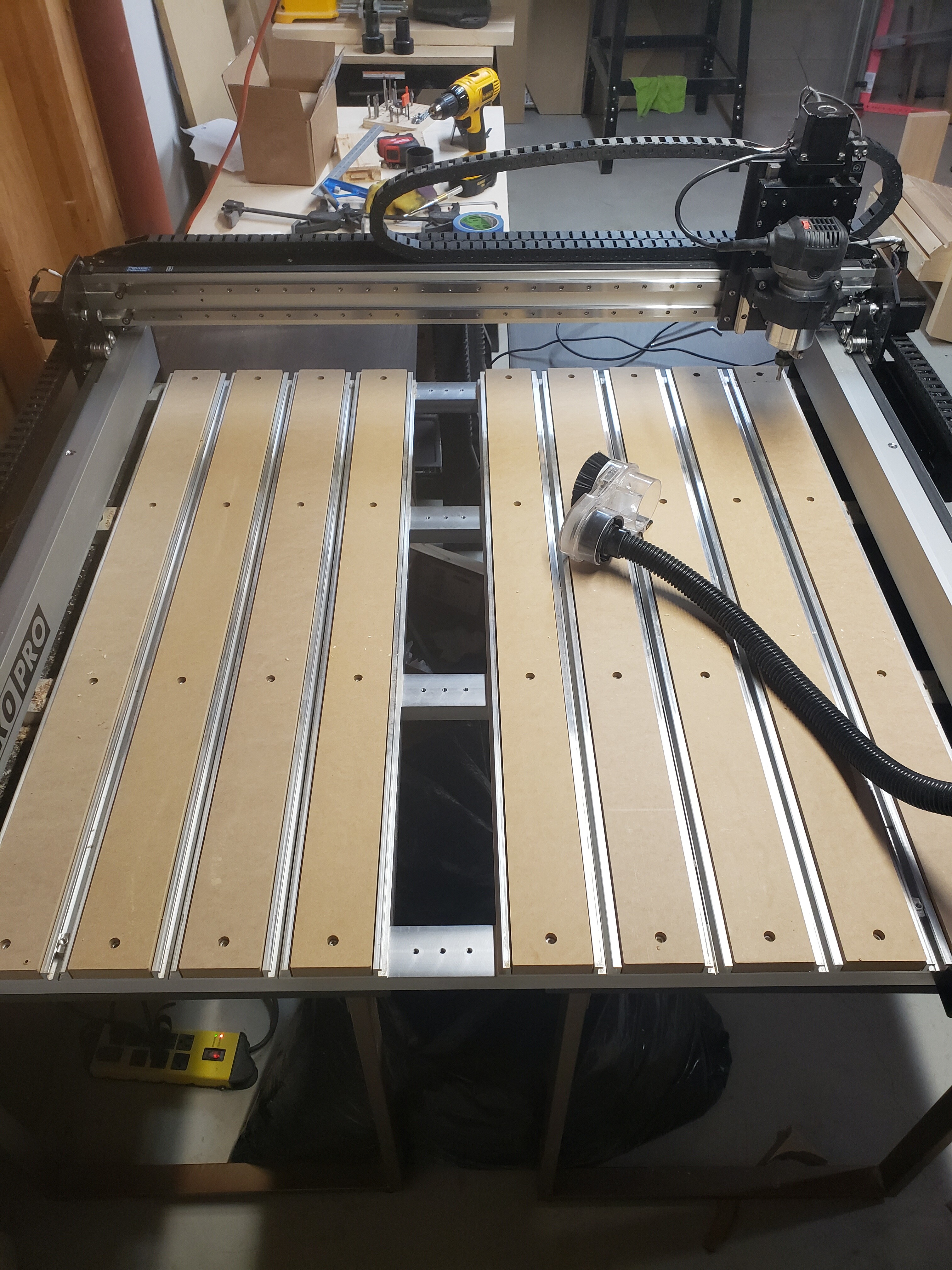
So check this out. I reoriented my machine. It sits on 2 tables so it was actually a perfect setup for what I am trying to accomplish. I have a simple vise that I worked up that should work for now, though I want a faster anf more convenient setup in the future. I calculated that I would be able to squeeze in a piece about 10.5 inches wide and 3.75" thick in the given area with a length up to 38" unless I raise the machine up more. Should be fine for now!
You could always use your machine to mill a slot the size you would like out of one I’d the aluminum slats and the assotiates spoil board piece. Then you still have the structural stability it provides but have a vertical slot to use for vertical milling. You could even cut the spoil board slot larger and make two inserts one with a hole the exact size of the hole you cut in the spoil board so that when you aren’t vertical milling there would be no hole in your surface and one with attachments to allow clamping easily.
That is an interesting idea. I do like the idea of having that extra stability. But I am torn on cutting thru the aluminum though. I guess I can always order a replacement slat. I am not one for coming up.with creative and functional plans yet though…I would struggle with coming up with a clamp design like you mentioned… Its hard for me to wrap my head around the technical/engineering portion of things. I need to get better at that!
Yeah I usually just wing it. I will start with an idea and figure out the specifics as I go. If I plan it all out before hand it never seems to work correctly.
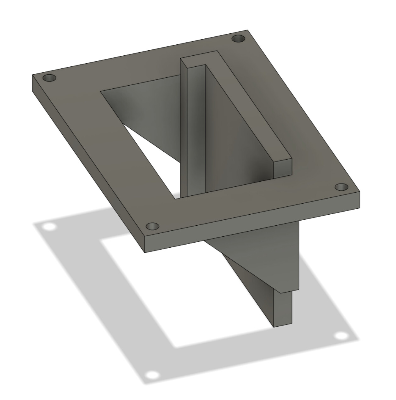
I’ve also been thinking about how one could adapt the t-slot table for vertical work holding to do dovetail, box joint, etc… and was thinking along these lines as well by removing one of the aluminum extrusions or creating a slot in one of them. In either case you would want to make sure that you clamping is perpendicular/parallel with the x/y/z movement of the machine. In this case I’d probably start with a surfaced wasteboard which is a great reference point in the x and y plane and using the t-track system will likely be good enough to stay square with the machines movements. So if you are going to remove 1 of the aluminum extrusions maybe a clamping jig that sits on top of the table and gets bolted into the t-track system would be a good starting point. Something like this could maybe work with some clamps to hold the workpiece in place (2 on top and 1 underneath) pushed back against that back edge so it’s square with the router bit/machine.
I would confirm that. Completely anecdotal, but iirc I’ve seen statements that individual parts like that aren’t stocked except for warranty/repair claims (which I don’t think this falls under haha).
Carbide is a great company so they may work something out with you on the down low that’s not the official policy, but just thought I’d mention it!