Hi - My issues trying to bring up my aging S3 continue. I finally fixed my motor juttering issues by replacing a wire and a motor connector of all things (check those carefully first). Now that the toolhead is happily moving about, I can’t get the VFD to spin up!
I sent a request to support, but thought I’d also document the issue here for others. Here’s the message I sent to support:
Hi guys -
I’m having some trouble with my VFD, hoping you can help. I desperately need this machine running ASAP.
Quick history: I bought the VFD last year, used it for a bit, then moved houses. I’m just now getting back up and running after several months. Anyway, that’s just to say that I know the VFD worked at one time and I don’t have many hours on it.
What I’ve done so far:
Verified that the control box can move the spindle by pressing the “jog” button on the face of the VFD controller. It briefly spins.
Checked the voltages of the S3 Grbl control board: Gnd-Red → 24V Gnd-White → variable voltage (using multimeter) of 0 at M5 command issued to a little over 2V at M3S10000 command issued and just a hair under 5V at M3S24000 command issued. I haven’t scoped the PWM pulses to see what they look like.
Verified that the enable button is on/lit in red.
Verified and repeated “set up new machine” and made sure that the VFD spindle was selected. I also looked in the settings list and see that “spindle type=1”.
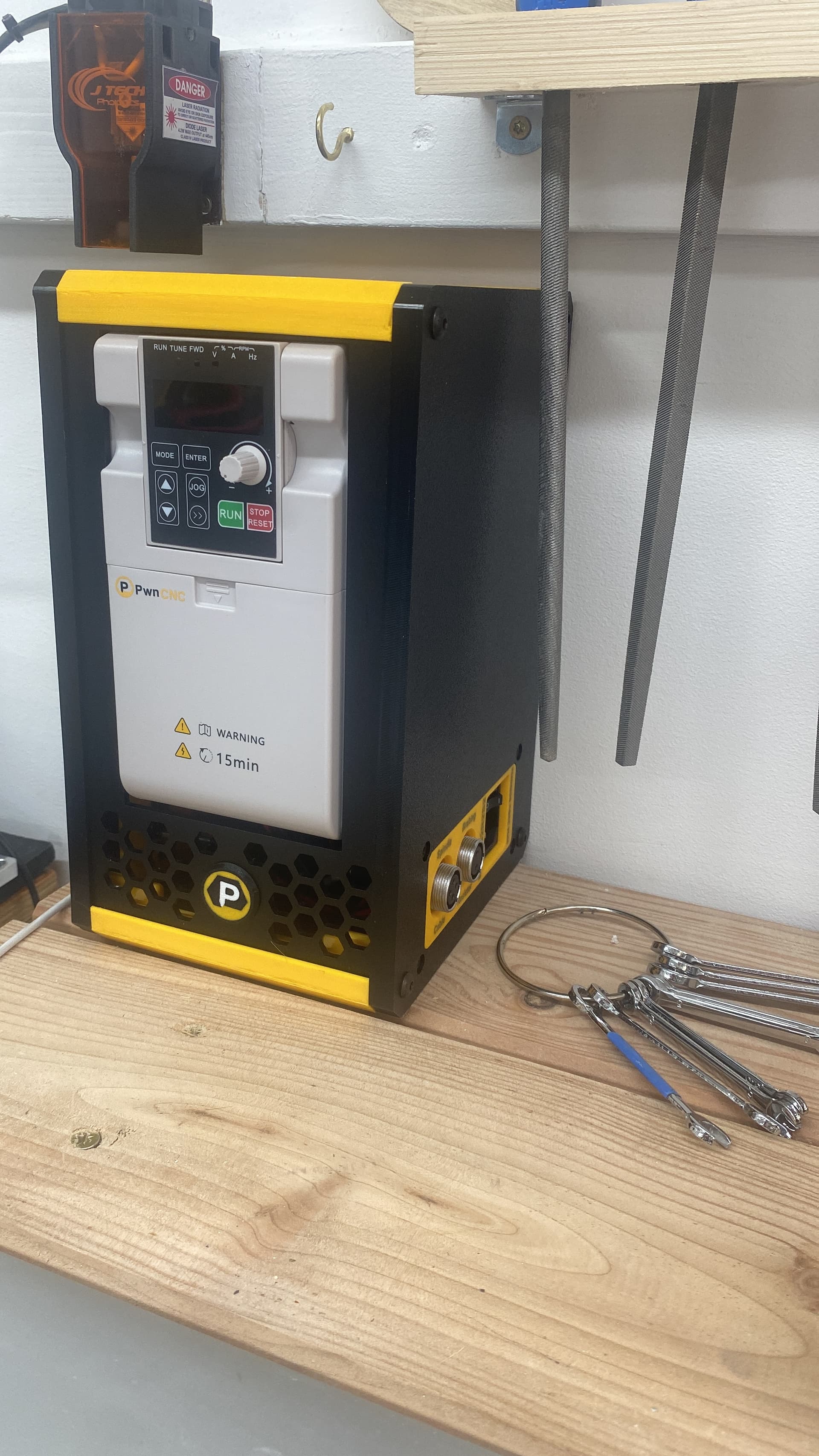
Attached is a pic of the front of the VFD box. That 0.0 is flashing. Is it in the wrong mode or something? what other tests should I do?
Please help!
thanks
Since then, I have checked the resistance between the AC input ground and the controller cable connector ground, resulting in 200Kohm. Between case and the AC input ground is 0.2ohm. I’m not sure if the AC ground is decoupled from the DC ground, so I can’t evaluate that number.
This may be dumb but… if the 0.0 is flashing that means that the VFD is awaiting automatic signals to the controller. When there is a single 0 the VFD is awaiting instructions in manual mode. If you turn the control for speed and it is in manual mode, the spindle will spin up. I have the identical VFD supplied by PwnCNC and it has an outer case and a switch to change from manual to automatic mode. Just a thought.
hey, ain’t nothing dumb to these ears… I’m new to VFDs, so I appreciate any ideas.
I don’t suppose you could do me the favor of testing impedance from AC-ground to signal ground on the controller-cable connector? I get 200K ohms and I’ve read some posts which seem to indicate that’s a problem. would you mind? or, anyone w/ the VFD? thanks all!
oh, and I don’t see such a switch on my unit. I understand that Carbide created some kind of interposer circuit internal to the box which is supposed to take the guesswork out of operation, so its very possible they did away with any kind of manual mode. That said, pressing “jog” does make the spindle move a little.
I am sorry Chris, I would not know how. My S3 has been mine since October 2020 and I put off getting a spindle/VFD because I do not have sufficient knowledge or understanding of electronics. I purchased my Spindle/VFD from PwnCNC because it was completely configured. I only had to plug the power cord into a socket outlet and the control cable into the PWM port. Everything worked as intended in auto and manual mode.
The link (just watch the first two minutes and 10 seconds) of PwnCNC spindle/VFD for Shapeoko 4 and Pro installation the outer casing the facilities provided.
thank you! the image is helpful, as I start to educate myself on the various options available. thanks also for the link, I’ll watch soon. I’ve seen several references to PwnCNC in the forums! I wonder what Pwn means…
In the form “PWN3D!”, it was taken to mean ‘owned’ if another person had beaten you at some sport/game. It may still have that connotation so I cannot explain why PwnCNC is so named. Their strap line is something akin to “don’t just own your CNC machine but dominate it!” I guess they are saying we can help you to really own your machine.
wow, they adopted what amounts to an inside joke of an already nerdy phrase. they have certainly OWN3D nerd-dom! But I’m a nerd so I can appreciate that, plus I love the apparent passion for cnc, so kudos to them!
They forgot to remove the ground pour on the DC side of the PCB where the screws hold the PCB to the chassis. Some units will have low resistance, some units will have higher resistance and some will be open. It depends on how tightly they mounted the PCB and if the screw is touching the side wall.
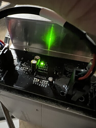
You can try opening up the side panel of the VFD and check for a green LED light on the PCB when it is connected to your shapeoko with the power on. You have already verified that the Shapeoko is providing the 24V so if you do not see the green light then your PCB likely has a fried transistor(Q3).
To fix your problem you can contact C3D to see about them sending you a new PCB or replace Q3 with a 0 ohm resistor as mentioned in a previous post of mine found here.
A) what additional functionality comes with the Q3 being replaced with the same transistor component vs the zero ohm resistor rework. Said another way, is there any disadvantage of the 0-ohm R rework?
B) if I were to replace Q3 with the same component (rather than the zero-ohm), how do I fix the grounding issue which fried it in the first place?
Am I correct in understanding that you don’t want the DC/logic side of the board ground to be coupled to chassis ground? So, if I were to be able to isolate the board from the standoffs and case with some nylon washers or tape or the like, would that fix the underlying issue, such that a Q3 replacement would be safe from future frying?
Of course, I’d rather have a new board and not have to do any of this (and it seems like C3D support might do that), but in case they don’t or there are long delays, (and for people searching for help with this problem in the future) I’m wondering if someone might be kind enough to comment on the above.
Well, here’s a fun thing! I did the 0-ohm resistor rework as mentioned by @Gibs (thank you) and it’s still not working! that said, C3D sent me a new circuit-board, which I received today. I’ll update this thread with progress once I’ve installed it and running it. thanks everyone for all of your help.
well, as I mentioned, the zero-ohm-resistor rework did not work for me on V 1.1 of the Spinderella board, so there’s that.
However, C3D was good enough to send me V 1.2 of Spinderella, which I installed to the VFD box per the instructions and that did work. So, not sure why the fix to the older ver 1.1 didn’t work, but I’m finally back up and running w/ a new ver 1.2 board. so, big yay there.
on the aside, getting me running again took a big chunk of time, during which I happened to have a C3D router spindle delivered, so I started using that. It did the job okay, but Criminey that thing is loud! Had forgotten how darned loud it is. Also, I’d gotten used to not having to turn it on and off manually, so there were a couple of “oh shit” moments there, to pop over and switch it on before the bit hit material. Guess I’m just saying to anyone on the fence: once you go to VFD, the convenience and silence make it tough to go back.