Well that is an excellent question…considering my values were close enough (see RPM table I posted earlier) that I did not bother to look further into calibrating the commanded RPMs.
Your question gave me an opportunity to read the manual again, and I hoped this would be done using the PD072 and PD073 parameters (which theoretically provide a way to adjust the frequencies corresponding to 0V and 5V on the PWM). But the documentation is unclear (to me), so I got lazy and tried an easier way: adjusting the PWM average voltage that your board generates.
If I plot your actual RPM values (from a separate post) versus the commanded 10.000 / 12.000 / 24.000 RPMs, I get the orange line on the chart below (the value at 0 is just linear extrapolation). The green line is what we would want ideally (1 to 1 mapping)
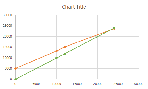
So we need to decrease the slope of that orange line. GRBL uses $31 for min RPM and $30 for max RPM, and even though I did not check GRBL code I’m pretty sure that the PWM generation logic is something like PWM_voltage = (requested RPM - min RPM) / (max RPM - min RPM) * 5V
(the controller actually controls the PWM duty cycle, but that’s a detail)
So I figured, let’s try to change that slope by artificially increasing $31 / min RPM in GRBL.
I tested on my machine, and sure enough, for a given RPM command (say M3S12000), if I set $31 to something greater than zero, the actual value on the tachometer decreases. And the maxRPM should not move, since $30=24000 means that the end of the curve is still 5V=24000.
I’m too lazy to do the math to figure out exactly how much you should put in $31, but I suggest to figure it out experimentally:
- set $31 to e.g. 200, instead of 0
- do M3S12000 and measure. The actual RPM should now be lower than the 15120 you saw initially. If not, lower $31 a bit and retry.
- increase or decrease $31 until that 12.000 RPM value is spot on.
- finally check whether M3S24000 still gives you close enough to 24000 (23712 on your spindle)
Let me know if this hack works, maybe others will chime in to explain how it is properly done at the VFD side 