Interesting. A few minutes of warm up per shapeoko session might not be such a big deal if there is a real value for bearing life. Does anyone here do this?
it also brings things up to tolerance - in this instance you may notice the effects.
it’s common for larger cnc machines to go through a warm up program that essentially bring everything to operating temperatures - before any actual subtractive mfg. this way bearings and ways warm up and can effectively tighten up a bit. then you have that little bit more consistency. on stock parts i’d be surprised if you could distinguish, but on that spindle you may see some signs.
3 Likes
This makes sense, I’ll keep this in mind if/when I do precision stuff.
I’d had my Dewalt that I’d turned off decide to turn itself on as I was preparing to change bits. I just about wet my pants. I now unplug it entirely
2 Likes
Just pointing out, this is something that not only Shopbot recommends but also Haas, Hellman CNC, and CNCCookbook. Although you’ll always find people who say they’ve never done it and it’s been fine for them.
1 Like
Interesting links! Sounds like a best practice, though it is likely that it would not make much of a difference for my amateur use of the spindle. It does not hurt to be a little careful, so I’ll try to at least let it warm up a few minutes at low speed as part of my routine. Thanks for the tip!
I am not sure where to put this, but I have an xxl with the beaver hdz and the 2.2kw water cooled spindle with the HY VFD. It is wired like this says. I have went through all these settings over and over. I have been using aspire to get my gcode, but everytime I use it, my spindle goes to 24000 no matter what rpm I put into the program. Also, when I simply click spindle on in cm, it goes to 24000. Does anyone have a clue what I might doing wrong.
does this also happen when you type M3S10000 from the g-code shell ? (M5 to stop)
I don’t use CM anymore so I don’t know what RPM it commands when you click spindle on.
can you check in GRBL that $30=24000 but also that $31=0? (this is min RPM)
I think you should unplug the PWM wire from the shapeoko, use the spindle on command (or the M3 command) and check with a voltmeter what you see there: if it is 5V (or close) then the 24000 RPM you get is expected and the problem lies somewhere in CM/GRBL, if it is lower (say 2V for 10.000RPM commanded) then the pb lies at the VFD side in the parameters, and we can go from there
@Julien the indicated speed on my VFD averages higher (except top end which is lower) then my requested speed i.e. s12000 reads 15120, laser 15125; s10000 reads 13296, laser 13289; s24000 reads 23712, laser 23700.
How would I accomplish the tuning you mentioned?
Thanks.
1 Like
Well that is an excellent question…considering my values were close enough (see RPM table I posted earlier) that I did not bother to look further into calibrating the commanded RPMs.
Your question gave me an opportunity to read the manual again, and I hoped this would be done using the PD072 and PD073 parameters (which theoretically provide a way to adjust the frequencies corresponding to 0V and 5V on the PWM). But the documentation is unclear (to me), so I got lazy and tried an easier way: adjusting the PWM average voltage that your board generates.
If I plot your actual RPM values (from a separate post) versus the commanded 10.000 / 12.000 / 24.000 RPMs, I get the orange line on the chart below (the value at 0 is just linear extrapolation). The green line is what we would want ideally (1 to 1 mapping)
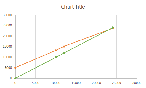
So we need to decrease the slope of that orange line. GRBL uses $31 for min RPM and $30 for max RPM, and even though I did not check GRBL code I’m pretty sure that the PWM generation logic is something like PWM_voltage = (requested RPM - min RPM) / (max RPM - min RPM) * 5V
(the controller actually controls the PWM duty cycle, but that’s a detail)
So I figured, let’s try to change that slope by artificially increasing $31 / min RPM in GRBL.
I tested on my machine, and sure enough, for a given RPM command (say M3S12000), if I set $31 to something greater than zero, the actual value on the tachometer decreases. And the maxRPM should not move, since $30=24000 means that the end of the curve is still 5V=24000.
I’m too lazy to do the math to figure out exactly how much you should put in $31, but I suggest to figure it out experimentally:
- set $31 to e.g. 200, instead of 0
- do M3S12000 and measure. The actual RPM should now be lower than the 15120 you saw initially. If not, lower $31 a bit and retry.
- increase or decrease $31 until that 12.000 RPM value is spot on.
- finally check whether M3S24000 still gives you close enough to 24000 (23712 on your spindle)
Let me know if this hack works, maybe others will chime in to explain how it is properly done at the VFD side 
3 Likes
I’ve set my xPro to $31=3000 and $30=24000. Also changing to 10v signal gives me much better result with much smaller rpm deviation. The rpm’s on a vfd are almost spot on to the actual spindle speed (measured with laser tachometer).
2 Likes
Yep, that did it. Switched to 10v and $31=3500, pretty much spot on now.
2 Likes
I didn’t see where PD176 gets set, how would it be set for users in the US (i.e. for 60 Hz).
PD176=1 means “60 Hz” (from the manual, obviously I never had a chance to test it)
EDIT: I wanted to go and update the large post where I dumped all values, to mention this, but for some reason I can’t edit anymore.
Maybe @WillAdams can fix that.
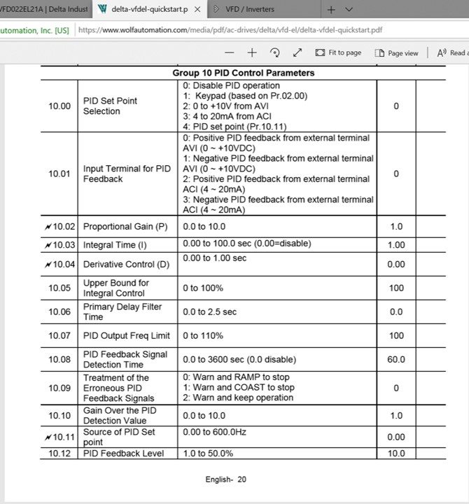
IMO you were wise to leave PID off. The differentiators in PIDs can cause instability if the system’s characteristics are modeled improperly or change (i.e. loading changes, etc.) You may have witnessed that with elevators sometimes “hunting” (oscillating) when trying get to the commanded location. If everything works properly, the integrator part of the PID enables the elevator to get there accurately and the differentiator part gets it there fast. As shown below, the Delta VFDs also default to PID off. Hopefully this post isn’t too OT!
1 Like
Did anyone ever check the live current value on their Huanyang VFD ? I am finally getting to the item in my todolist called “measure K factor of various materials”, but when I set the display to show Amps (“A<xxxx.x>” on the LCD), the displayed current value does not seem to ever change much, whether I’m cutting or not. With my spindle running in the air at 18.000 RPM it shows 1.5A, and when I’m pocketing in oak at 0.125" DOC and 0.125" WOC, first at 70ipm then 200% feedrate override, it still reads exactly 1.5A…Ideas ? I checked the user manual, but was not enlightened.
I ran @gmack’s spreadsheet, and I should be seeing an increase of at least 1 amp when cutting

1 Like
From “@Hooby’s Wood Hardness” sheet in the workbook the Janka hardness of yellow birch is 1260, red oak is 1290, Santos mahogany is 2400, and yellow poplar is 540. As shown in the “Measured K Factors” sheet, my K Factor measurement estimates were 9.45, 17.5, and 22.68 cu-in/min/HP for Baltic birch, Santos mahogany, and yellow poplar. GWizard uses 18.8 cu-in/min/HP for plywood. A 0.125" DOC would be cutting through 2 layers of glue in Baltic birch and likely no glue in oak plywood. So, your actual K Factor might be twice as high as that shown which reduce cutting power and force by a factor of 2.
What’s your spindle current when not cutting? Is it warmed up?
2 Likes
Yes I did a good 5 min warmup. The current when not cutting is…identical, which is why I question the readout. This is solid oak.
Sorry, I should read everything before responding! Do you have a current probe/meter? If so, you can measure the current into the VFD and estimate the spindle’s cutting power (and current) increase from that as a sanity check.
Right, I don’t have a current meter but I have a basic powermeter, so I will plug my VFD on that and check the difference between cutting and not cutting.