VFD Parameters (Huanyang model)

It seems to me that only PD144 would be impacted, but someone from the US who installed this VFD could confirm.

mine came with a fancy printed instruction book;
pd144 says

Set Range: 0 - 9999 Unit 1r/min factory setting: 1440

This is set according to the actual revolution of the motor The displayed value is the same as this set value. It can be used as a monitoring parameter, which is convenient to the user. This set value corresponds to the revolution at 50 Hz

I can’t quite remember how mine was mapped, but I kept having grounding issues. GRBL would stop for no reason half way through a toolpath. I earthed everything, but was still having issues. Then I opened that connecter at the top of my spindle. Ground pin was not connected to anything!
I connected it to the spindle housing. Not had a problem since.
So with a Chinese spindle it’s probably good practice to check the wiring!

2 Likes

That is disturbingly common on the Chinese spindles, I would check the earth before even thinking about powering them up.

1 Like

Apart from that, it has been excellent. Inexpensive, but good! I would never go back to a noisy brushed trim router!

2 Likes

I too have opted for a spindle, helped over the line by G-Penny/AliExpress doing a -17% Black Friday offer for spindle and VFD combined.

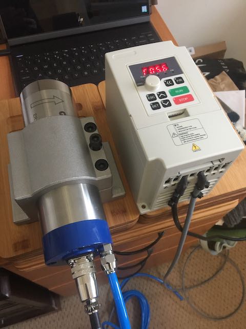
Having got over my ‘more power = better’ cravings, I opted for the 800W/220V/65mm/ER11 model with the ‘mini’ 1.5KW VFD.

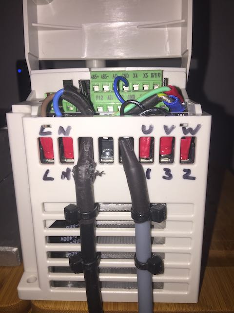
Having read @Julien’s notes above, I was interested in what differences the ‘mini’ version of the VFD would bring. The first thing to note is that I correctly (double-checked) wired connector pin 1 to ‘U’ on the VFD, pin 2 to V, pin 3 to W and pin 4 to Earth + cable braid, and got reverse rotation. I swapped 2 and 3 and now see correct rotation. I want to read up on this just to be 100% sure I haven’t got phases competing with each other for having done this, but it would appear not.

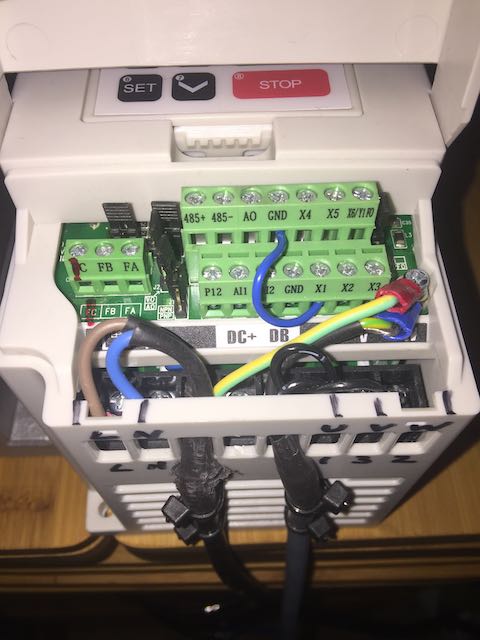
The small VFD didn’t need the jumper VI setting as the out-of-the-box settings (soft and jumper) were correct. Just needed to install the ‘Forward X1 to GND’ jumper, as also shown above.

Worked through all of the PDxxx settings described above (in the mini these are Fxxx settings), and read the manual front to back, then back to front to be sure I agreed with them all. Left F001 and F002 as Keyboard and Potentiometer control, then successfully started up the spindle at 5hz for 1 min just to confirm a) direction of spin, and b) proper function - keeping in mind that I haven’t yet hooked up the coolant.

Next step is mounting the HDZ 65mm clamp (from Carbide, not the G-Penny clamp) on my HDZ 3XL, hooking up the coolant and water flow indicators, water temperature display and then go through the ‘start it slowly and let the bearing grease sort itself out’ routine.

2 Likes

thanks for reporting, it will be quite useful since people buying now will likely get that new VFD series.

I created a small “5min warmup” macro that executes a series of M3S[xxx] following by G4P30.0, with xxx from 500 to 24000 in steps of ~1000, giving it 30 seconds per step. I found it to be a good compromise (long enough that it really is a warm-up, and short enough that I won’t be tempted to skip it when I am in a hurry). I run it a single time at the beginning of each session in the shop. It may or may not be strictly required, but it can’t hurt my bearing’s life and precision.

2 Likes

You did the right thing, one definining characteristic of a three phase motor is that if you invert any two connections it will spin the other way, this applies to BLDC motors too.

1 Like

I don’t have a tachometer with which to measure spindle speed vs GRBL request. Any real-world tricks that anyone has found to be successful? I tried the Gates app, but the sound is too ‘noisy’ for it to focus on the fundamental frequency.

I wouldn’t worry much about this, if you have set it up as per the instructions and what’s printed on the side of the spindle then the VFD controls the target speed and the spindle should be somewhere between 97% and 100% of that depending upon how heavily loaded it is.

The key parts of that are to tell the VFD what the normal frequency of the spindle is (probably 50Hz) and then the max frequency (probably 400Hz for 24,000RPM) and get the voltage right.

The VFD sets the frequency the magnetic field spins round at and the rotor mostly keeps up with that. There is a small ‘slip angle’ when the motor does work, this is how the motor draws more current to deliver more torque.

So, the RPM displayed by the VFD should pretty much be the spindle speed.

3 Likes

All good with the spindle, except one thing. The speed (as shown on the VFD) is 780 rpm when M3S1000 is given, but more significantly the ceiling rpm is 3,000. I’ve probed the CM board PWM output which does reach 5v (or near enough) for 24,000 rpm M3S24000. The spindle speed increases roughly linearly vs M3Sxxx setting up to 3,000 but then no further increase happens. Checked and double checked the various VFD settings, $30 is 24000 and $31 is 0 on the CM board. Any thoughts?

What is your PD144 set to on the VFD?
(that’s max rpm)

PD144 is set to 3000 as-per the “corresponding to speed at 50hz” description and @Julien’s reiteration

What do you have for PD070?

The manual for my model says;
0 -> 0-10V
1 - > 0-5V

And the others are non-voltage settings. I suggest checking your manual for your model.

Also double-check the equivalent of params PD072 through 76 for your VFD maybe, since those parameters configure the mapping/curve between the input voltage and the output RPM (on the old Huanyang series that is, I’m not sure about new models)

PD070 is set to 1 (0-5v) and input applied to AI1 port, set to control rpm via AI1.

1 Like

The frequency curve settings all appear the same, and have the same descriptions for each in the manual. Where my thinking has got to is that a rpm ceiling of 3,000 is 1/8th of max, exactly as 50 is 1/8th of 400. So my thinking is the Mini VFD needs one setting - I could imagine this being Reference Frequency - being 50, dealing with the 1/8th. Will try this on the machine having only got it as a theory for now

Something odd is happening. Laser RPM meter arrived, and on manual control (keyboard/Potentiometer) and F143 = 2 poles, F144 set to 240 then the RPM is correct to potentiometer 0-400 giving measured rpm to 24,000. Reference and Max Frequency set to 400. So under manual control, it appears to be OK.
Switch back to External Terminal and AI1 with these same settings (most notable F144=240) and M3S1000 results in 6,000 rpm by M3S5000 the spindle has reached measured 24,000. AI1 mode is set to F070 = 1 (0-5v) and F072 = 400 (high-end analog freq). All very perplexing…
Repeated posts and references say that F144 should be 3,000 for 50hz mains, 2 pole and 400hz spindle, yet that doesn’t work even under manual control, only F144 = 240 gave correct RPMs

Well, for a freezing, foggy day here in the UK, I’ve got the thing working… It appears that the VFD I have is not the same setup as Huanyang. This is Jiangsu Decoder Electric model H100, 1.5KW 220V 50Hz ordered with the G-Penny 800w water cooled 24000 rpm spindle as a bundle.

Major settings that resulted in it working now (either that or the rapidity escalating expletives offered as ‘encouragement’ when the expected settings didn’t work!!):

F001 set 0 External Terminal control
F002 set 1 Analogue Qty frequency setting
F004 set 400 Reference Frequency
F012 set 0 Drive Control VF
F044 set 02 X1 Function = FOR and wire this terminal to GND
F070 set 0 0~10v Input channel selection for Analogue qty
F072 set 97 High-end Analogue Qty (not 400 that Huanyang needs)
F073 set 0.1 Low-end Analogue Qty
F080 set 0 Multi-Segment speed ‘Normal Operation’
F141 set 220 Rated Voltage of motor
F142 set 4 Rated Current of motor
F143 set 2 Number of motor Poles (appears to be 2 unless you know for certain it is 4)
F144 set 24000 Motor rotating speed (not 3000 that Huanyang needs). To set this value you have to scroll the numbers up beyond 9999 then the display switches into ‘thousands mode’
F159 set 100 Target PID value
F160 set 0 PID channel setting to follow F159

ShapeOKO 3XL Carbide Motion Controller is set $30 = 24000 and $31 = 0. Probed the PWM signal and it is correctly outputting 0.1-5v divided into 255 steps according to the GRBL speed request 0-24000 rpm.

Spindle speeds measured with a laser RPM meter: above 1000rpm are within 2% or so. Below this the Constant Torque settings in the VFD start interacting with the actual RPMs.

2 Likes

Happy New Year!

I bought a 110v 1.5kw vfd and spindle and can’t get it work, I read all the comments above and still can’t get mine working. It wont spin past 10-12k rpms. I’m not sure if settings are different versus the 220V settings. Any suggestions?

Thanks!

Do you know if you have the Huanyang model, or the Jiangsu Decoder Electric model? Or something other than these two common models? The setup for these differ in a few key areas such that following the wrong tips will not likely make it work. If the label on the unit (the VFD) doesn’t say, the instruction booklet likely will.

1 Like