Hey all, I setup my new Shapeoko 5 Pro 4x4. But I’m having trouble figuring out what height to set my VFD Spindle. I contacted Carbide3D Support and they said set it to whatever high you need just as long as the “bitsetter without running out of travel room”.
So I’m left, as someone new to CNC, wondering what I should set the collet nut to the top of the waste board distance to. I don’t know what I’m going to be doing, I want to try a little of everything and learn in general. Does anyone have any guidance?
Thanks, but I already watched this and Winston said “put the spindle at the same height as your router was”, but I’ve never had a router, this is my first machine and I bought it with the spindle.
OK, so do I lower the Z all the way to the bottom? Also, do I position it right over the BitSetter and press the BitSetter button down all the way with the spindle and bit? Or did you mean the below the housing of the sensory where it connects to the base frame of the machine?
I had a hard time even getting the colett nut screwed on with my new surfacing bit. But I don’t even know how far out the bit needs to hang out from the colett nut. When I put the surfacing bit in I can push it all the way into the colett, is that right?
I’m asking a lot of questions, but I’m just trying to understand.
If you want a starting point, on my 4 Pro the bottom of the nut of the router sits about 125mm / 5" from the TOP of the spindle bracket. I measured the top because I don’t know if the 5 Pro has a different bracket but even if it does then the distance from the top to the nut will still be the same on both machines.
I would make a correction that what you care about is “Can my endmill reach the table”, not "can my endmill reach the BitSetter. Because on the Shapeoko 5, the BitSetter is above the table, not flush with it like on the Shapeoko 4 or Pro.
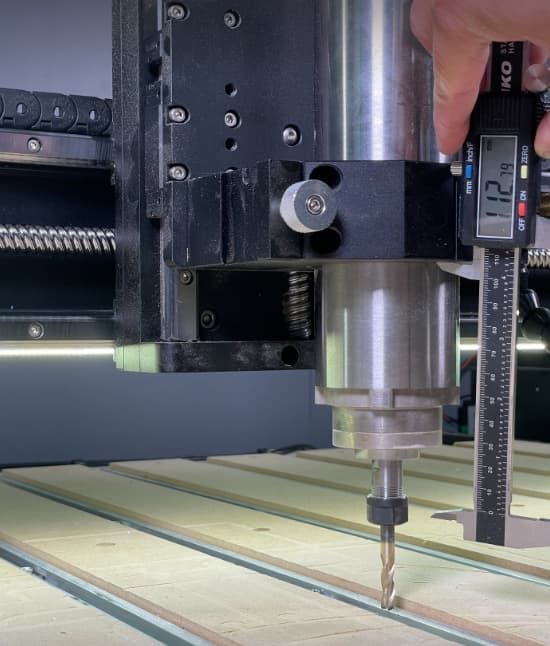
For reference, here’s how we have the VFD setup here. The collet is hanging about 110mm below the bottom of the Z-axis plate, and we still have plenty of travel to go down and reach the table, even if our endmill wasn’t this long. I think 100mm below the plate would be fine.
Also of note is that our spindle mount is in a lower position (this is why I reference the bottom of the Z plate, not the mount). This is usually reserved for using a (shorter) Router with the machine, but since we need to be able to switch back and forth, we keep it here. Using a VFD with the “Deep Sweep” boot, you’ll likely want to use the higher spindle mount position so that you have a larger length along the spindle to clamp/adjust your dust boot height.
@wmoy Thank you so much! I know it can vary, but I just needed that stating point as a noob.
Now all I need to figure out why when I set Carbide Motion to use the spindle it claims some position needs to be set, watching your video it shows x0 y0, mine does too, but it still complains.
Also how much of the shaft of any given 1/4 and 1/8 bit needs to stick out.
What is the context for, and exact language of the complaint?
Tools should be inserted so that they are fully inserted into the collet — some folks will go deeper, some tools have min/max insertion marks which should be abided by.
The BitSetter is pretty much automatic:
configure per the instructions
allow the machine to measure the tool
only change the tool when prompted, or when using the interface to request a new tool load
OK, I have 3 different good/high quality bit brands, none of them have min/max marks sadly.
The error is: “X travel must be between 50.0000 3000.0000”. I see X and Y boxes and both show zero. I wasn’t sure if I need to mess with that or not, Winston’s video shows him selecting the VFD Spindle, then clicking OK.
To follow up on what @WillAdams said. The bit should be inserted so it is at least as high as the top of the collet. This gives you the best grasp of the bit. You can insert the bit higher in the collet but never all the way up. When collets tighten it moves the bit and collet up an inclined plane to tighten it. Also the top of the spindle shaft may be rough and cause a bit to be out of round. So for a Makita collet it is about an inch long. So you could mark the bit with a magic marker at about 1.25" and insert into the collet to that mark. Now some bits like the #102 1/8" bit has only about a 1/2" cutting depth so it would be higher from the spoilboard than a #201 with both inserted 1-1.25" in the collet.
Depending on what bits you use most often you just have to compromise to get the longest bits up high enough from the spoilboard and the shortest bits close enough to reach it if you are cutting through the material.
Once you get the spindle located you can move it but you would need to tram the router each time you move its position. So pick a spot that the small bits will reach and if necessary move it up.
I fixed that error, I realized under the machine tab I didn’t select my machine version and load the presets.
When I try to run the M3S10000 command nothing happens. The power is on, I see numbers on the display, and the data cable is connected to the controller.
One thing I noticed was when I was loosing the two bolts on the spindle mount it was really hard (I didn’t crank them down that much) and I could only go in small increments and smoke (I’m not kidding) would come out with each increment. Then it loosed up and acted like a normal bolt. It makes a loud noise when it gets tight, like squeaky metal sound.
One other question, when the X and Y are moving at the same time, is it normal to hear a louder more labored sound from the steppers? I can move each individually and it’s a normal sound, but when it’s doing it’s homing cycle it’s much louder for instance.
When tightening the spindle mount, it’s like when changing the tire on a car — alternate and switch back and forth between the fasteners so as to ensure that you get everything evenly tightened.
Yes, the machine makes a different noise due to resonance at some speeds when moving both X- and Y-axes — it’s normal — the big question is how things turn out when you cut.
So I was messing with the machine more tonight getting things down and finding out I ordered the BitZero for the Shapeoko 3/4 and not the 5 (gee yay). But I noticed that when X and Y are moving together it gets alot louder, especially when Y is at the midway point. The sound is louder on the right side of the machine. It’s not a grinding sound or anything, but the labored stepper sound is really loud compared to normal individual movements. The machine is square the last time I checked, same distance from the corners at the same points of measure.