VFD & Spindle not working Shapeoko 5 PRO NEW

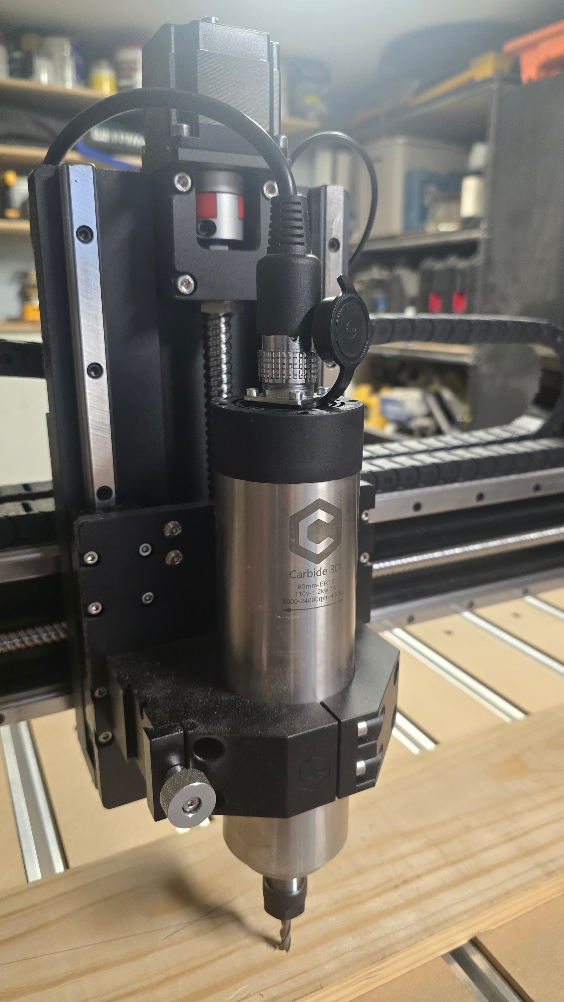
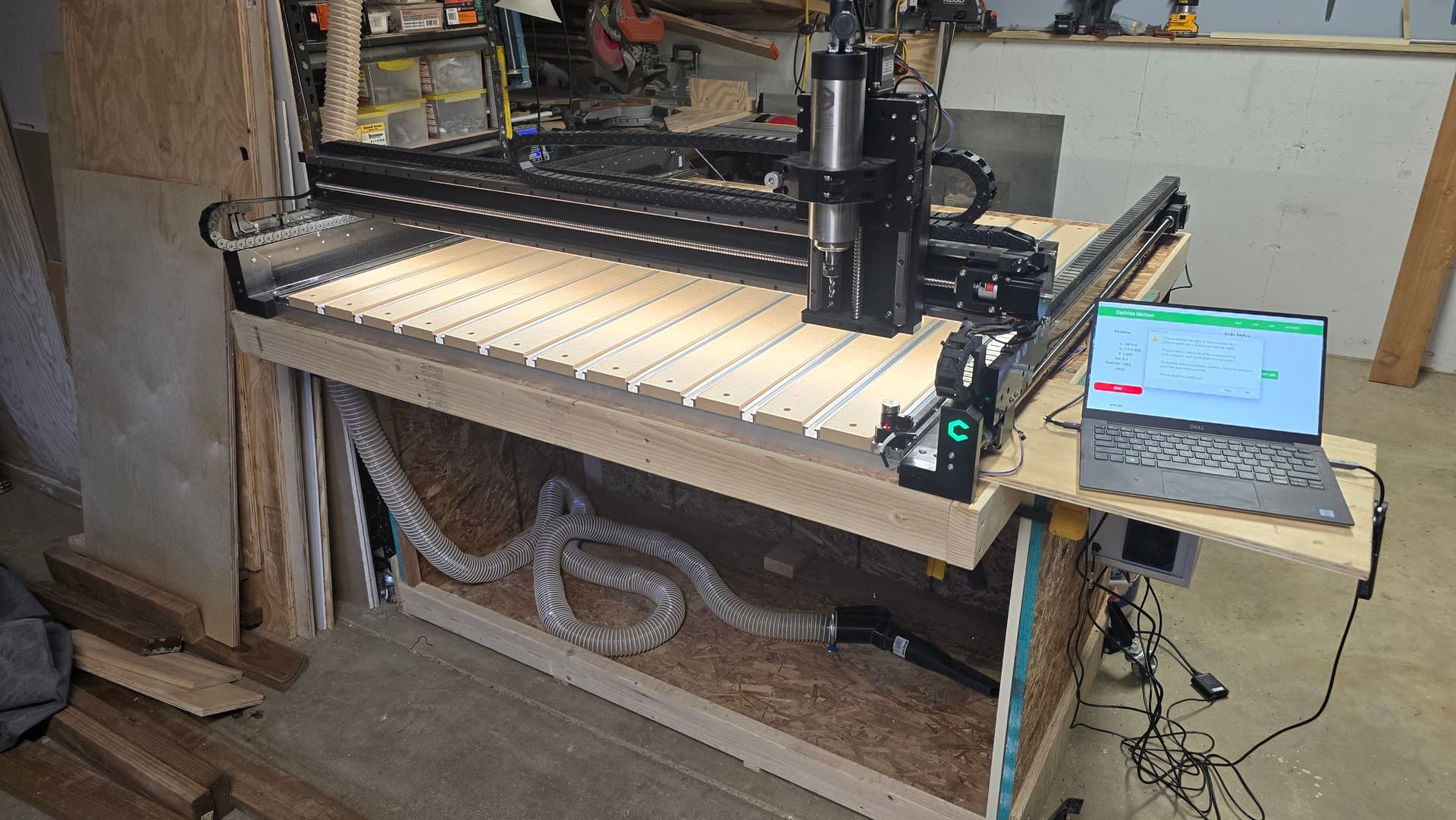
I purchased the Shapeoko 5 PRO on April 16, received it fast, and assembled it. I also built a folding table for it. At the time, the Spindle hadn’t arrived yet - it arrived two weeks later. Since then, I haven`t had any time to play with the machine, and today I finally assembled the VFD Spindle and tried to make my first cut.


Issues :
Carbide motion frequently " not responding" version 649

I made a simple circle file for wood cutting in Carbide Create ( free version) with a depth of 3mm and bit #201 1/4 shank. When I try to start a job says: The project will hit the right side of the machine. The program zero is 309.mm, or if I change the position of the wood piece in the program when creating the file, it changes these values, but still warns will hit some of the sides

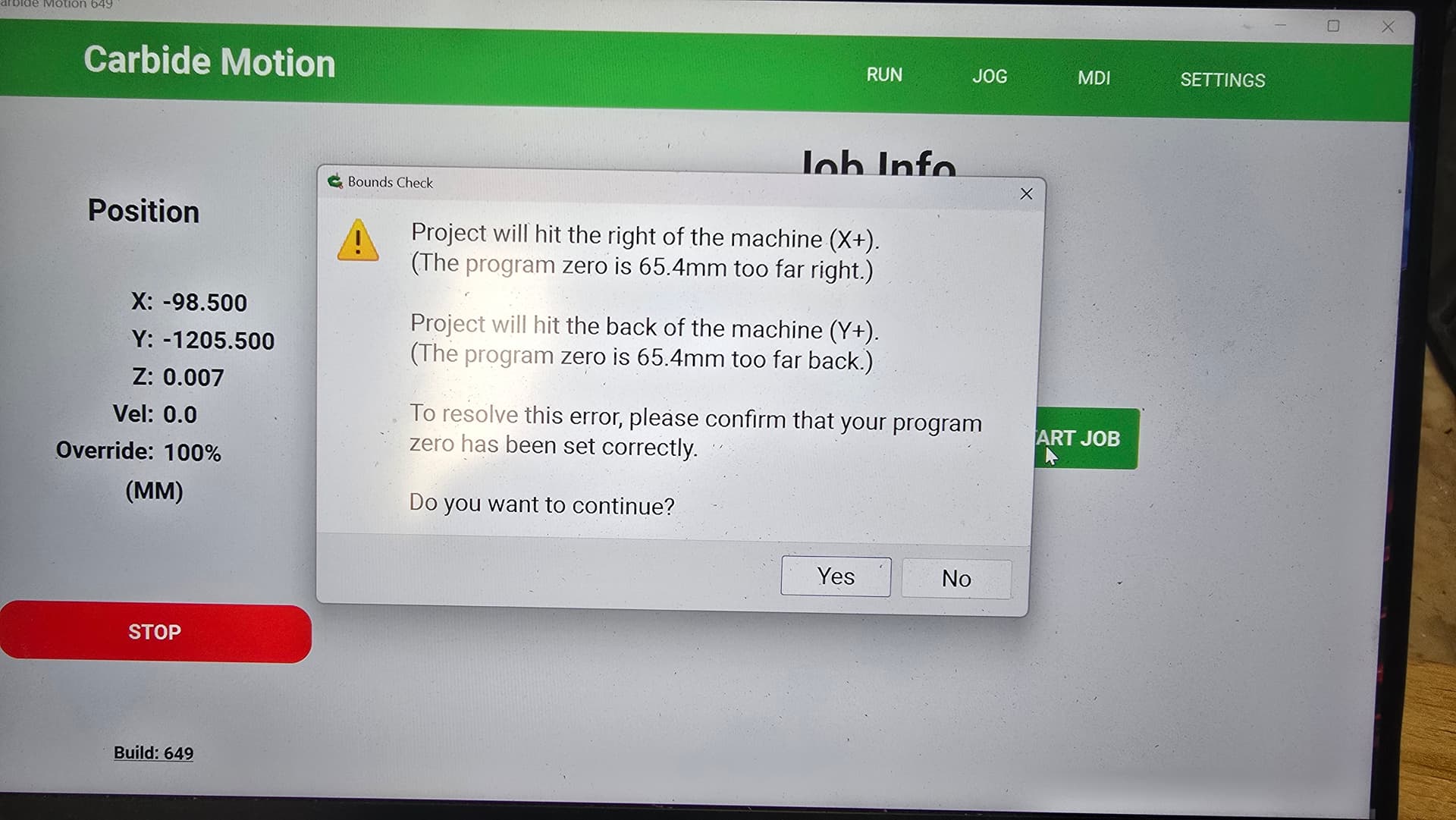
If I bypass this warning, the machine starts and always goes to the right back corner, although I set it up front, left, or center. The spindle is sitting too high, but still simulates making a circular motion

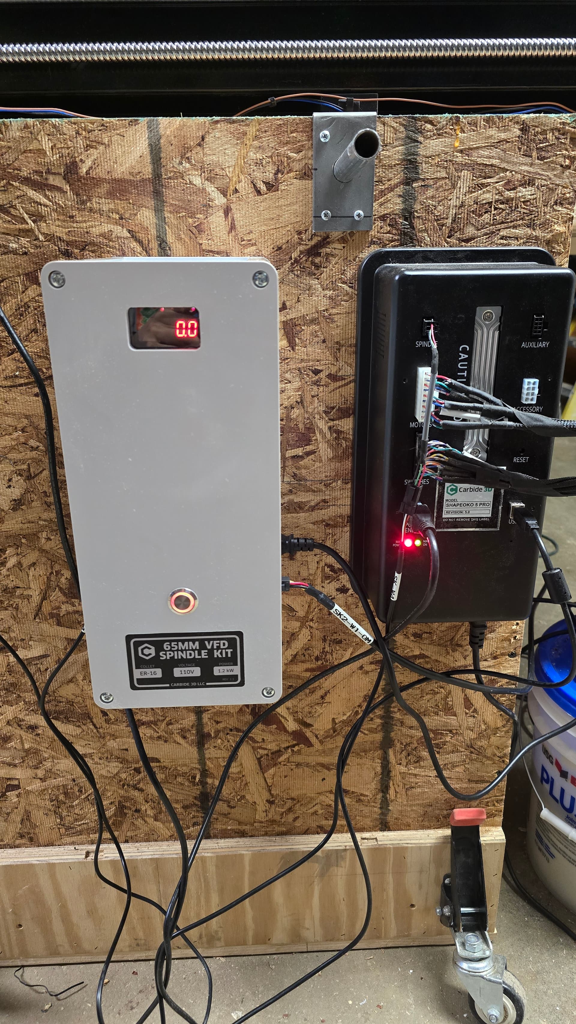
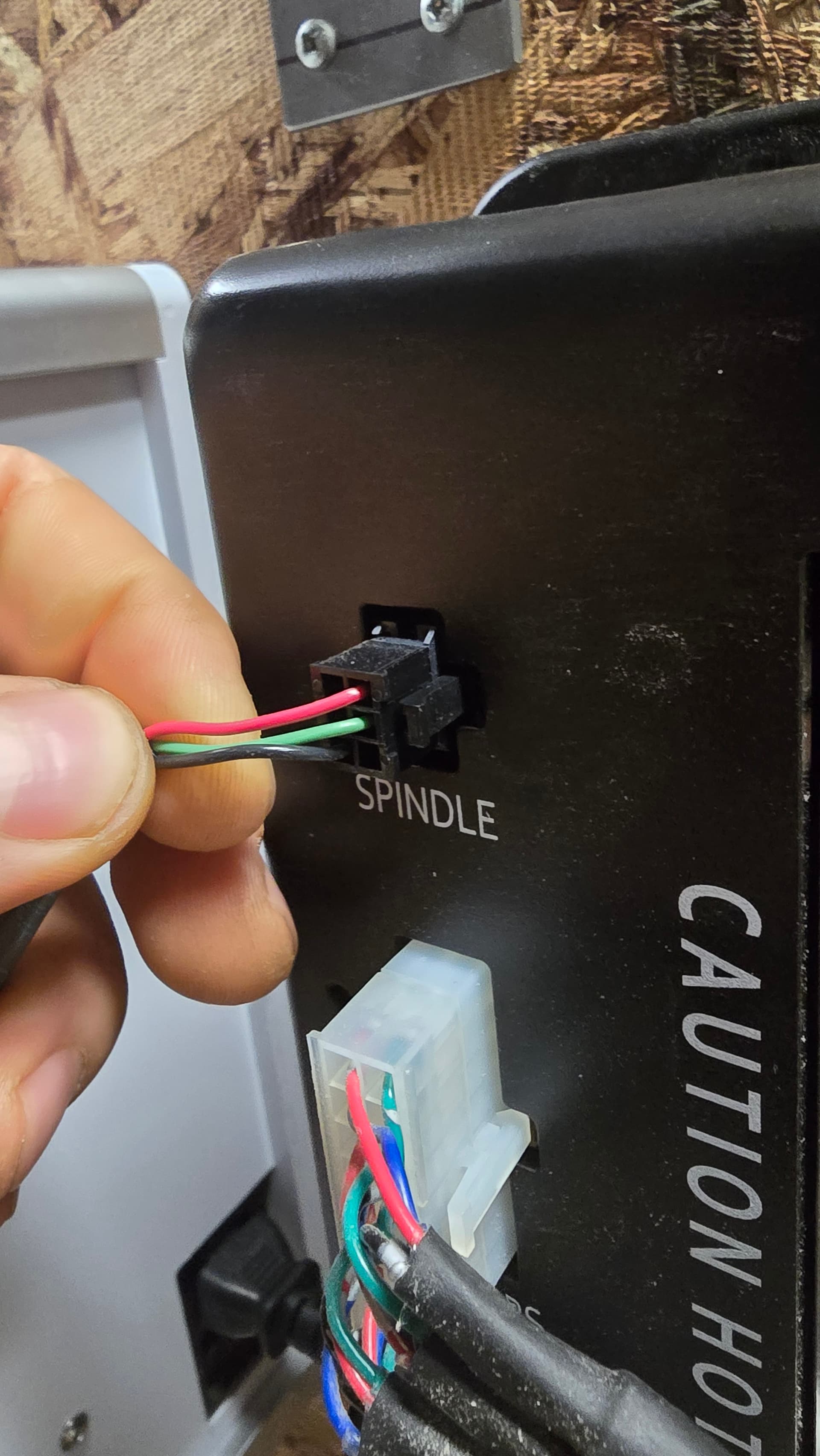
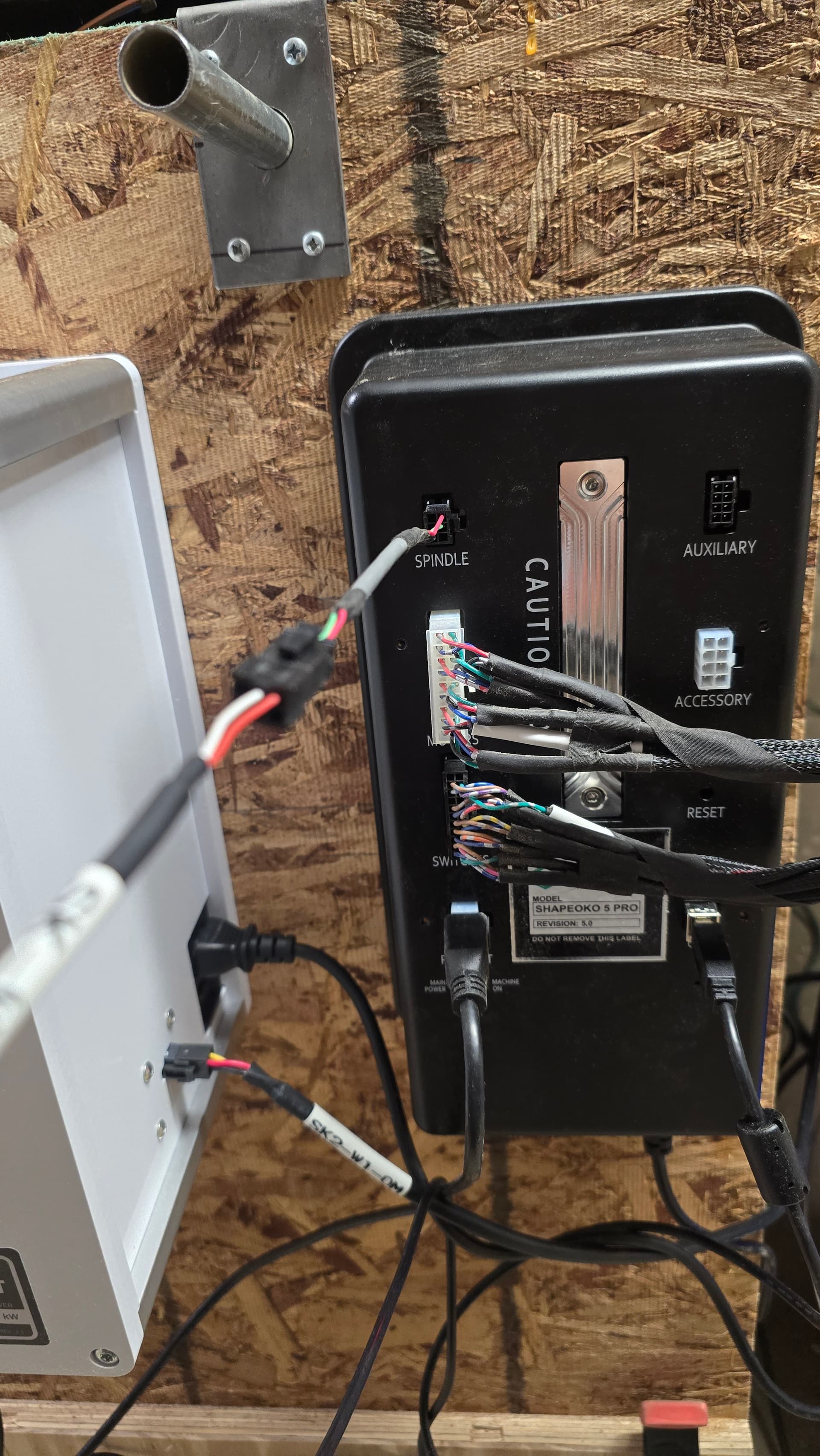
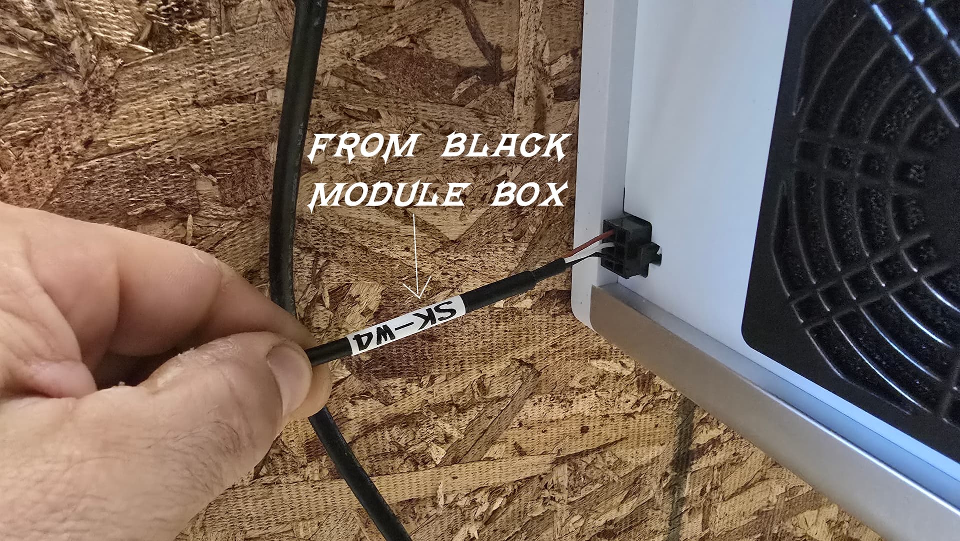
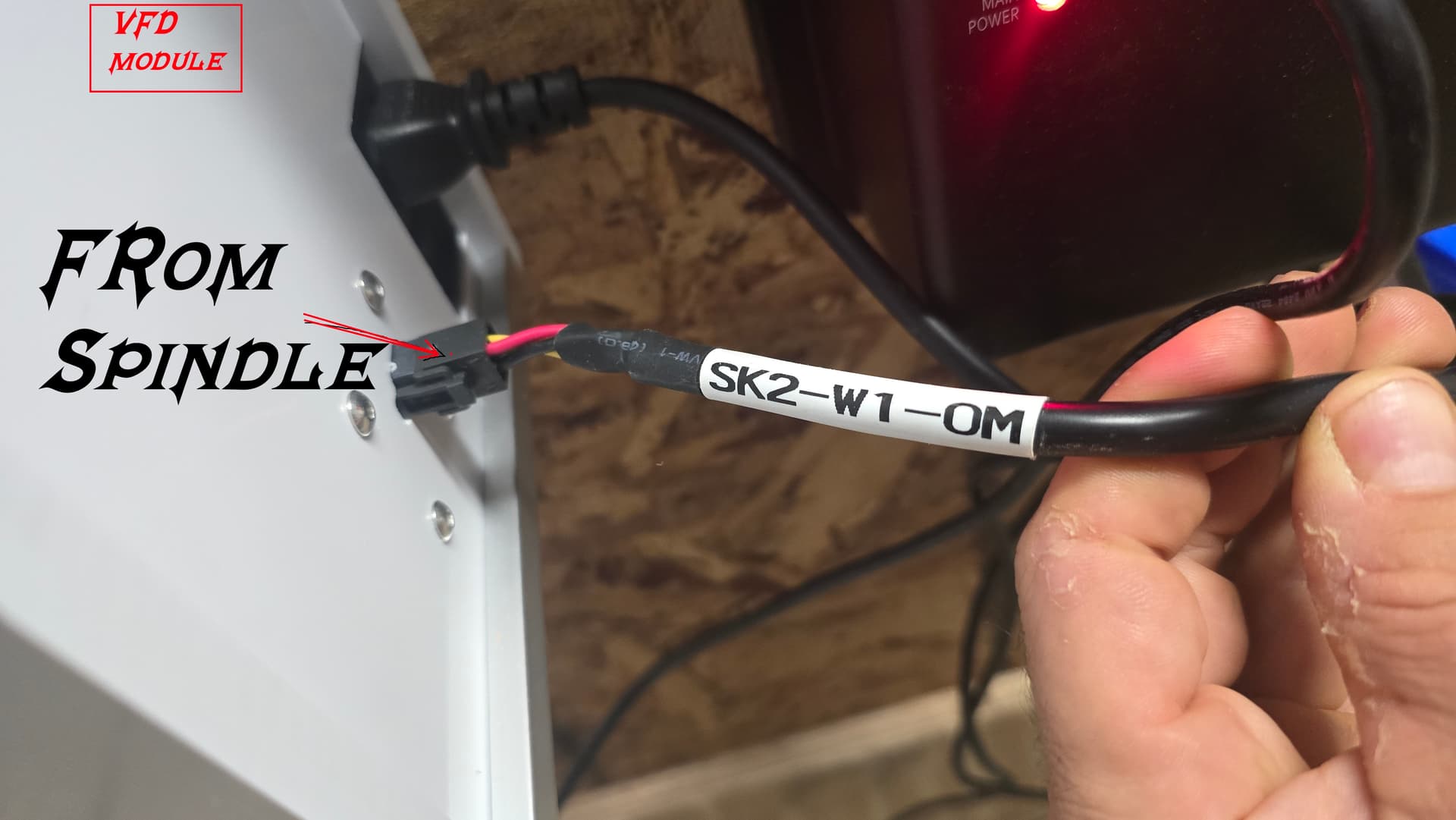
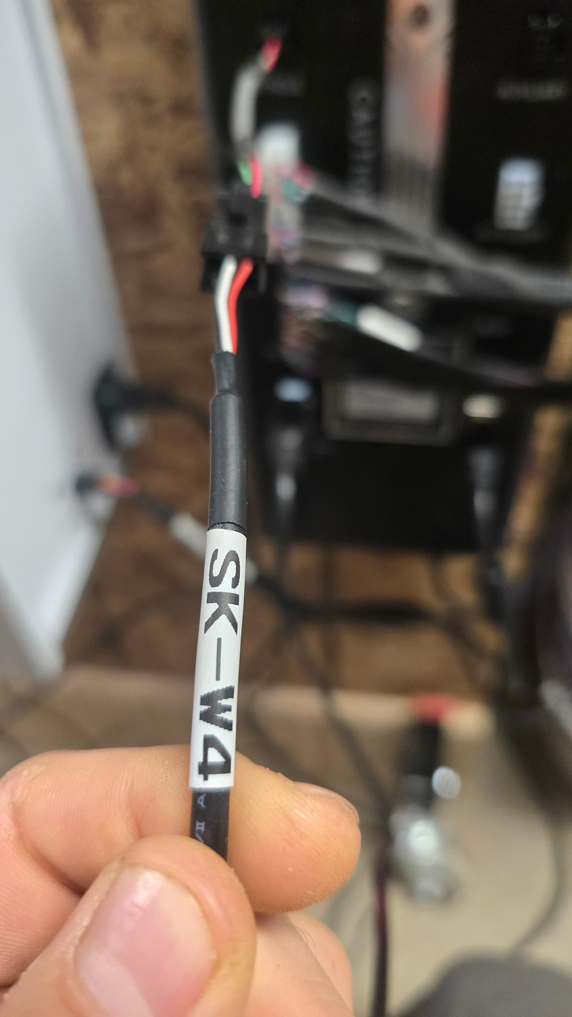
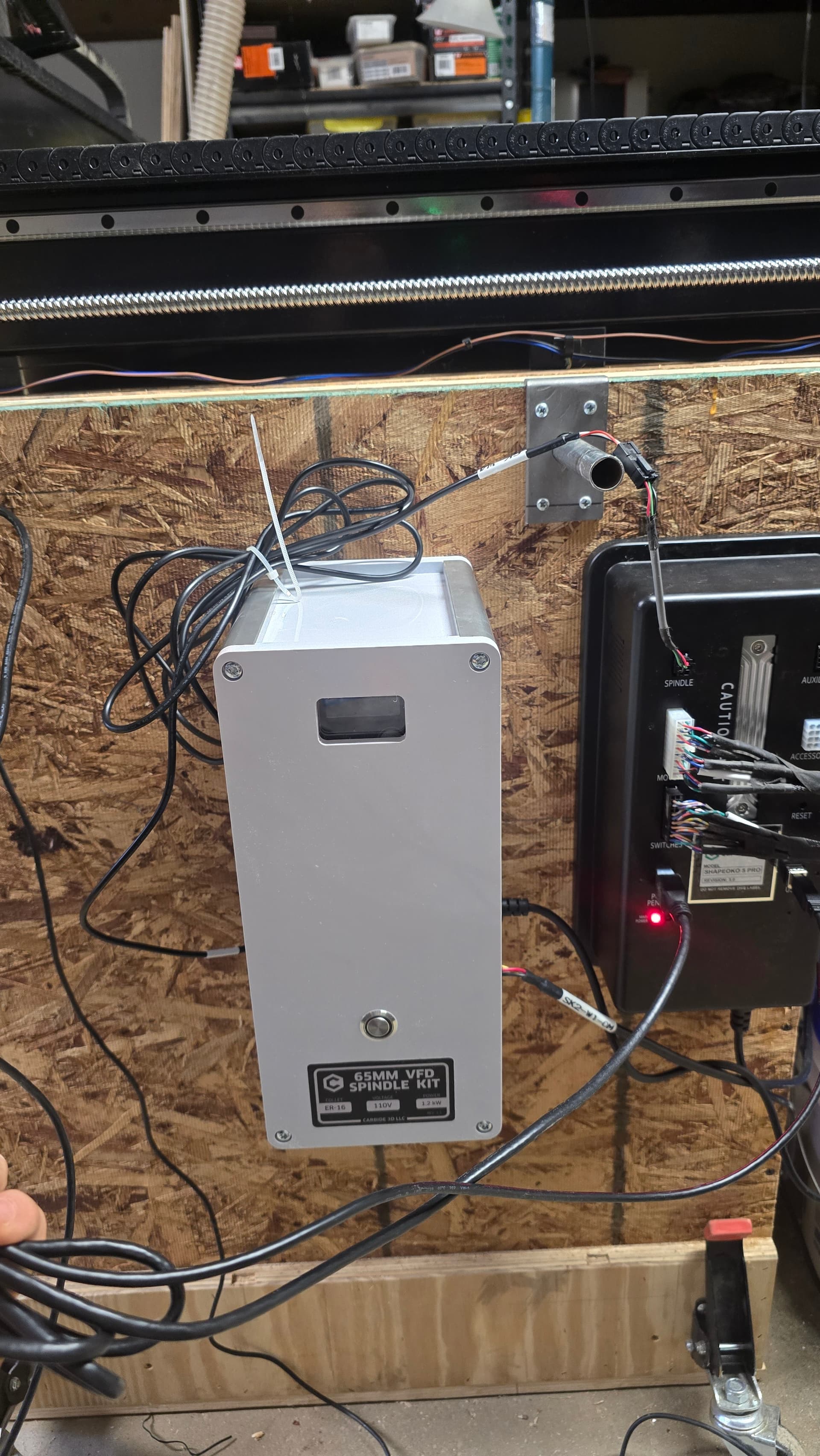
The VFD Spindle is not spinning at all - not in a task, not in a warmup test, the button is pressed, and the red ring around is light on, just 2 flashing 0.0 on the red display of the VFD module

And last, when the machine initialized the home or zero-s, I don`t know what, moving just fine
Or randomly left, right, center, or any corner in the test page, but when I load a task and start going to the right back corner, it vibrates as if it’s not a proper square or aligned if it’s not a task, same patch, but not vibrations.

This is a warning as noted at: Carbide Motion Bounds Checking Usually it is caused by a mismatch between job setup: Job Setup and how origin is set relative to the stock: Movements and Zeroing — I find that opening the .c2d file up and drawing a box which matches the specified dimensions (draw up the cut in profile if need be) or moving the machine to the origin and then using a tape measure to measure out the dimension(s) in question will make clear where things aren’t lining up.

If you still have trouble, please send in the .c2d file to support@carbide3d.com and let us know step-by-step how you are securing your stock and setting zero relative to it and managing all tool changes, and send a photo showing the stock in place and the machine at the zero position relative to it (or a specified offset from that position) and screengrabs showing what Carbide Motion shows for Position and Machine Position (click on either to toggle to the other).

For the spindle not starting up, that’s usually a problem with how things are connected/wired up — the folks at support@carbide3d.com should be able to assist with that.

2 Likes

Your answer helps me a lot. I understand something fundamental for this CNC machine - I have to set up the zero of every single piece. I set it up on the table and choose a pivot point, either the corner or the middle, because the machine doesn’t know where the piece is on the table. And with the help of this clip a connect the dots: https://www.youtube.com/watch?v=QxvC85OXc48 . I am a 3D printer user till now and was expecting for more automated machine. Like the machine knows the size of its table, and when I create a file, my setup is to start in the left corner and move 200mm, I will move 200mm, and that’s it. But this one works differently from 3D printers - Anyway - that’s all good, but the VFD Spindle is not spinning, and that’s a problem !!!

We do have folks who use the machines as you describe — they draw up their machine as described at:

set the origin once, then lay out files using the original as a template and never set zero again.

If you haven’t contacted support yet, please do so — the folks in Chicago and on the west coast will be waking up soon, and mostly the folks who handle the SO5 Pro and VFDs are on that side of the country.

Yes, I will call them shortly. In the meantime, I will post how the VFD is connected so I can get a better understanding before making the next rookie mistake

This cable has 3 wires. The pins are 6 … the only other cable that is the same and I have is for a power pendant, but the power pendant (start button and pause) is not working with 3 wire cable

You have the updated version of the 65mm spindle, that said the pinout from the C3D controller is the same configuration as my original based on your photos. So that looks like it’s configured correctly on your machine. The VFD to spindle pwr/control is different it seems. My version is hardwired and I cannot confirm pinout without opening up the VFD enclosure.

When providing troubleshooting photos please show the cable label in the photo as best you can.

I spoke with customer service on the phone, and we did some tests on the machine, and they decided to replace the main module (the motherboard of the machine, black box). Now waiting for the replacement and will see what’s going to happen. Thanks to all for the immediate help.

1 Like

This topic was automatically closed after 30 days. New replies are no longer allowed.