Okay, I have run the test again.
Observations:
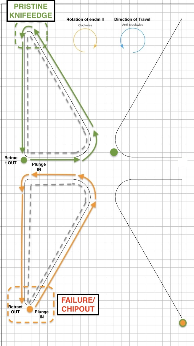
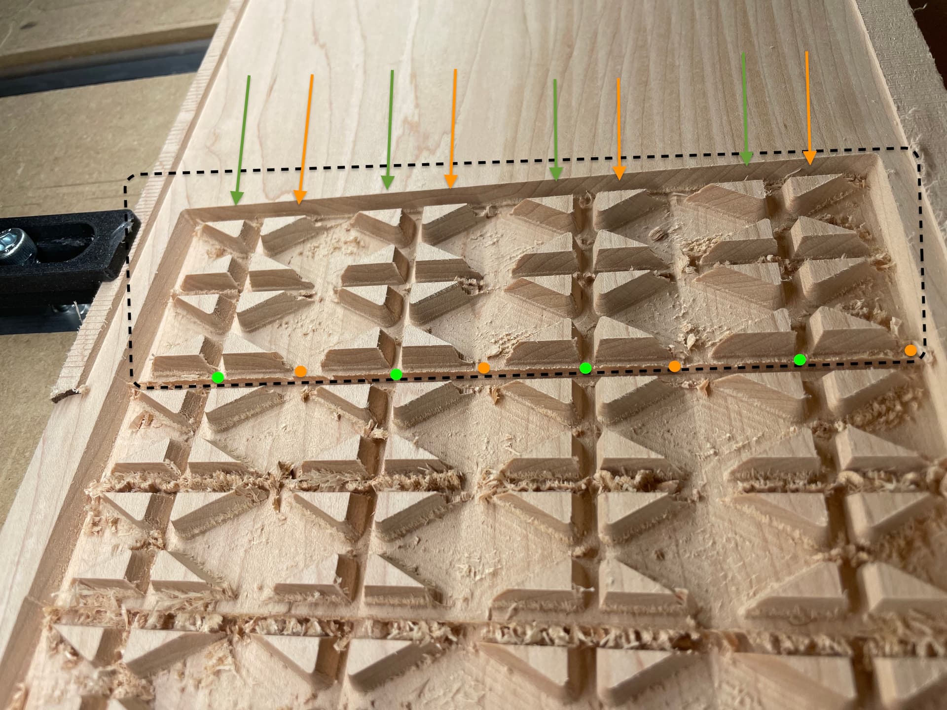
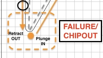
Orange - the failure example:
- Tool enters cut at fragile tip. No damage is caused at this point.
- Tool goes anticlockwise all the way around the perimeter of the shape with the vbit. No damage still
- Tool is coming up to the fragile tip to finish off the cut. The motion of the tool shaving off chips clockwise (away) from the material core (while the other side of the fragile tip was already removed in 1) chips and damages it.
Orange Cause - The combination of:
- Half the fragile tip’s taper backing support stock-to-leave being removed by the vbit on the tip → increasing material engagment portion of the pass prior to the other half of the fragile tip cut (the approach of increasingly disengaging the material to end on the tip); compounded by…
- …the clockwise motion of the endmill cut
…come together in an unholy combination causing the knife edge of the delicate taper tip being chipped off.
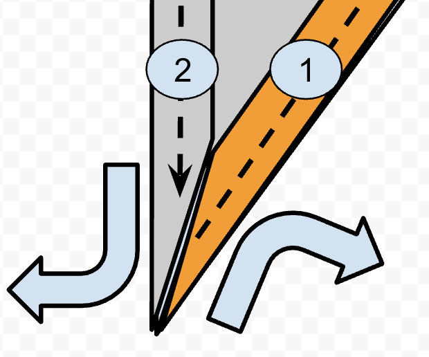
Figure - #1 and #2 represent the first and second cut order, Orange shading indicates where material is removed from tip section first; Grey shading where material still remains after 1st half of taper tip cut; Large outward blue arrows represent endmill cutting rotation; black dotted arrows indicate the spindle direction of travel; Small blue slither at the knifedge is the thin taper feature of the inlay that keeps getting chipped.
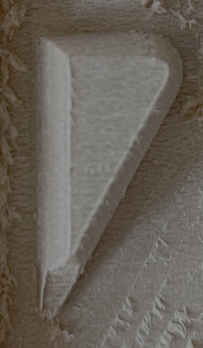
Green - the pristine example:
- Tool enters cut AWAY from fragile tip. No damage.
- Tool goes anticlockwise all the way around the perimeter of the shape with the vbit. No damage still
- Tool approaches the fragile taper tip segment BUT it still has all the stock-to-leave backing material so is fully supported. The motion of the tool shaving off chips clockwise (away) from the material core doesn’t chip because the tip feature is not thin enough to a taper knife edge at this stage, unlike ORANGE.
Green Cause: As the tool comes back into the material after reaching the tip and creating half the taper knife-edge, you would think it would have the same chipout behaviour at this point because the material removal from 3. However, the key difference is the spindle direction of travel is into increasing greater material engagement. Therefore, although the endmill is still spinning clockwise and creating the knife edge, it’s creating the knife edge while moving into increasingly more material and away from the fragile taper knife edge, preventing the chipping, rather than creating the knife edge while reducing material engagement to just the knifeedge tip which radically increase chipout potential.
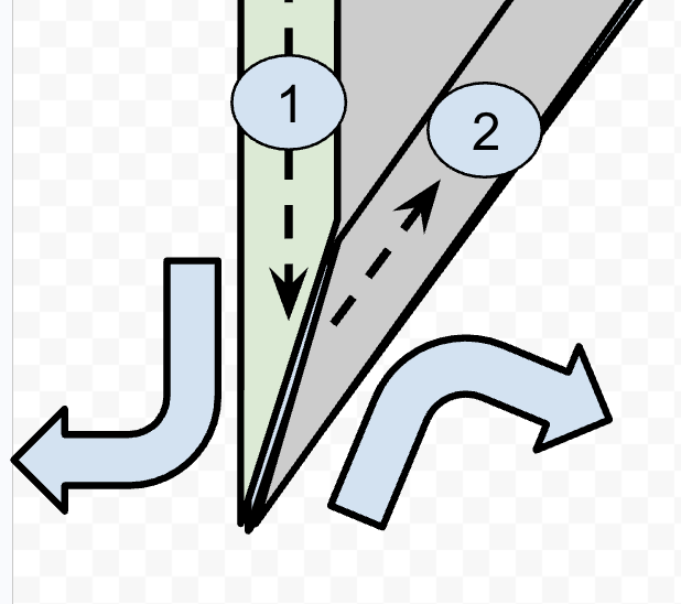
Figure - #1 and #2 represent the first and second cut order. Green shading indicates where material is removed from tip section first; Grey shading where material still remains after 1st half of taper tip cut; Large outward blue arrows represent endmill cutting rotation; black dotted arrows indicate the spindle direction of travel; Small blue slither at the knife-edge is the thin taper feature of the inlay that is preserved in this scenario.
Conclusion:
Tool start/end position is 100% the cause of this fine detail chipping issue with CC advanced vcarve toolpath. It’s not specifically the active motion of the plunge in or the retract out BUT it is 100% the entry and exit position set on on the fragile tip that leads to the conditions of terrible stock removal order which is aliased by the entry/exit point POSITION that is causing this.
Proposed Possible Solutions:
-
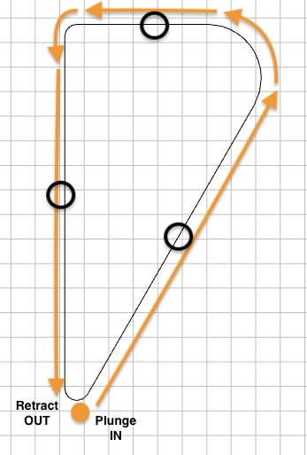
Change SW to reposition automagically the entry/exit point as you do already but instead of setting bottom-left corner by default, place AWAY entirely from any tip (perhaps the rough middle of a perimeter is most simple to blanket implement without introducing absolute units as could be programatically determined by taking the average between 2 corner nodes to get middle of perimeter line?). Represented as black circles in the image below for visual aid.
-
…OR make the above a less blanket solution if preferred by setting a param to never start on any tips with acute angle of <45 or <60deg as these are the problematic breakpoint angles this entire topic is about anyway, so has more precision focus (hybrid of current default for certain angle range)
-
…OR as little as ‘From current default entry/exit position we use in CC, add a param to simply shift/offset them all like 20mm clockwise’ so it has the same causal effect as green success scenario with minimal development? (Represented as black circle in the image below for visual aid). I can see there being problematic edge cases occurring because it introduces absolute distance values to the mix rather than programmatically generated, unless you can think of a programmatic way to do this. Would be simpler to implement (1) probably.
-
[MOST VERSATILE]…OR/AND create a UI option in the SW so the user can select the entry/exit position node as @Pchuk mentions above - This is probably the most versatile fix to resolve for all edge cases. Could be laid out like your current ‘edit nodes’ UI but for selecting the entry/exit point, so can cannibalise a feature you already have
Additional Related Suggestions:
- Consider also implementing in addition what @Tod1d said about the option to select between conventional or climb milling for advanced vcarve like he mentions you can for contour cuts. That would probably be a compounding factor along with the above suggestion that could perhaps help make the above strategy even more effective; to protect super shallow angle point knifeedges and make the whole thing more forgiving. I personally don’t know for sure as i can only show you my physical results with what I can demo in your SW currently but keep it in mind.
- More a side thought hypothesis - Another hypothetical improvement which I can’t test but maybe could also help improve the toolpath and I share just to get the C3D juices flowing - perhaps also update the carve to slow the feedrate down to 60% speed on fragile <45deg or <60 deg angle taper tip features?