Way to Improve Carbide Create Inlay VCarves in Facegrain

Motivation - I CBA with endgrain. It’s long to prepare and annoys me. I want to use facegrain.

Context:
Machine - shapeoko 5 (4x4) + 80mm water cool C3D spindle.
CC version - 835
CM version - 651

I have been playing around with inlays alot and more recently focused on deep 6mm facegrain ones with a 30 degree vbit. I have found that the procedure is great for stuff with no long and thin details but I want to be able to use this for the style of inlays you see online that are more intricate and organic but do so on facegrain.

I’m running a battery of MALE inlay tests atm and I am noticing something interesting with your vcarve procedure that is causing unnecessary, repeated failures from chipout. On the long, thin details, some of them come out pristine and some of them come out mildly to majorly chipped out.

What I noticed:
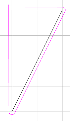
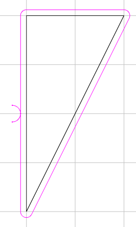
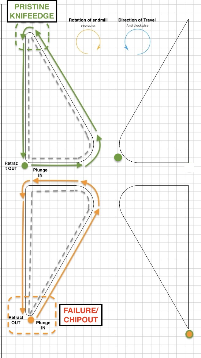
on those where the endmill plunges into the material at the very tip of the fragile detail, it typically shows signs of mild to major chipout (therefore failure) even with very conservative settings. However, those exact same details which are oriented 180 the other way round (and I observed the plunge position therefore to shift to be away from the tip of the fragile detail tip), they are almost pristine.
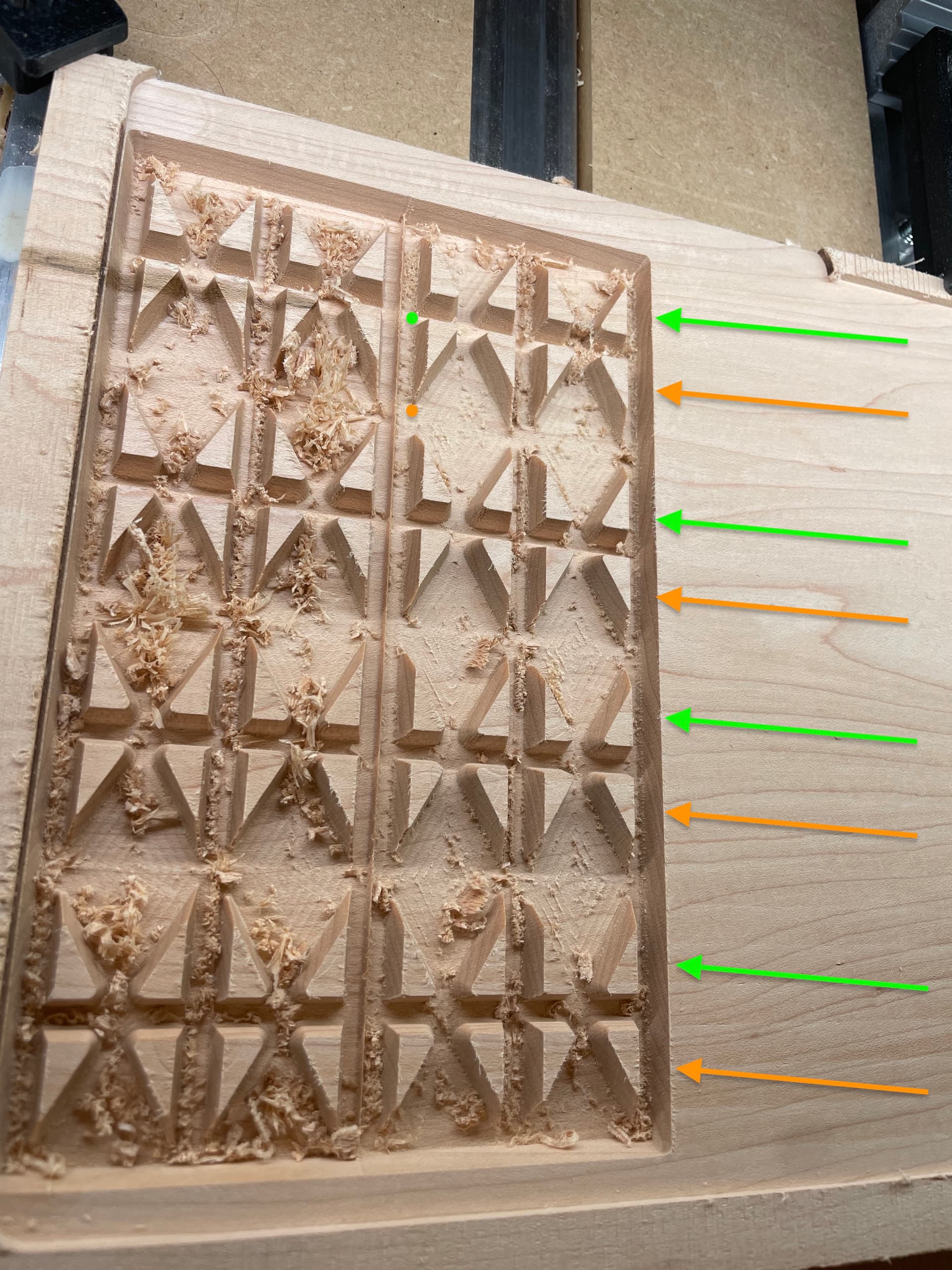
Photos:
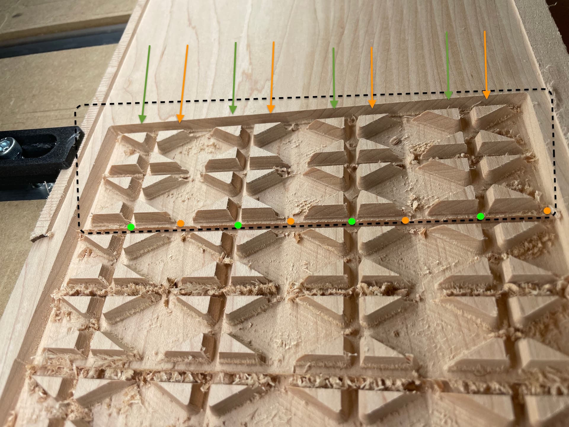
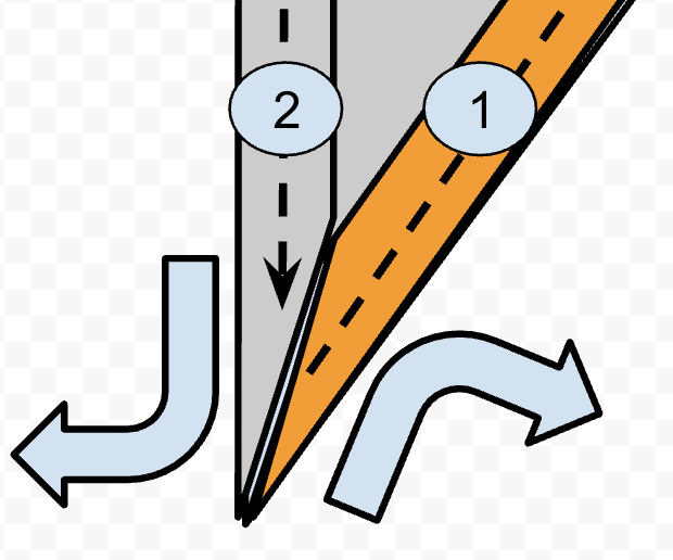
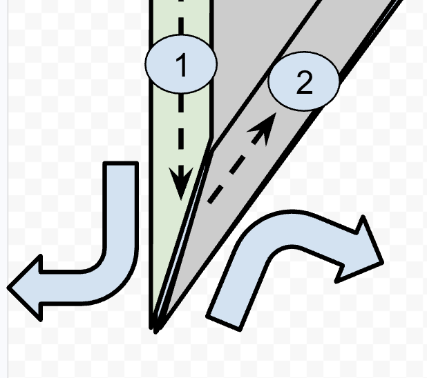
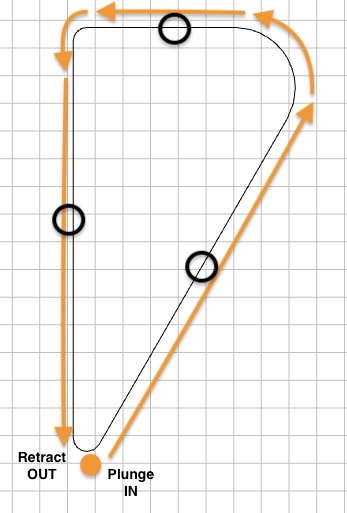
Green arrow rows (Where fragile detail faces UPwards) - these are the consistently the pristine ones.
Green dot (Plunge entry point) - the observed entry plunge position on ALL the pristine ones.

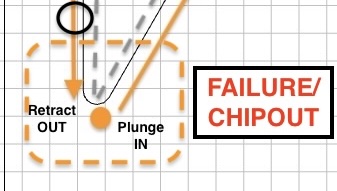
Orange Arrow rows (Where fragile detail faces DOWNwards) - these are consistently the chipped ones.
Orange dot (Plunge entry point) - the observed entry plunge position on ALL the chipped ones ones.

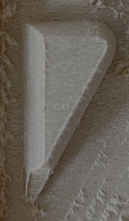
Photo of part of Test batch 1:
Material - tulipwood (poplar for the yanks)
~600 janka hardness so would expect higher probability of chipout. Started with this because I had it ready to hand for quick vibe test a variety of different approaches to establish a procedure for myself to make facegrain inlays. I tested a variety of different approaches but there was one consistent trend that came out no matter what extreme or conservative approach I took. I noticed a pattern toward end of my tests.

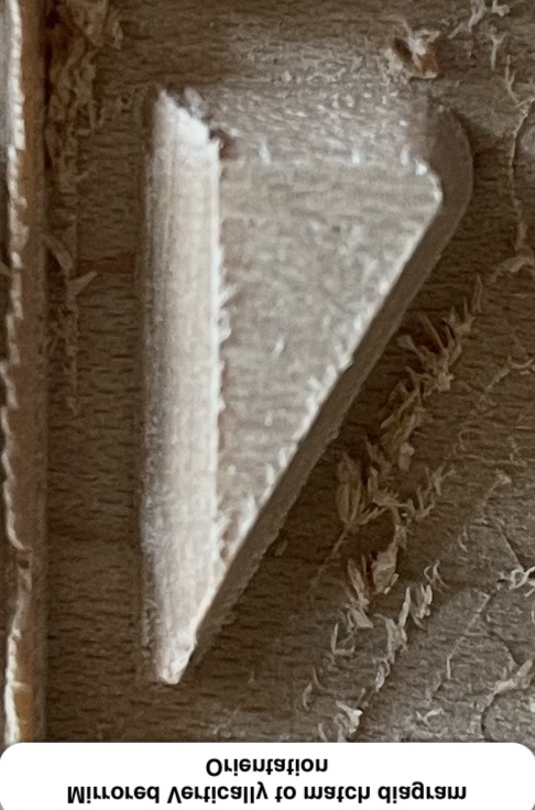
Photo of Test batch 2:
Material - Maple
~1500 Janka hardness so should eliminate the variable of hardness being a contributory factor. The issue persists on this wood too so there’s something else at play. Here, the results were a bit improved but the pattern still persisted where the one faceing upward are 100% pristine and the ones face 180deg downward, a number of them were chipped still

Observation
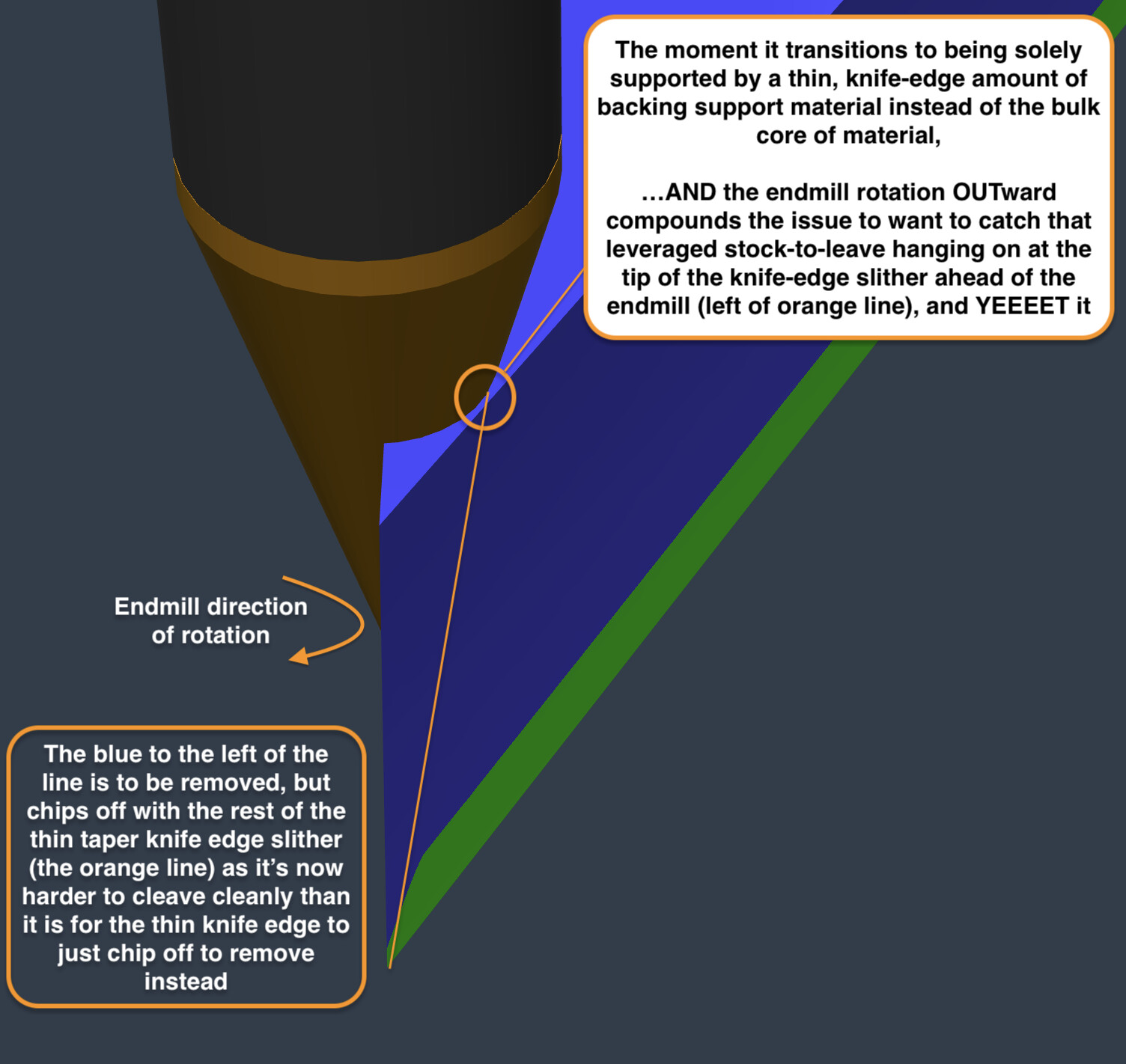
Notice how the chipout is all happening primarily on the ones where the tool plunges at the tip of the fragile detail and the other that doesn’t plunge at the fragile tip is regularly pristine and undamaged?

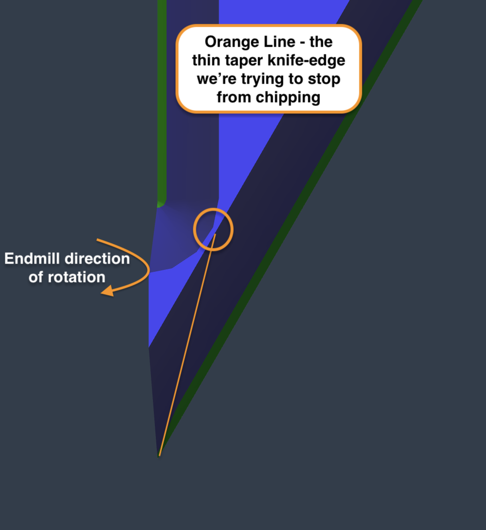
Proposed improvement:
This is a software thing that will consistently stop me from attempting pristine detailed facegrain inlays and is out of my control to solve as a user, so i suggest the following dev fix to try out:

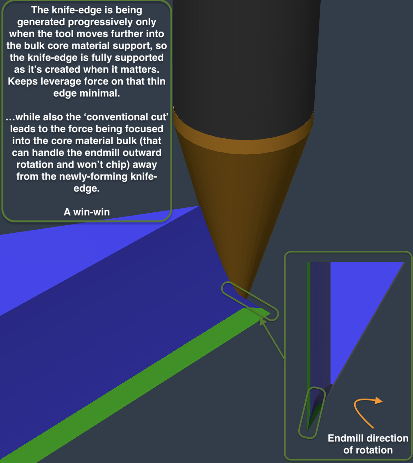
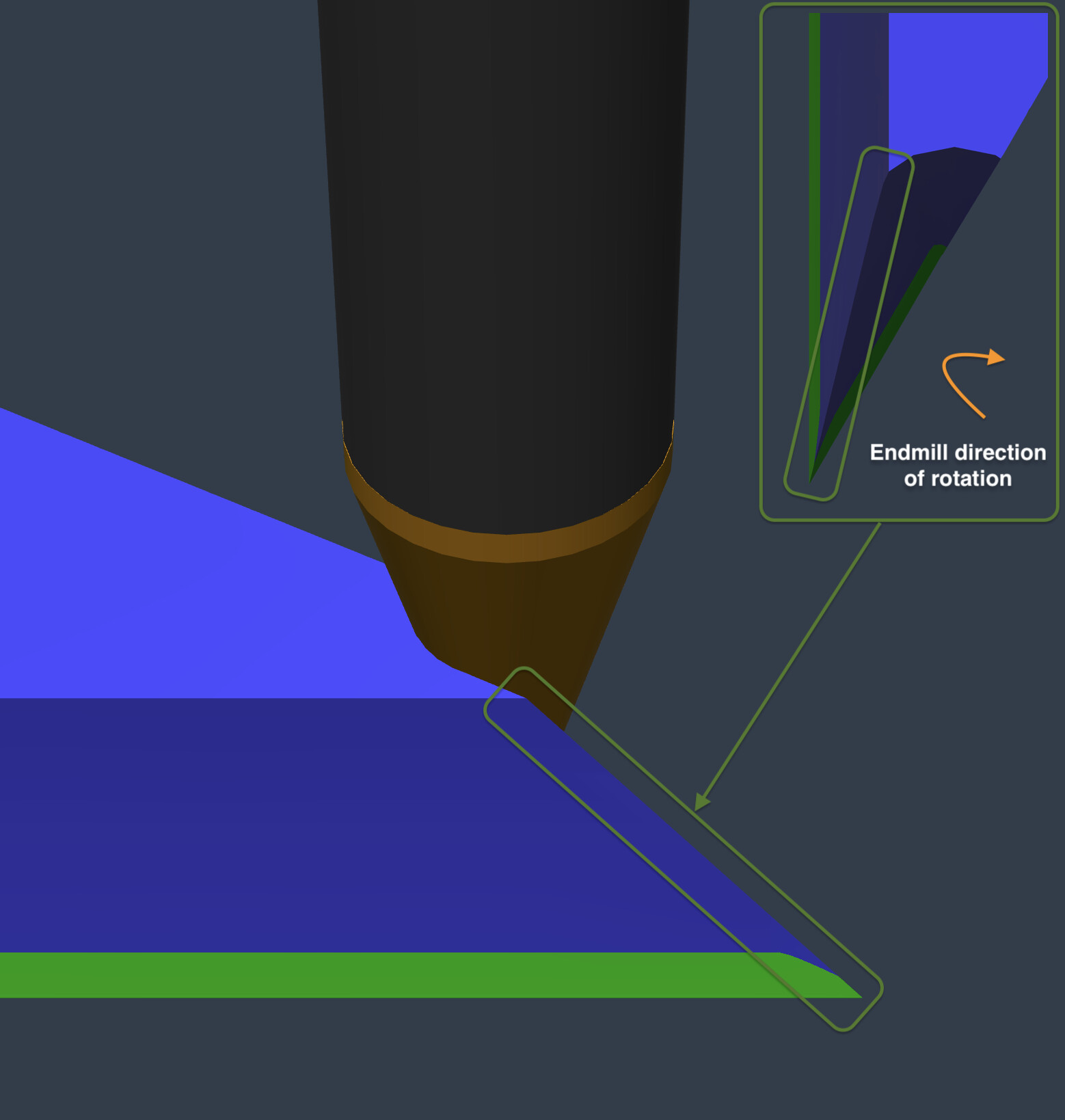
  • Please make the plunge position be away from any pointy tips; Into the midsection of a consistent wall works great instead - Are you able to update your inlay toolpath to incorporate a condition where it avoids entering in at the tip of of a detail and instead always enters away from the tip of a detail,
  • If not, a less ideal alternative would be to tell it to only ever enter in at the tip of a detail if that tip is the peak of a >45 degree angle (ideally higher like closer to 60 minimum but just giving you a param to set to bare minimum)
  • Problems occur most primarily where the detail tip is an acute angle of 45 degrees or less (ideally 60 would be bare minimum imo but if possible to make it higher, great) - This angle specifically because, beyond what I suggested above being an observation of repeat failure, that angle threshold is a breakpoint that always most prone to screwing up from many past failures.
  • side observation - The length to which the fragile tip takes to taper is also a factor (i.e. if its only 1cm to taper to the point rather than 2cm to taper, the thin feature is more likely to survive) but I think the above ‘acute angle rule’ I’ve described would go some way to also solving for this as typically the taper is longer to very acute angles 45deg compared to could encompass this factor

It is not 100% effective but, when i compare the results between batch tests, there is a clear and present obvious improvement where, if i were to give a general ‘vibes’ ratio, the chipout failures are far less frequent (>90-95% it works) but also more minor if they do happen than the ones where the tool enters right at the tip. It’s night and day difference to me.

I’ve always had little issues like this for years but never had the focus to really pin point the issue. This is the first time I’ve picked up and isolated plunge position as a variable as opposed to the standard things you look at. The features in the tests above are exactly the same as the one next to it, except flipped 180degrees.

Another hypothetical improvement which I can’t test but maybe could also help improve the toolpath and I share just to get the C3D juices flowing - perhaps also update the carve to slow the feedrate down to 60% speed on male fragile <45deg or <60 deg angle tip features?

3 Likes

Does the chipout happen during the plunge, or after the plunge when it starts to move?
Or is it at the end of the cut right before the retract?
Have you tried running the V-bit first?

Hey Tod,

I can rerun the test again today and see the outcome and feedback to you as I can see how that would be helpful granular data to have for making the solution. At the very least, my results show there is an issue with plunge position enough for me to think it worth raising to ya’ll.

I have tried running vbit first but the problem is 2-fold:

  1. its super slow as you have to go 1mm deep max with 30deg and
  2. the vbit always reliably breaks on me and I hate the anxiety of ‘did I make sure my stock is flat enough or clamped enough not to cause it to snap this time doing full slot cuts?’.

I hate both these factors so I’m looking for a better way.

Key Information:
I also find it’s not particularly necessary to run the vbit first for many parts of my facegrain inlays; Most the time, I can do cuts with clearance endmill first with zero issue. it’s only where the angle is acute (~<45 or <60deg) have I noticed it particularly matters for chipout concerns which is what i’ve been doing my testing to try to solve, and discovered this phenomenon on my inlay-obsessive travels

Tobby [sic],

One problem with CC is it wants to conventional cut everything. They added the option to climb cut on contour paths, but pockets & Vcarves still want to conventional cut.
The direction your grain is running makes those sharp corners susceptible to chipping.
Short of using a software that allows more control, you could draw in the V-carve paths as open vectors so they start at a point of your choosing, and you can control the direction.

OR

Tod (with 1 ‘d’) :wink:

3 Likes

I will keep that more manual, workaround approach in mind :hand_with_index_finger_and_thumb_crossed:

Grain direction should be constant - Regarding grain direction being a factor, the only real difference in the test features milled is either they are facing up or facing down, so the grain direction should ultimately be as exactly the same as you could possible ask for a natural wood material in a practical scenario (i.e. both are across the grain 90 degree perpendicular to eachother), so I feel like the tests above go some way to keeping that factor as constant as you can expect from a natural material.

Conventional cut is constant - you are probably right regarding the conventional vs climb too. If what you are saying about CC conventional cutting everything is true, that’ great to know as that means it is a constant in these tests too.

Conclusion - When you really scrutinise it, the only real difference between I can come to in the results was the plunge position (if you assume what i say about plunge position consistency is true). I’ll run again tonight and feed back. Hence why It would be interesting for C3D to try out and implement as a systemic fix if they consistently see what I see.

This probably applies to both male and female parts where the material comes to a point and the angle of said material come to a point of 60degree or less, but i’ve primarily focused on male experiments based on my need. It’s not when its a pocket of machined out material of <60deg, it’s when the only material left is 60 deg (like the images above) in case this was unclear, as i am blabbering alot

@tobwhy I’m not sure if it’s possible in CC like it is in VCarve Pro, can you select the Node that you want each vector to start at?

You can’t iirc - That would be an awesome feature to add if C3d decide it better to outsource this solution to the user to control instead of doing it blanket as above. You raise a really interesting point for the feature request to consider that might be easier for C3D to implement than what i’m suggesting. No idea if its easier but, logically thinking, it might be so thanks for that valuable input!

1 Like

Okay, I have run the test again.

Observations:

Orange - the failure example:

  1. Tool enters cut at fragile tip. No damage is caused at this point.
  2. Tool goes anticlockwise all the way around the perimeter of the shape with the vbit. No damage still
  3. Tool is coming up to the fragile tip to finish off the cut. The motion of the tool shaving off chips clockwise (away) from the material core (while the other side of the fragile tip was already removed in 1) chips and damages it.

Orange Cause - The combination of:

  1. Half the fragile tip’s taper backing support stock-to-leave being removed by the vbit on the tip → increasing material engagment portion of the pass prior to the other half of the fragile tip cut (the approach of increasingly disengaging the material to end on the tip); compounded by…
  2. …the clockwise motion of the endmill cut
    …come together in an unholy combination causing the knife edge of the delicate taper tip being chipped off.

    Figure - #1 and #2 represent the first and second cut order, Orange shading indicates where material is removed from tip section first; Grey shading where material still remains after 1st half of taper tip cut; Large outward blue arrows represent endmill cutting rotation; black dotted arrows indicate the spindle direction of travel; Small blue slither at the knifedge is the thin taper feature of the inlay that keeps getting chipped.

Green - the pristine example:

  1. Tool enters cut AWAY from fragile tip. No damage.
  2. Tool goes anticlockwise all the way around the perimeter of the shape with the vbit. No damage still
  3. Tool approaches the fragile taper tip segment BUT it still has all the stock-to-leave backing material so is fully supported. The motion of the tool shaving off chips clockwise (away) from the material core doesn’t chip because the tip feature is not thin enough to a taper knife edge at this stage, unlike ORANGE.

Green Cause: As the tool comes back into the material after reaching the tip and creating half the taper knife-edge, you would think it would have the same chipout behaviour at this point because the material removal from 3. However, the key difference is the spindle direction of travel is into increasing greater material engagement. Therefore, although the endmill is still spinning clockwise and creating the knife edge, it’s creating the knife edge while moving into increasingly more material and away from the fragile taper knife edge, preventing the chipping, rather than creating the knife edge while reducing material engagement to just the knifeedge tip which radically increase chipout potential.

Figure - #1 and #2 represent the first and second cut order. Green shading indicates where material is removed from tip section first; Grey shading where material still remains after 1st half of taper tip cut; Large outward blue arrows represent endmill cutting rotation; black dotted arrows indicate the spindle direction of travel; Small blue slither at the knife-edge is the thin taper feature of the inlay that is preserved in this scenario.

Conclusion:
Tool start/end position is 100% the cause of this fine detail chipping issue with CC advanced vcarve toolpath
. It’s not specifically the active motion of the plunge in or the retract out BUT it is 100% the entry and exit position set on on the fragile tip that leads to the conditions of terrible stock removal order which is aliased by the entry/exit point POSITION that is causing this.

Proposed Possible Solutions:

  1. Change SW to reposition automagically the entry/exit point as you do already but instead of setting bottom-left corner by default, place AWAY entirely from any tip (perhaps the rough middle of a perimeter is most simple to blanket implement without introducing absolute units as could be programatically determined by taking the average between 2 corner nodes to get middle of perimeter line?). Represented as black circles in the image below for visual aid.

  2. …OR make the above a less blanket solution if preferred by setting a param to never start on any tips with acute angle of <45 or <60deg as these are the problematic breakpoint angles this entire topic is about anyway, so has more precision focus (hybrid of current default for certain angle range)

  3. …OR as little as ‘From current default entry/exit position we use in CC, add a param to simply shift/offset them all like 20mm clockwise’ so it has the same causal effect as green success scenario with minimal development? (Represented as black circle in the image below for visual aid). I can see there being problematic edge cases occurring because it introduces absolute distance values to the mix rather than programmatically generated, unless you can think of a programmatic way to do this. Would be simpler to implement (1) probably.

  4. [MOST VERSATILE]…OR/AND create a UI option in the SW so the user can select the entry/exit position node as @Pchuk mentions above - This is probably the most versatile fix to resolve for all edge cases. Could be laid out like your current ‘edit nodes’ UI but for selecting the entry/exit point, so can cannibalise a feature you already have

Additional Related Suggestions:

  1. Consider also implementing in addition what @Tod1d said about the option to select between conventional or climb milling for advanced vcarve like he mentions you can for contour cuts. That would probably be a compounding factor along with the above suggestion that could perhaps help make the above strategy even more effective; to protect super shallow angle point knifeedges and make the whole thing more forgiving. I personally don’t know for sure as i can only show you my physical results with what I can demo in your SW currently but keep it in mind.
  2. More a side thought hypothesis - Another hypothetical improvement which I can’t test but maybe could also help improve the toolpath and I share just to get the C3D juices flowing - perhaps also update the carve to slow the feedrate down to 60% speed on fragile <45deg or <60 deg angle taper tip features?
2 Likes

Key Takeaway:
Since it’s conventional cut, Ensure both halves of the tip is fully cut immediately in one continuous swoop; do not allow the cut to start half way through it (i.e. parachute in at the tip itself), cut half of it, and then do the other half later because it will be unsupported in the conventional cut (which is spinning outward away from the material core and will yeet the entire taper knife edge into mount doom as a chip because theres only a knife-edge slither of material left which can’t take the strain and is weaker than the force to cleave the chip away clean - so it all comes away instead.

Positioning literally anywhere else except for right on the tip node of the corner to enter/exit the cut solves for this; even if its literally just before the corner - just don’t divide the corner into 2 halves by entering right at the tip. Also, less critical but potentially reduces chances of chipout further by providing the option to swapping to climb-cutting but I haven’t verified this - certainly theoretically sounds like it might help be more forgiving but would require testing

Current:

Proposed:

C3D - please seriously consider this feature request applied to both the ‘advanced vcarve - endmill and vbit’ toolpaths to promote the green scenario. It would paradigm change the performance of your advanced vcarves for Facegrain (and by extension, endgrain). I have used your advanced vcarve toolpath extensively so I wouldn’t bring this up if I didn’t feel this is worth your time to improve the competitive edge of your product.

Random Follow-on:
Reflecting further on this while i was generating those fusion 360 demo images, it might be a simple as the relationship is (maybe not but just my stream of conscieousness):

  1. If you enable climb cutting, you can position entry/exit in at peak, half-way point of a tip
  2. If you enable conventional cutting, you must never position entry/exit at peak, half-way point of a tip.

The current default setting would be considered ‘conventional cut positioned at tip points’ (the unholy abomination combination) :P.

However, if the above relation were considered true, my ‘vibes’ % success’ guess, assuming the current default approach is 0% for baseline, would be:

  1. ‘climb cut positioned AT tip points’ might be a 60%-80% fix (but maybe in practice its still 0% as I can see how the inward cutting force would still chip out but instead the chip will fly out the anticlockwise direction instead of clockwise), where as the…
  2. ‘conventional cutting positioned AWAY from tip points’ (my proposition) would be like a 95% fix because it’s addressing all of the core issues at play in the failure mechanism

With the current default, you’re almost solely relying on the wood grain consistency and strength to keep it from chipping. The proposed approach reduces the reliance on wood grain consistency and focuses on an order of operations that minimises this factors relevance. By fixing this, the only relevant factors then are going to be that standard feed/speed/DoC.

@tobwhy

If this were implemented, what would be the increase in estimated cut time for the exact project your using in this example?

Benefits:
This fix proposed above is primarily focused on improving the success rate of more detailed inlays with shallow-angle endmills at the standard 6mm deep. However, for context, I did the final round of tests running full DoC passes for roughing (advanced vcarve - endmill) and finishing (advanced vcarve - vbit). My earlier tests were a mix of trying a variety of shallower DoC’s (all the way down to 1mm DoC) but the results were similar no matter what DoC I chose. The key benefits are:

  1. Ability to use 30degree vbits on facegrain without it either (a) taking forever and/or (b) breaking an expensive vbit - the ‘use vbit first’ approach people talk about works for sturdy 60deg vbits but not delicate 30deg ones (tell my 3 broken ones otherwise).
  2. Get both the detail and the depth of inlay that’s community standard (i.e. 6mm) - Endgrain is pretty forgiving but still can suffer from the same problem as the underlying disadvantage still remains.
  3. Increase success rate in consistency and repeatability of facegrain details that are <60deg angles - any details with a greater than 60deg taper tend to be fine in facegrain, but below this angle tend to chip-out from my experience. I use to hang on a hope and a prayer it wouldn’t chip and would be disappointed (feeling anxiety the whole time it cuts).
  4. Ability to do said 30deg detailed Facegrain inlays as fast as people who do end-grain inlays - as I said, I HATE pre-making endgrain boards. It is a pain too excruciating for me to accept, so I’m thinking of ways to avoid it like the plague :stuck_out_tongue_winking_eye: .

In summary, it ought to enable people to do 1-2 pass DoC roughing passes followed by 1 pass DoC finishing passes with 30deg vbit level of detail with lower chipout probability. For super acute angles (lets say 0-15deg), testing will tell, but they would have more probability of success then the current cutting order.

Though this is a limited test sample size, the pattern in difference in success rate of cutting these features is significantly different enough to make an initial conclusion on. That combination of benefits imo is a sizable gain over the current standard.

Context:
For my current project, it won’t make any difference as I have done everything I can to avoid feature angles sharper than 60 deg because I’ve always experienced chipping on those features in the past, and I can’t handle that lack of reliability for when my aim is to sell what I make. At certain cutoff points in the design, it creates the very acute angle you see in my battery array of tests above. Currently, I just cut off the design in a way to avoid this angle being formed all together.

Since these things take days to make, it’s extremely inefficient to attempt <60deg features in facegrain, so I gave up like 2 years ago and switched to endgrain.

However, I came back to making my design in facegrain again the past 4 months as making endgrain was really pissing me off lol. When I did and I saw my design worked repeatedly and reliably in facegrain, I then started to ask myself ‘well, if this is working perfectly for this, why do the <60deg acute angles keep breaking then?’, and it sparked my obsession to find a way to make it work so I never have to make another endgrain board EVER :rofl: - which leads me to today.

My Recommendation for C3D Testing (in order of Perceived Easiest to Hardest):

Reasoning summarised previously on why I make the below suggestions: [Earlier Post Link]

The below are mutually exclusive - you don’t need to implement them all; they are just alternatives options to achieve the same goal of ‘how to place the entry/exit position of each feature away from the mid-point tip of each acute-angle(<60deg in this context) corner’; to try out independently and see which had most promise:

  1. Test try out ‘Climb Cutting’ - Though I don’t think it’s the golden winning approach, it’s worth trying for its simplicity. This is programmatically the quickest, lowest effort thing to test first since it might be as basic switching a single variable (i don’t know but just going off rough idea). I expect this will be slightly better but not the best fix, but worth giving a go if it is really easy to change to test quickly. Based on what I say here: [Earlier Post Link]

The below’s order totally depends on if its easier to develop this goal programatically or to develop the manual user override to pick up the slack - images illustrating visually below suggestions shown in [Earlier Post Link]

  1. [Best Manual] Custom select entry point via node selector using same UI component/view as your ‘Node editor’ - This is probably the most versatile solution out of the lot but might be a bit more involved to develop. However, you can canibalise some of the feautures you already have to save on some dev time.
    Though not easy, It’s easier to do if doing it programmatically is not as simple. This approach at least allows the the User to pick up the slack.
  2. [Best Programmatic] Entry into the perimeter wall of a feature instead of the corner - I originally concieved of this solution as the average midpoint between 2 corners. However, I think this would be really difficult to do well because ‘what defines a corner?’ when you have complex organic design, especially when radiused corners have loads of nodes! The definition programmatically of what a corner is would be the sticking point to being able to make a good solution using this approach.
    However, maybe the solution is to define what a corner is NOT instead: and look at ‘what is the longest stretch of this features perimeter that contains no nodes in, then do the midpoint (distance/2) calculation between the nodes either end of that stretch, and set that midpoint as the entry/exit?’ That is probably more robust to implement programmatically.
  3. Add criteria to switch entry position to prioritise the corner of largest angle in each feature perimeter (>60deg ideally but not always possible) - A variant on (3) but still using corners - the nodes already exist on corners, so adding logic to evaluate the angles in each corner of a feature perimeter and enter in on the one with the largest angle calculated as available on said feature perimeter.
    However, if a corner has loads of nodes, how of earth do you get an accurate angle? It might be super hard to work out and not so easy to implement programmatically unless you implement some more sophisticated math algo to accurately amalgumate/pre-filter all the nodes to get realistic angles. If you could do it though, it would place entry/exit position on the least-likely-to-break corners - not as good as (3) imo but would be a hybrid approach of what’s currently done, giving a little more refinement to give the best chance.

Other things to consider:

  • Could temporary slowing down of feed rate on <60deg corners also compound the benefit to the above? Probably more hassle/annoying than it’s worth but mention anyway…

C3D - Let me know what your thoughts are on all this :hand_with_index_finger_and_thumb_crossed:

I think engage on a wall as opposed to a corner would not be universally desirable. Cutters can tend to leave divots or burn marks when plunging along a wall. Multiple engage options would be pretty cool, I think the manual Select Start Point option above is the most robust. No complex math, and gives control to the user.

2 Likes

Good point - Maybe solvable by user reducing plunge rate for vbit portion of the vcarve to rate that stops said divots? Plunge rate impacts alot on advanced vcarve total time but maybe that works to solve that issue? Perhaps burn marks aren’t so much an issue for inlays as its on the face that’s glued to female pocket walls

Yeah, that sounds like the most versatile option. More flexibility, then you can do any of the above options at your bidding

This topic was automatically closed after 30 days. New replies are no longer allowed.