I’m creating SVGs in Affinity Designer (AD). Since I need to layer multiple imports, I include a rectangular frame to insure registration which should align with the (0, 0) origin. When I do this, the Y is always spot on at coordinate 0. However the X-axis is always offset by half the width of the line thickness used when creating the line in AD.
How strange is this!? Why does the SVG care about line width? Why does this happen only along the X?
I can make this go away if, in AD, I set the alignment to the outside versus the center but then I get undesirable double lines. Or I can set the line width to zero and select it on faith. Or I can trust that the offset remains constant on successive imports. But still curious about this anomaly.
I do not use that application. It seems to have it’s own internal format.
Maybe the application is trying to ensure the full path width is inside the “page”.
The SVG export could easily push the geometry.
I don’t currently have Inkscape but I have Graphic. When I export an SVG rectangle from there I get the same problem, snug on the Y but displaced on the X. Good idea though, verifying with another app.
Alternately, you could use a solid (filled) but no-outline rectangle behind everything — that should be easily selected, and won’t have the dimension issues.
Might be there’s an option to turn off showing/including stroke dimensions (Freehand added that option when they made it the default — this sort of difficulty shows why it’s stupid — my suggestion was that they leave things as they were and make that new behaviour the option).
It appears the interpretation error is systematic, being the same each time for the same line width rectangle. So perhaps, for my use in registration, I can ignore this offset as long as I’m not trying to match to something extant.
It does seem like something Carbide ought to investigate when they get around to loose ends.
Does the offset change if you change the stroke width in AD ?
It kind of sounds like the SVG export is done through a printing process and it is trying to keep the full width of the stroke inside a “page” or something.
I do not think CC is doing anything wrong since you confirmed the offset in a different application.
As mentioned, the offset is one half the line width which is measured in mm. And it is only along the x, not the y.
And since CC is doing this to the output of two unrelated vector programs, it appears CC is implicated. There is no reason an SVG file should care about page boundaries, especially only along one axis.
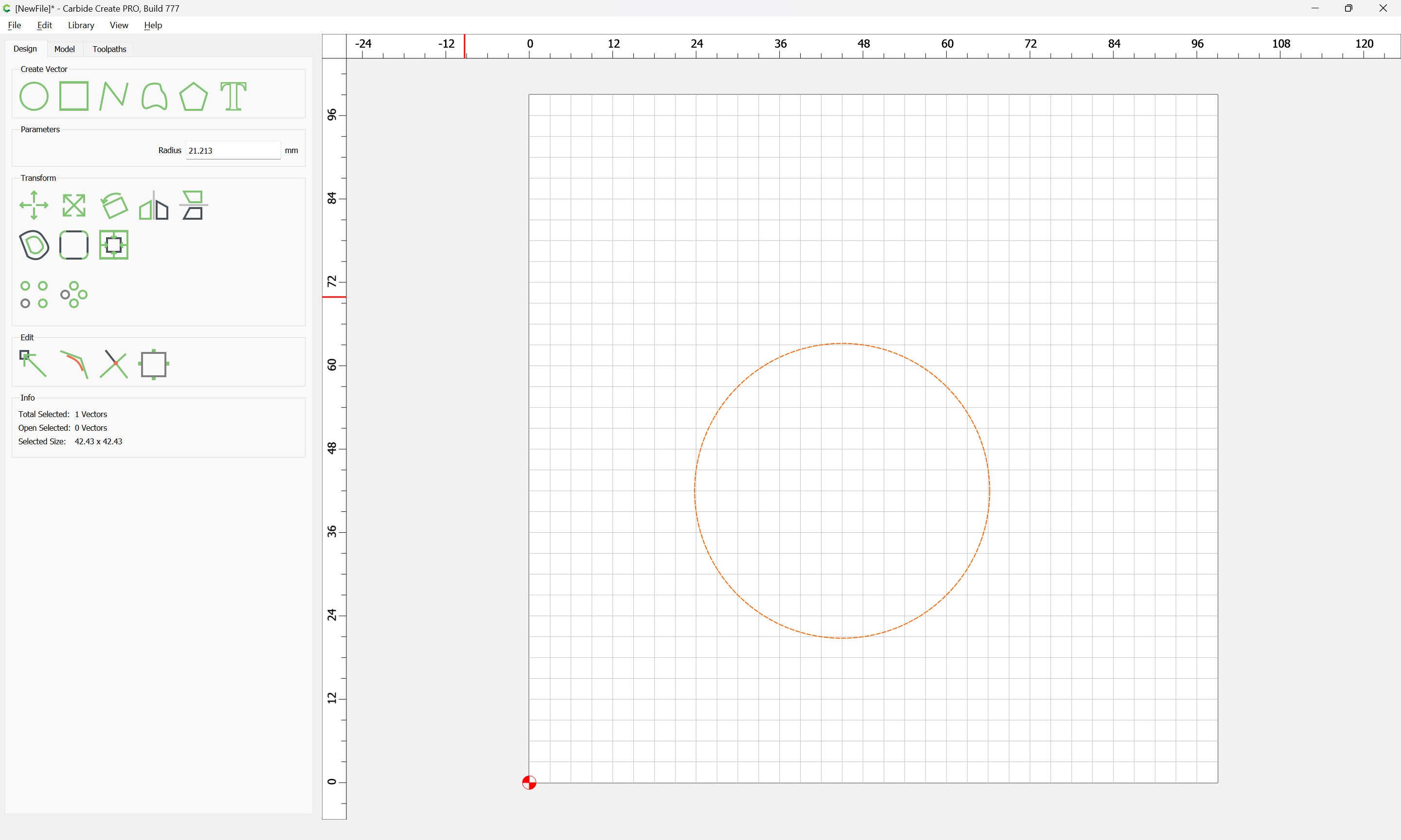
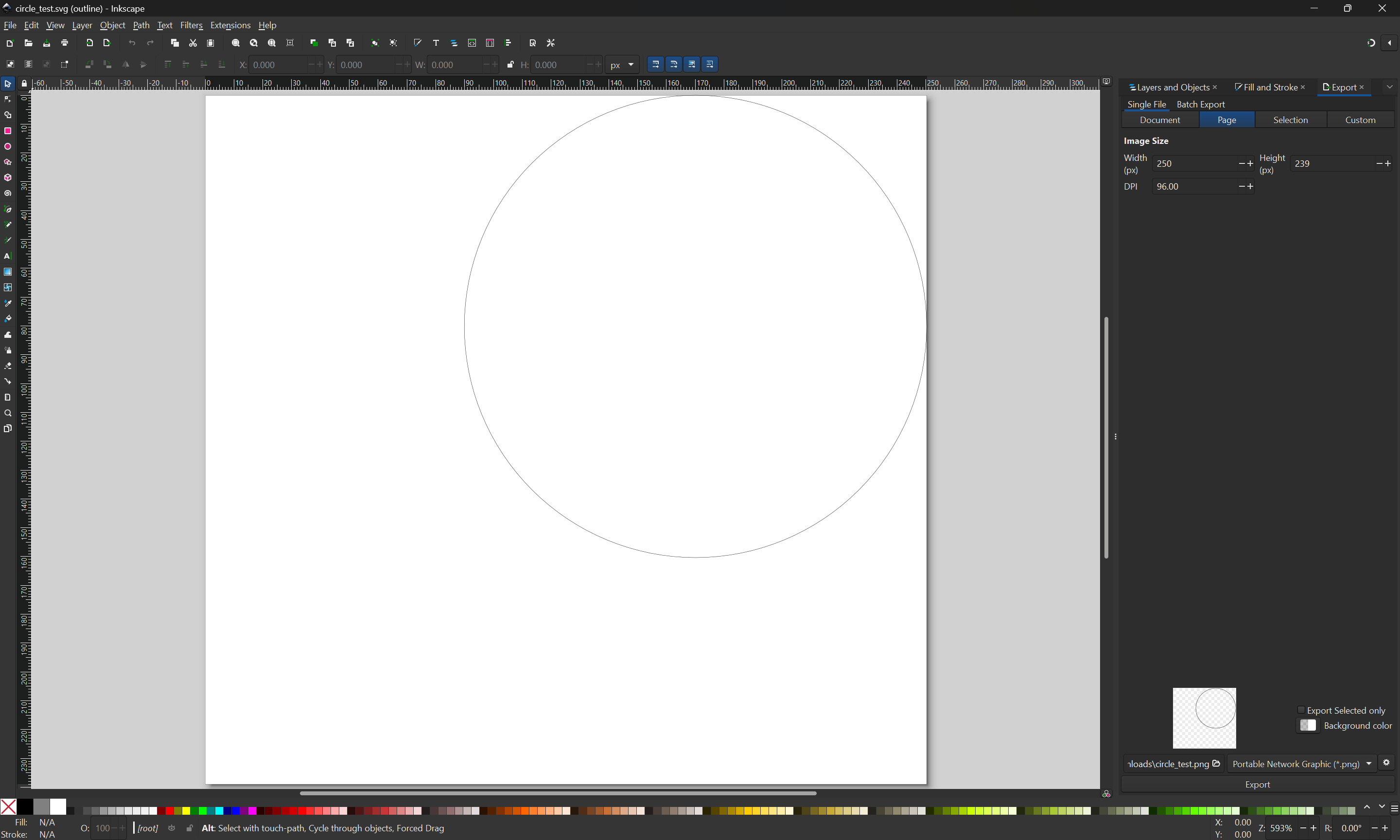
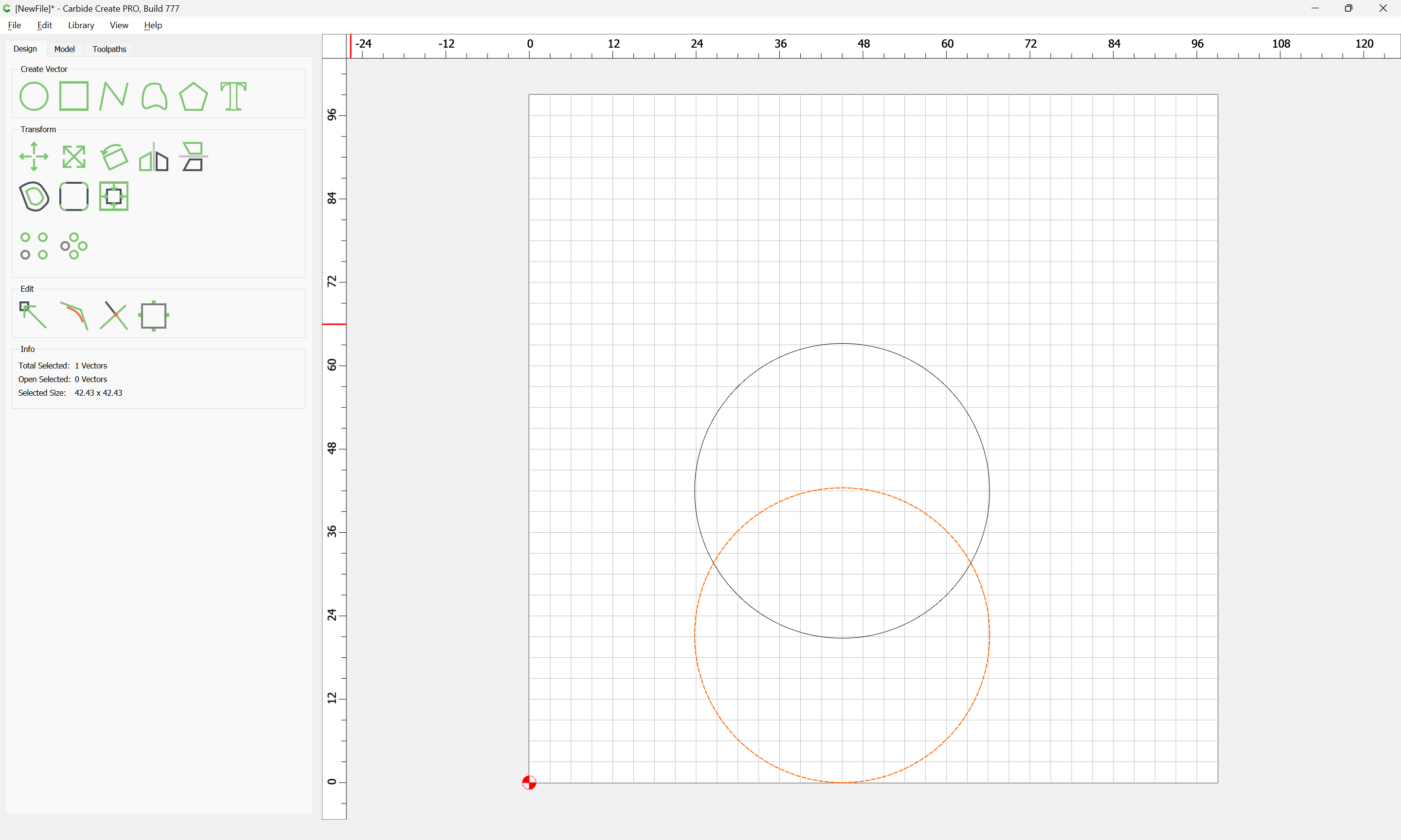
Opening the SVG in a 3rd party tool confirms that it is displace above and to the right of the lower left corner (which Carbide Create uses as origin):
We see that the left–right positioning is maintained, but the top–bottom is discarded so that the object has its origin along Y at 0.
The most straight-forward way to address this is to ensure that the lowest object along the Y-axis has its origin at Y 0 and that it has zero stroke assigned to it (if using a program which includes the stroke in the dimensions/positioning information) and the most straight-forward way to do that is to include a filled (but not stroked) object as a background.
Because CC expects an image resolution of 96dpi for SVG/vector images. SVG/Vector images are mathematical constructs that are resolution independent. Carbide 3D opted to pin the resolution of all vector objects to 96dpi.
Draw a 2 inch square in AD and export it as a 96dpi SVG file. When you open the image in CC and when you cut it, the dimensions will be exactly 2 inches. You can make the line width anything you choose and the internal dimensions of your 2 inch box will be 2 inches exactly.
I did the same test with my apps with a rectangle displaced both x and y. Results:
CC ——> Affinity Designer (AD), same displacement
AD ——> CC, y axis displacement ignored, same as your test
AD ——> Graphic, y axis not ignored
CC ——> Graphic, same displacement
Graphic ——> CC, y axis ignored
Graphic ——> A, y axis not ignored
It’s evident to me this is an “issue” with CC, Occam’s razor. CC seems to export the y axis offset fine but somehow ignores it on import. By “issue” I mean more of a quirk since it doesn’t seem to impede the functionality.
As far as managing my registration frame I’ve settled on using a zero width frame then selecting it in the layer manager. This has the added advantage that I can lock it since I don’t need to drag a selection box around it.