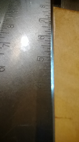
Wanting to tram and watching videos and reading as Mike suggested, I figure that squaring the machine should be the first step. I’ve gotten a dial indicator though I’m not happy in it’s precision and all the squares I’ve looked at in the big box stores aren’t square to each other. So without a machinist’s square, how do I square it with measuring. I checked Edward Ford’s 3D model for dimensions and now I know what square is suppose to measure. Except there is only one dimension that turns out to be a whole number, unfortunate. But I think that it would help people assembling a new system if they knew what the actual dimensions were suppose to be. If Carbide3D doesn’t agree than they should sound out, I’m only publishing the dimensions from their model and only trying to give a helping hand. Now I can measure for square and know what to shoot for for all components.
I’m starting my squaring/tramming/surfacing journey as well. I finally added some threaded inserts to my stock XXL wasteboard yesterday so I can bolt down additional MDF sheets for surfacing.
I started to monkey around with measuring and using a tape measure across corners I’m easily with .032" corner-to-corner.
I was also curious about the influence of initial Y-gantry position when pushed by “hand out-of-square” followed with a power up operation and homing/jogging vs squaring the gantry position and then homing/jogging. I still have more tests/measurements to make, but I do want to share some initial findings on squareness and travel.
I squared the Y-gantry to the rear frame by hand, then homed and measured the gap between gantry and frame. They were within .025", which is consistent with my less accurate tape measure method. Upon rapid positioning to the front of the machine I maintained the same .025" frame differential.
I think that’s consistent across the full travel extents of the machine and what I derived from my initial squaring determination. More scrutinizing to follow as I continue this endeavor.
I really didnt have to try too hard with mine.
I just got everything LOOSELY assembled.
Squared the frame with a Framing square (Bigger is better).
Tightened all the bottom half.
Then pulled the X member all the way to the front, tighened the front.
Pushed it all the way to the back, then tightened it.
Thats it.
If it ever gets out of square (the x member), When off, just pull it SLOWLY, all the way to the front again, or back, but actually the v wheels keep it from cantering too easy. Pretty much self squaring while it homes.
You still have to check if it’s rocked back and forth, but I was just careful to keep the beam lined up square with the bracket, and have noticed no scalloping.
I’ve never even put a dial indicator on mine, and everything assembled fine.
Mainly just start square, and tighten from the bottom up.
Of course every machine is a little bit different 
Looking at these dimensions from a far ways away, I wonder why they are so far from a nominal length. But realizing that the final working area of the Shapeoko 3 is 16" x 16" than it is because that is the geometry required to result in whole numbers (16x16). This is an amazing design and I am quite pleased with it. So it is just up to me how accurate I can square the frame and it is after all “a kit”.
You can tell a lot of thought went into it.
And of course how the parts were made and treated on the way to your house, LOL.
Seriously, it’s a great product IMO ![]()
I think the best way to do so is iteratively. You can get a long way without a precision square at the others here have pointed out. A big framing square and some clamps can get you a almost there. That -might- be good enough for what you’re trying to do.
If not, move on to the next level with an indicator… A dial indicator is pretty much a dial indicator, wherever it comes from. What you’re looking for is change as you sweep across the surface, not necessarily the actual measurement. Don’t go here until you are pretty sure that the simpler methods aren’t getting you where you need to be.
Is there a way to test for square w/ a DI?
Had to google it Mike, that’s the way I’m taking," repeatatively" measure, adjust, measure, adjust. Your word sounds better. Thanks
When I do he Z axis I’m to run it up and down with the dial indicator mounted sideways against the side of something square and watch for movement of the dial. That should be the last step before I measure and adjust again.
Yes, with some limitations of what you can reference against each other.
Here’s an easy-ish place to start:
Mount the a mag base in place of the router on the Z carriage. Put the DI in contact with the spoil board, and sweep (via gcode/jog) from one end of the X axis to the other. If you see things change, you can read off the indicator roughly how much off you are with respect to the gantry. You can do the same for Y. If you have a reasonably square (this is harder that it seems) block, AND you already have the base board square with respect to Z carriage, you can then sweep up and down against that block and measure how out of square -that- axis is. Telling how far out you are is the easy part. It can be very unclear where the error is actually coming from, and what needs to move to make it better. That almost always moves something else a little…which makes the cycle start over again.
This is a ready source of frustration if you don’t already have enough!
The biggest headache, doing this, is you’re testing the machine against it’s self.
For instance, the waste board needs surfaced first, before you can put a square on it, and be accurate in the thousands…
The machine needs to be squarely assembled before surfacing, etc.
That being said, it was precisely made, and that makes all the difference in assembling an accurate machine.
Yeah, I have plenty of frustration, but at least the Shapeoko WILL obey me and I will achieve perfection if that is the last thing I ever do. Thnaks to all, I hope others have gained from this also.
Cut a square pattern into a piece of plastic and measure the diagonals with accurate calipers or check them with a precision square. That’s the easiest way to check what you have. Getting it closer is another story.
I noticed that the back of my dial indicator is screwed on. I will simply nut a bolt through the mounting hole and engage the bolt into the collet. When I need a 90 degree reading than I will unscrew the back, rotate 90 degrees and rescrew it . A simple approach to a complicated situation. How bout that ?
It worked out just fine, my new problem is that of all the squares I have, framing, 24" carpenter, compound and an old 2" machinist’s square, the only one that is anywhere close is the 2" one. All the others are so far out in machinist’s speach that they are useless for squaring. My table saw is square but I squared it to the now known unsquare carpenter square. Like you said [quote=“mikep, post:9, topic:5480”]
This is a ready source of frustration if you don’t already have enough!
[/quote]
I think the real culprit is the spindle rotates just a slight amount causing the D I to move resulting in non repeatable measurements and locking the spindle with the makita is the problem. Holding the button in still allows slight rotational movement so locking it down so the D I is at 90 degrees is the difficulty. I’m getting anywhere from .08 to .13 in vertical on the Z axis.
Had to vent a little of the frustration, after a bit I’ll try again securing the spindle with tape, I have a framing square clamped in verticle and the carpenter square against the face of the framing square because the edge of the framing square is so far out of flat. Like you said Mike, than maybe the carpenter square will get me a close and repeatable reading. I’ve checked the v wheels for tightness as that is such a culprit that is so often overlooked. [quote=“mikep, post:9, topic:5480”]
a reasonably square (this is harder that it seems) block
[/quote]
I’ll cut and sand a piece of 3/4 ply until it is square and use that, I’ll verify it square with the caliper using the 3 4 5 rule . Than I’ll report my success .
Another method to use to square the bed is use a drafting triangle and four 5mm or 1/4" shelf pins. Drill two holes inline on y axis and two holes inline on x axis. Insert shelf pins in holes. Check square between your pins and drafting triangle. Use a feeler gauge to determine which way the machine needs to be square. Adjust diagonal to correct for 50% of error. Drill new set of holes, repeat.
Just like any new machine, it takes a little while to set it up correctly. Patience.
I built a square.
See how far out my new carpenter square is, Normal Harbor Freight quality.
Only took 3 attempts to sand it square and verify with calipers.
Now for the spindle:
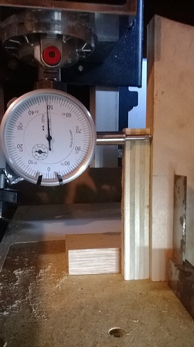
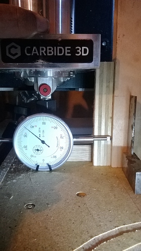
looks like 49 at the top and 35 at the bottom. Finally I know my spindle is not verticle. Now I know I need to square the whole machine from the start and work work work my way to the Z axis . Step by step we slowly approach and with a …
Thanks to everyone, I made my square, secured it square and than added a guide strip to keep the D I pointer from wandering down the edge. Success, not in calibrating yet just in knowing I need to .
I drew the z axis measurements in sketchup and the Z axis is 0.3 degrees off of vertical. Will I mess with it? Time will tell after I built the new solid base and really square up the machine with a true square and the D I and calibrate belts.
Yeah sorry I didn’t pick-up on the point that the OP didn’t have a reliable square.
Drafting triangles are typically very accurate. And quite easy to prove, you just get a pair and place them leg to leg with a straight-edge at the bottom, and there should be no gaps between the two legs. I purchased mine at the local university bookstore. They also have them at Office Depot BUT, try to get ones that don’t have beveled edges, they’re great for pencil lines but a pain for checking for square.
Craig’s method is good. But before you even start drilling for shelf pins, you can use 1-1/2" thick sheet goods (two pieces of 3/4" is fine) to extend the gantry extrusion towards the table, then check that against the left or right (or both, one at a time) Y-axis extrusions. Do this with the motors on and locked, so things don’t start shifting on you.
To square my router/spindle, I used a 6" long combination square and checked the aluminum body of the router to the table. You can also do this with the plastic triangles.
FWIW, you can get inexpensive combination squares and “adjust” them. My first combination square was a Starrett and it proved against a couple of plastic triangles, and passed the flip test (don’t do a pencil line, use another straight edge places against the rule, pencil lines are too thick).
Once I had the Starrett, I purchased a cheapie 6" combination square that wasn’t (square). But I used a diamond needle file to adjust one of the registration points on the head until it matched the Starrett perfectly. I did most of the adjusting at a softball game in which my daughter was participating. I was the guy sitting in the stands with a file, a combination square, and a triangle, sometimes filing, sometimes watching the game. It was actually quite enjoyable, I just snuck up on it.
The important thing is that the combination square has to start with a good, straight rule. Check that first, then move onto tuning it.
My 6" unit I got on eBay looks just like this one:
http://www.ebay.com/itm/3-PIECE-6-INCH-COMBINATION-SQUARE-SET-4901-0313-/351937366418?hash=item51f11a0992:g:QuUAAOSw-0xYWHZ2
But I paid a lot less than $25 for it (IIRC, about $12 or $13 shipped).
I started with a Dewalt router and then tried the Makita. I really wanted to like the Makita, as the lower RPM range and the two-wrench bit changes are appealing to me. BUT, I found that I get deflection of my bits on the Makita. Cutting a square (for instance) would result in what appeared to be a truncated pyramid. The error was slight, but consistent around all four edges of the square.
I chased my tail on that for a while and then put the Dewalt back into the unit, cut a square, and low and behold near perfection.
I don’t know if my Makita was an anomaly or if the collet design contributes. I did find a post from someone else (maybe not even here) that complained of the same issue on the Makita, and he theorized that the collet of the Makita really clamps hard at the front but not the back of the collet, whereas the pressure on the Dewalt is more even. I do not know if this is the case, or not.
Hopefully I haven’t gone too far off on tangents.
As others have said, you need to start with a flat and square baseboard before attempting any real Z adjustment.
@Tshulthise’s recommendation of using a cut square with a small precision square is a great one (if you have a decent square to reference). It’s easy and fast, and low frustration factor to see what direction things need to move.
In my not-always-great opinion, a 6 inch machinist square is one of the very first “CNC” tools to buy (#1 is a DECENT set of calipers, #2 is the square). With it a lot of things are made a lot easier. I have one of these (https://www.amazon.com/150mm-inch-Engineers-Square-Wright/dp/B00JPGD61K/ref=pd_bxgy_469_2?_encoding=UTF8&pd_rd_i=B00JPGD61K&pd_rd_r=DM2H9GGQBQRADKSG4YBS&pd_rd_w=9taoD&pd_rd_wg=W7Uso&psc=1&refRID=DM2H9GGQBQRADKSG4YBS). There are many options, many cheaper and probably just as good.
Mounting the dial indicator in the spindle isn’t going to help much - the spindle can rotate and it just won’t work out. A mag base (even a super cheap one) makes it easy though - take the spindle out of the mount, and put the mag base on the moving Z plate. This will work for measuring belt stretch and travel in all axis.
Thanks Mike and Phil, I’ll be transgressing along this route throughout this next week, too many other real frustrations in the way. But I will adapt and overcome. I bought some engineered boards that are machinable but don’t react to humidity (30 $'s) “miratec” at home depot
, they will be the new base and off I’ll go squaring and aligning and calibrating from a level surface. Thanks so much for all the encouragement. On my wooden square I glued an edge to keep the D I point on a straight line and that keep me on a vertical movement, I also didn’t worry about the middle just the top and bottom measurements. Anyway now I know where I am and where I must go. The path to enlightenment is a road of dark passages. “Follow the yellow brick road…”
Looks like it, home depot miratec 6" (5 1/2") x 8’ board 3/4" thick $10.?? The caliper varied very little down it’s length can’t remember how much but was enough less than even the star board they had that I bought that instead of the star board.
checked your link, this is the one
https://www.miratectrim.com/miratec-prefinished-trim
home depot didn’t have the smooth select


