What is the best route to flip something over and car on the opposite side?

If he’s very careful to make sure the tool goes through the stock but doesn’t hit the inserts, I suppose they could be machined right over the inserts. Then he just threads in his locators through the holes. compressed air to get all the dust out??

If you didn’t have the inserts, you could program the hole path to drill the holes through the stock & into the table or spoilboard, creating both the hole & the locator hole at the same time.

I’ve found the following to give me decent precision and reasonably low mistake rates.

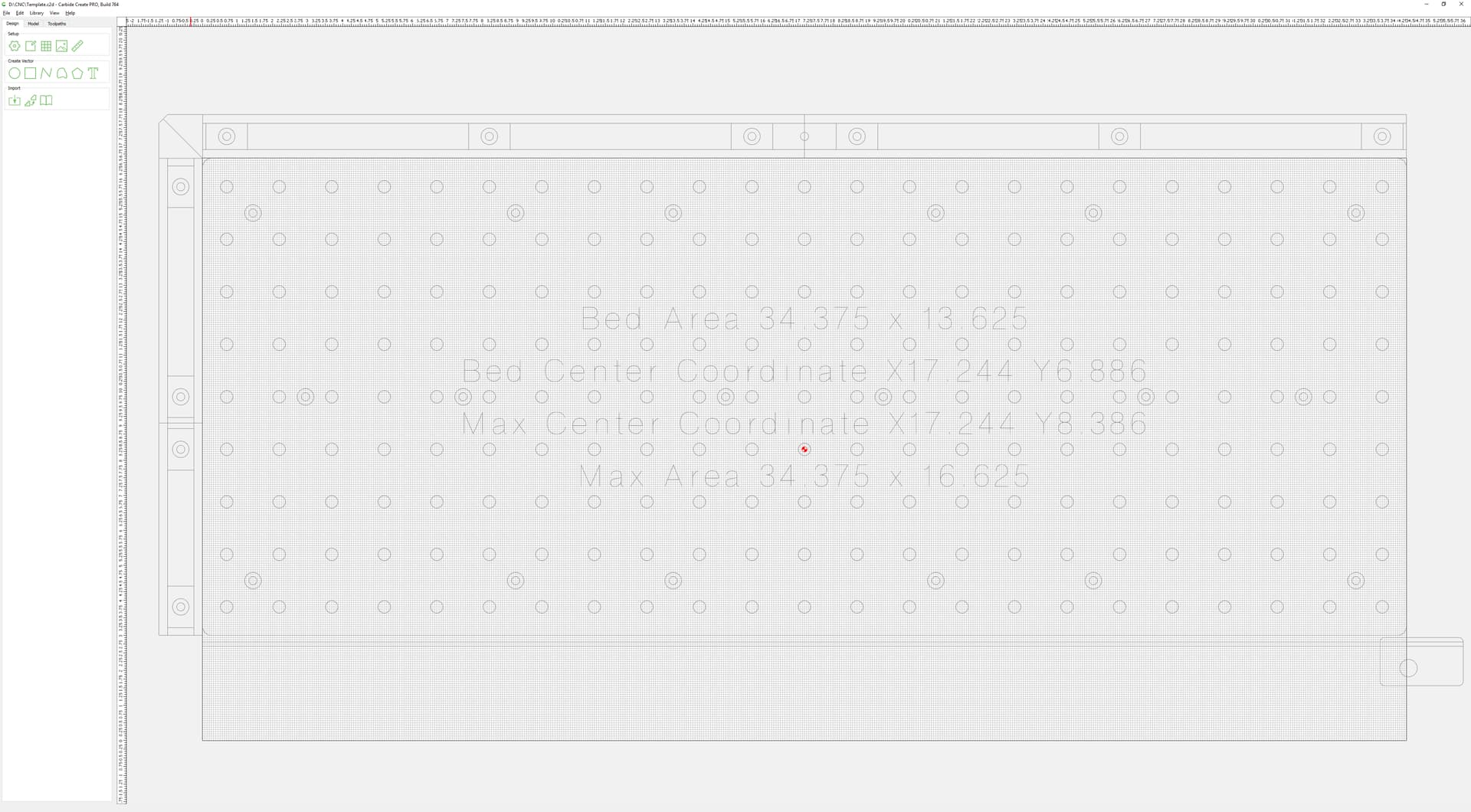
Bolt down a temporary fixture board, surface it flat and machine the front and left sides square and straight.

To get a really good repeatable zero I put a little CA glue in the sides of the MDF at the front left corner and re-machine the two edges, that gives a smooth and solid pair of faces to zero off.

Zeroed off that front left corner I then bore the pin holes I need for this project (you can re-use the fixture a few times before it’s too swiss cheese). I now have a repeatable zero and bored holes in known locations from that zero. If you can do these on a regular pitch, that makes re-use easier. I also like to put a bit of CA glue in these, set it with activator and then re-run the boring toolpath to get a good solid repeatable pin fit.

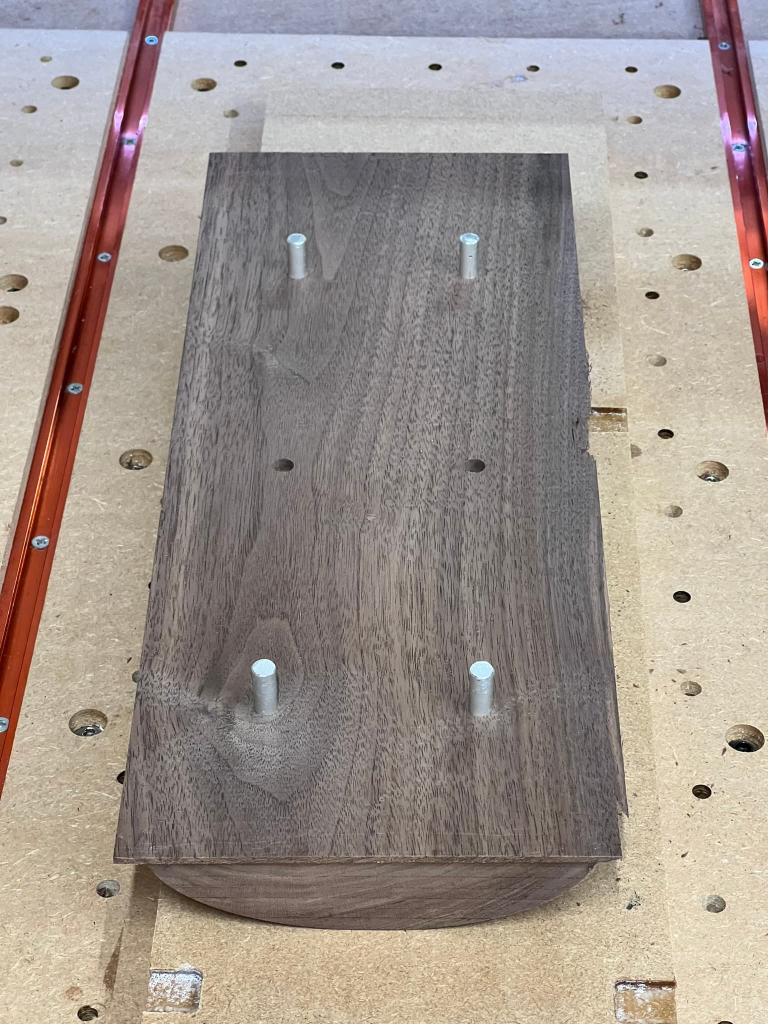
I then put the stock on top of the fixture, align it by eye and bore the matching holes for the locating pins and, if necessary, surface the stock. Now attach the stock to the fixture using the pins.

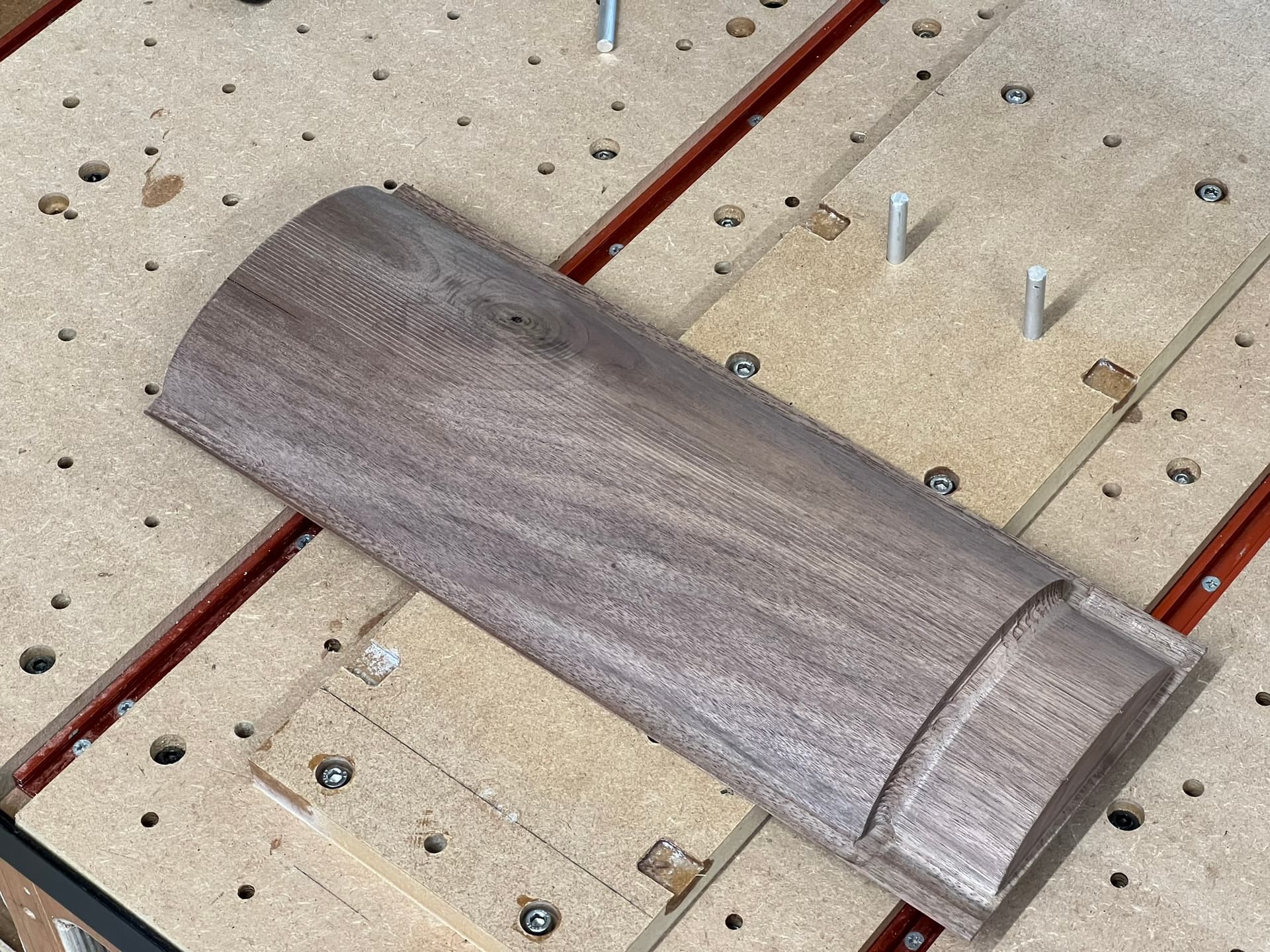
I then machine the first face, using the fixture as the Z=0 point, this way the stock just needs to be ‘thick enough’ and I can cut all the way through accurately.

Once that’s done, flip the workpiece in whichever direction you flipped it in CAM, put it on the pins and machine the other side, again, using the fixture as Z=0 and the same X=0, Y=0 off the front left corner.

You can keep doing this for many parts over power cycles by just re-zero-ing off the fixture, you can even put an old fixture back on the machine by running up the side with a dial indicator in the collet (best done at 0 RPM).

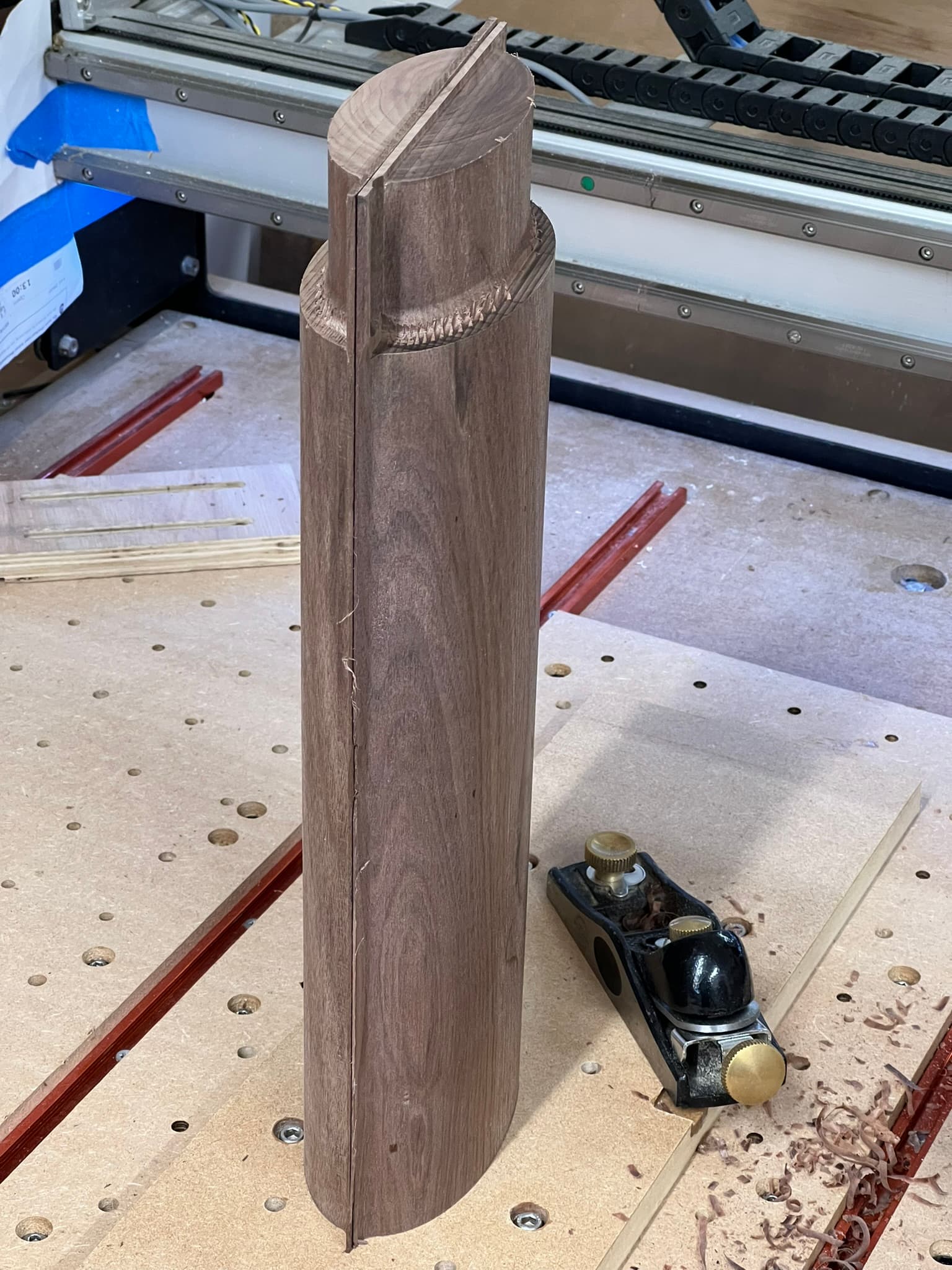
In this particular case, the two ‘sides’ were two separate workpieces which were to be glued together to make a single ellipsoid profile table leg and top through mortise.

4 Likes

whoops, guess I left out an important detail. I don’t move the machines zero to the center of the stock, I move the stock to the center of my machine. Sorry for the confusion, take a look at the attached Carbide Create file. I will zero my machine to X -17.244, Y -8.386 (the true center of my work area).

I then take my (close enough) measured center of my material and move it until that marked dot on the material is under the bit which is located at X -17.244, Y -8.386. That way I know any hole I drill lines up with the threaded inserts below.

Template.c2d (516 KB)

But all of that isn’t actually required for flip machining, I could have reset my X and Y zeros after drilling the holes and finding the center between those holes. Or maybe even use the machine to mark the center (between the holes) when it is drilling the holes.

So sorry for all the confusion, it appears my attempt to help may have done more harm than good.

2 Likes

No harm at all. Good clarification though. I have not been leveraging the machine coordinates or rapid position locations much but no see there are multiple good use cases.

I like this approach although I don’t have the threaded inserts. Maybe I could make a supplementary spoil board that would have them and some runners on the bottom to precisely align it in the T tracks.

I have been thinking about re-doing the fence I use for tiling and adding runners on the bottom for that same reason. It would allow me to more easily remove and replace that fence. Probably best to make it extra wide so that it can be cut along Y for fine adjustments as needed multiple times before tossing.

Good lord I’m gona pop from all this info! I think this is what they mean when they say you opened a can of worms.
I’ll reread and then re-reread this post again then I’ll go play with my machine!

If I have a large sign with an odd shape, I drill a 1/16 through hole in my exact centre. When programming the piece on the computer every design I use the centre as well as a straight edge usually I have the machine carve a straight line into my spoil board. It’s usually fool proof if I’m using both sides. When you flip the piece I set the 1/16” bit and move the router till it sets right into the hole and square to the straight line on the spoil board that’s about exact as I can make it. Just remember to orientate the program image accordingly. Also if you are adding something to a piece. Try placing the datum point in the exact centre of an image then place that centre point any where on the surface of the piece. The cnc should cut exactly from that centre point just remember to square the piece on the spoil board.

4 Likes

@Pan You don’t say what CAD/CAM software you are using, but you will find a couple of excellent vidoes on Mark Lindsay CNC on youtube that cover an excellent method for doing double-sided jobs in Vectric VCarve. It will work on any shape material and is fool proof - as much as any method can be. The method can be used with pretty much any CAD/CAM program that can handle double-sided projects.

2 Likes

This topic was automatically closed after 30 days. New replies are no longer allowed.