Hello everyone, I’m trying to figure out where to start and learning to flip a piece over to carve on the opposite side?
For small pieces I just use a square on the board to “register” the piece. I make sure the design is centered on each side mirror one side either up/down or left/right. Just remember to flip the physical piece the same way you flipped the design in the software.
All the ornaments I posted in the “What did you cut” thread were done that way and flipped left to right.
1 Like
Agreed. Use a “L” bracket on your CNC bed. This way you can just flip the piece over and align to the bracket. No need to reset zeros with this method. When drawing on CC, group the entire design and align to stock centre. Then you can just mirror the design left to right.
1 Like
Note that both Cullen & Derek’s method only works if the stock size in CC exactly matches the stock size on the machine. i.e. if flipping left->right, the X size has to be an exact match if you need things from one side to line up with the other side.
Strategy matters! If you cut away your outside border on the first side, you have nothing left to align with on the flip side. Cut any feature that goes through the part on the 2nd setup. Only cut on the first setup what you can’t get from the other side. Try not to cut the same feature from both sides.
On dimensionally critical parts, I use the same “J” corner for all setups. So if I’m flipping left->right, and my front/left/top corner is my zero for the first setup, then my front/right/bottom corner (The same physical corner) is the zero for the second setup.
5 Likes
Good point. Yes, in my cases I have measured the stock and represented it accurately in CC and I save the cutouts for the final side.
Although. I did a spoon this way as well and cut the contour halfway on the first side and then finished from the other so it worked fine.
Thank you so much I’m off to try some of these!
I’ve found several ways to screw up, so let me tell you about my mistakes.
- If you flip it the wrong direction, you feel stupid.
- If the actual size of your stock material doesn’t match your measurements things can get off. And getting your stocks actual size is MUCH harder than it sounds, because even with an accurate X and Y measurement that method is built on the assumption that your stock is perfectly square.
- If you base a two sided flip using a corner, any error gets multiplied (at least it was for me).
- If you base a two sided flip using the center, you still have to worry about rotational alignment but I seem to have better results (assuming I found the actual center). Best analogy I can think of is an old record, there’s a reason those had a single hole in the center.
- If I can start a job by creating (drilling) two reference holes, I can use those to “flip” and realign the stock. This produces the best results (for me). My wasteboard has threaded inserts every 1.5", so I will design a job to have flip-holes outside of the design area, that are multiples of 1.5" apart. My last “flip” job was making something that was 12x12, and I had the flip-holes 13.5 inches apart (both 1.5" outside my design area).
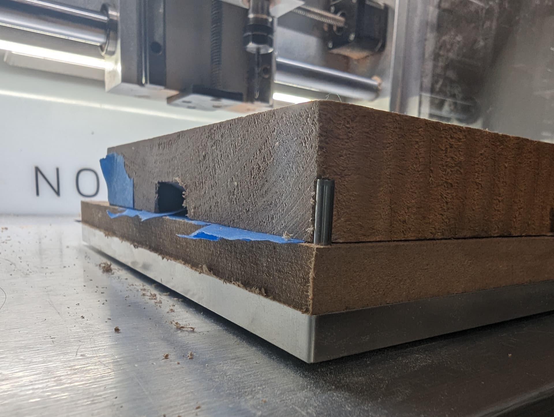
- Run a surfacing job on at least one side. Whatever thickness the material claims to be, it probably is not. While the surfacing step is running, make sure the bit at least skims the entire material area. Uneven surface can cause you to unknowingly carve side “A” deeper than side “B”, which may or may not be a big deal (depending on your design).
- I don’t know the percentage to tell you here, but if you are working with wood, the more “material” you remove from side “A” the more that material is going to warp-bend-stretch on you and your “flip” won’t be symmetrical.
7 Likes
Great info. I have not found the need for the registration holes yet and to be honest thinking about them scared me away from doing flips for a while.
I am sure so will encounter cases where I will need them though. Can you explain where you put them more? Maybe a sketch? And in the case you describe below where did you set zero? The center or the corner? Or is it somehow related to the pins. How do you know that you have the stock placed such that the registration holes align with you inserts? Do you just pull their location into your CC file?
This seems like it may take a little bit of practice!
Just don’t overthink it.
Try it on some scrap and learn from the mistakes.
Worst case is you have something that looks really nice in MDF and you wish you had used walnut.
Lmao thanks again team!
The image below is from my last two-sided job. The design is 12x12 and the material I used was roughly 16x13 and not square.
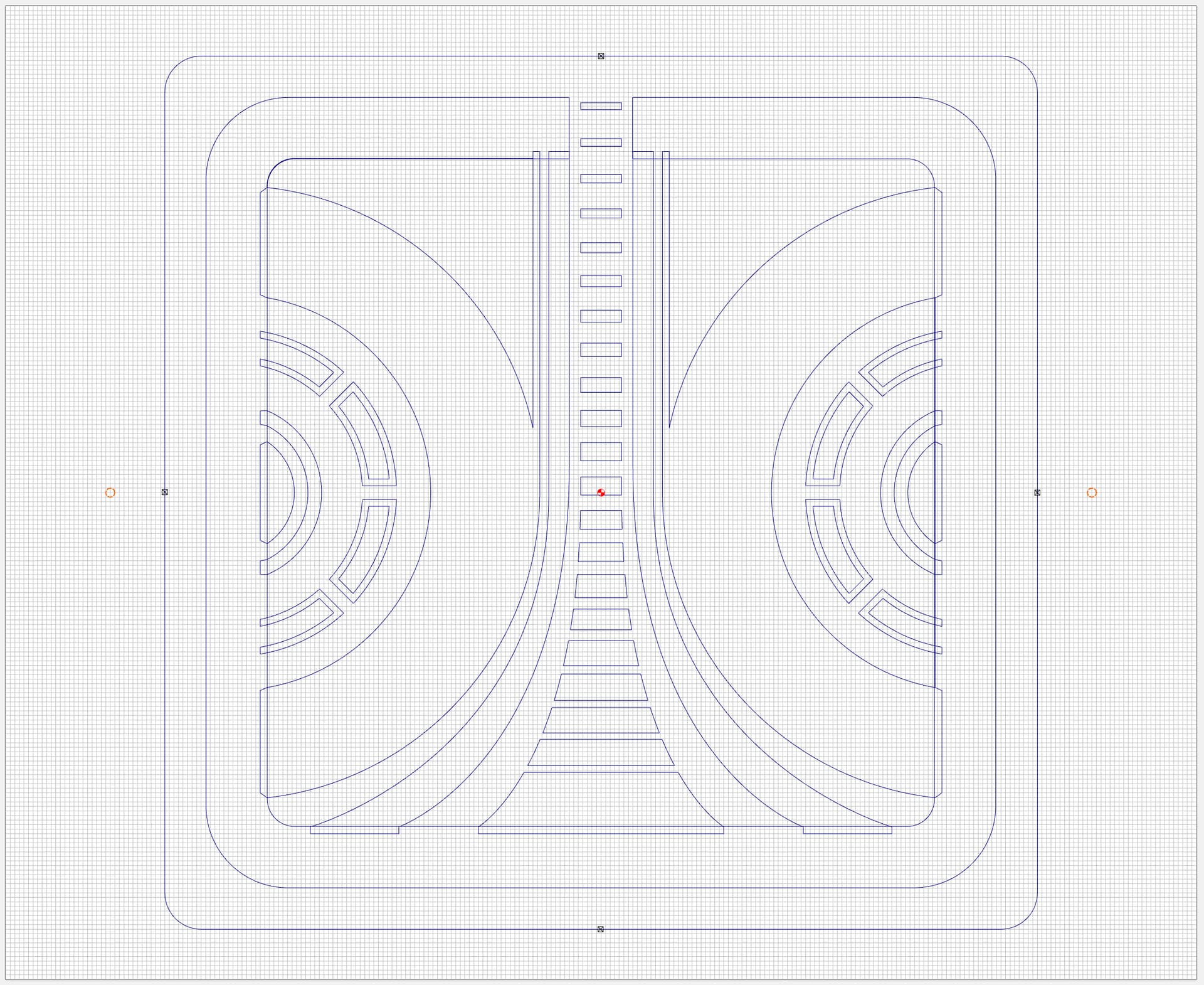
The red (selected) holes outside of the design are my flip-holes. They are 13.5 (center to center) apart from each other which lines up with my waste-board threaded inserts.
Step 1 is I drill out these holes, and it does not matter if I’m off center or my material isn’t perfectly square. At this point it’s just two holes 13.5 apart, the right size diameter for my threaded inserts. I then bolt the material down to my waste-board.
So even if my material was REALLY off (pretend the highlighted square below was the edge of my material)…
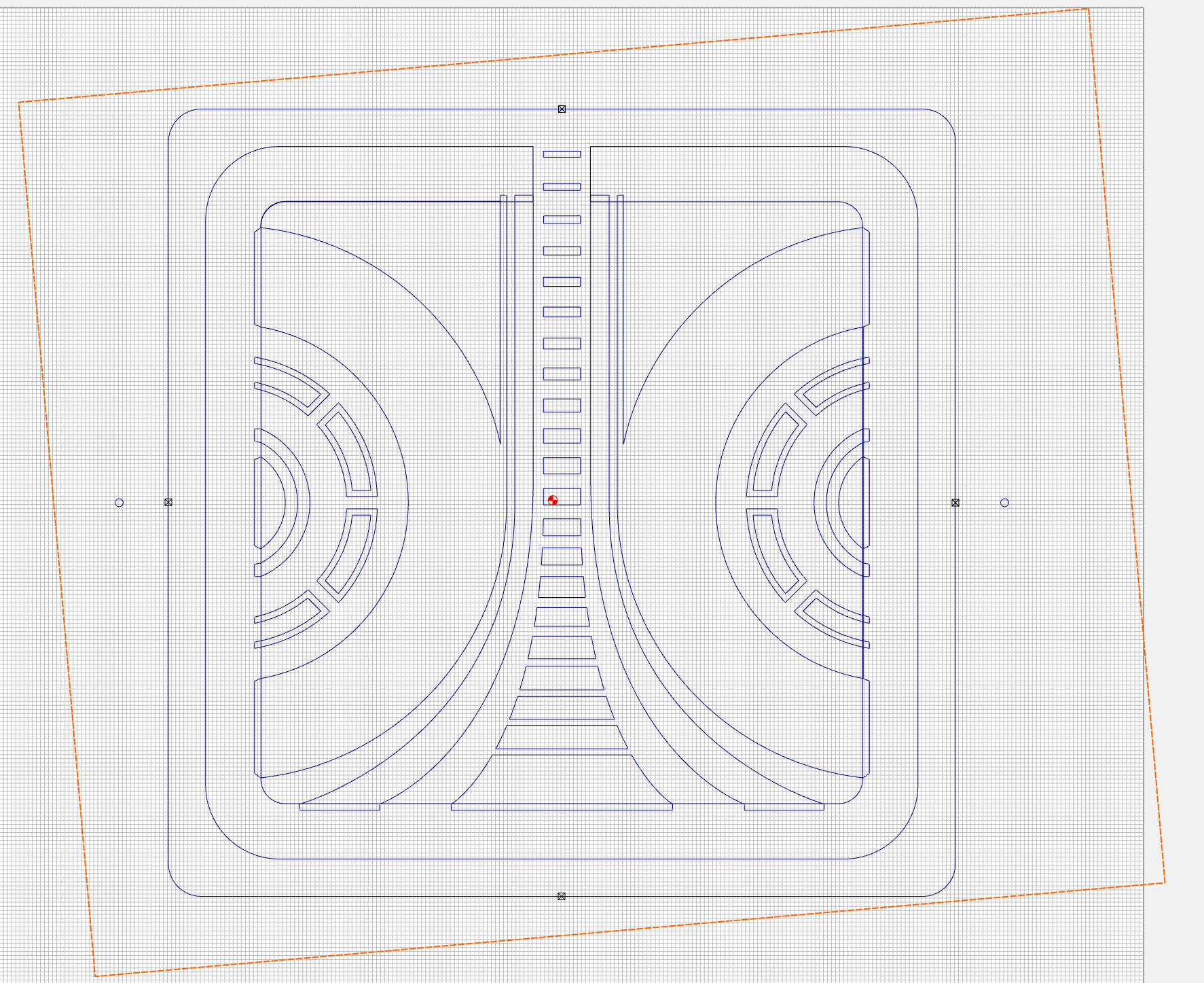
… when I flip it over, as long as I re-bolt into the same threaded inserts my design is still centered in reference to the two holes. I do NOT change my zero settings, I just run the job for the other side.
It’s basically the same concept as doing “tiling”, instead of moving the material you’ll be flipping it over.
4 Likes
So you bore the holes and then fasten for side 1 and then set zero I assume.
I set the zero before I made the flip-holes. 90% of the time my Z-zero is the top of my wasteboard (not top of stock). And almost as often I X&Y zero to the center of the stock.
If I zeroed after drilling the holes I would have run the risk of the holes not being equal distance from the center, so the flip might have been off (depending on which axis I flipped on).
Wow, a lot of info here think I need my hands on my machine to understand it all I’ll be working with this for the next few days, so thank you all so much!
Ok. I guess I just don’t understand how you ensure that your holes perfectly line up with the threaded inserts then.
I’m likely under-thinking this but I have always used either: Homemade flip-jigs or multiple 0,0,0 homes for multiple soft-jaw set ups (G54, G51, G120, etc.). Manually entering in coordinates and correcting for errors when moving the workpiece by altering the generated G-Code. Seems like the CC community has some great ideas though, much easier probably!
1 Like
My guess would be they are designed that way. Machine the holes with your machine and make them multiples of 1.5" apart. He said the threaded inserts were on 1.5" centers.
Then position the part using the threaded inserts, set your zero & go Hawaiian ![]()
1 Like
But this is what he wrote.