In my quest to understand the differences in Gcode between milling and laser marking I Googled this “What is the gcode difference between milling and laser marking”
The primary G-code difference between milling and laser marking lies in power control (S-codes), tool control (M-codes), and the role of the Z-axis. Laser marking G-code acts as a 2D drawing tool using power-scaling commands, whereas milling G-code controls 3D material removal through spindle speed and depth-of-cut commands.
Here is the breakdown of G-code differences:
Laser Marking G-code
Laser G-code is often characterized by 2D movement (X/Y) with varying laser power (S) and laser-on commands (M3/M4).
Laser Power (S-Code): The S-parameter regulates laser power (e.g., S500 for 50% power, assuming a range of 0-1000).
Laser Control (M-Codes):
M3/M4: Turns the laser on. M4 is typically used for dynamic power control, adjusting power at corners to prevent burning.
M5: Turns the laser off.
Movement:G0 (Rapid) is used for positioning without marking. G1 (Linear) is used for marking at a specified feed rate (F) and power (S).
Z-Axis: Often ignored or set once at the start.
The Gcode differences seem trivial ( ignorance here). The one big question becomes the Z-Axis. Does anyone know if CM ignores the Z moves when the $32=1 and M4 is used ?
GRBL seems to support the Z axis movement.
Google response
Yes, GRBL supports Z-axis moves in laser mode (), allowing for manual, software-driven, or G-code-defined focus adjustments. While laser mode typically disables automatic spindle-related Z movements to optimize performance, it still processes G-code commands (e.g.,) for Z-axis moves during operations.
Key Aspects of Z-Axis in GRBL Laser Mode:
Focus Adjustments: You can use manual jogging to set the focal height before a job and in some cases during a job, though jogging during a run is not typically available in LightBurn for GRBL.
Automated Z Movements: You can use Z-axis movement for Z-leveling or to change focus over multiple passes.
Compatibility: Both LaserGRBL and LightBurn can handle Z-axis commands. In LightBurn, you must enable “Z-Axis” in device settings to control the Z height.
Potential Issues: If you find the Z-axis is moving when you don’t want it to, it is likely due to commands within your G-code file (e.g., end-of-job code) or specific software settings, rather than a restriction in laser mode itself.
If that is true, then a Milling operation ( like Contour or Pencil ) from a CAM app should work ?
Laughs, Comments ?
I’ve asked jtech about the focal distance of their lasers. I expect they would work but the chimney that goes down to the workpiece would likely need to be cut back for clearance.
Maybe it could be replaced with relatively long brushes to catch a good bit of the smoke
The question I’ve really got is regarding the focal distance (maybe the wrong vocab) of the laser and how it interacts with the total z height you’ve got to work with.
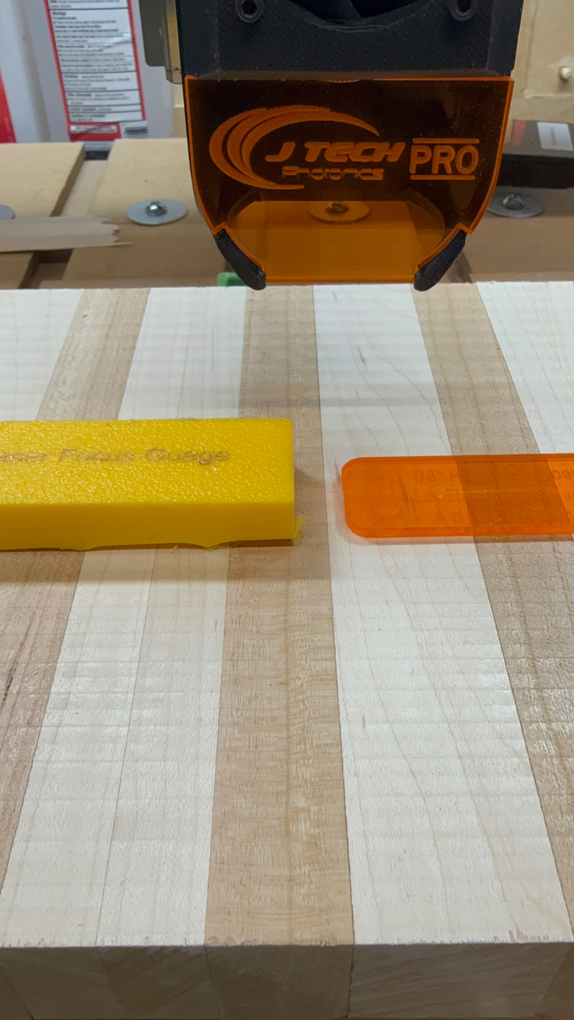
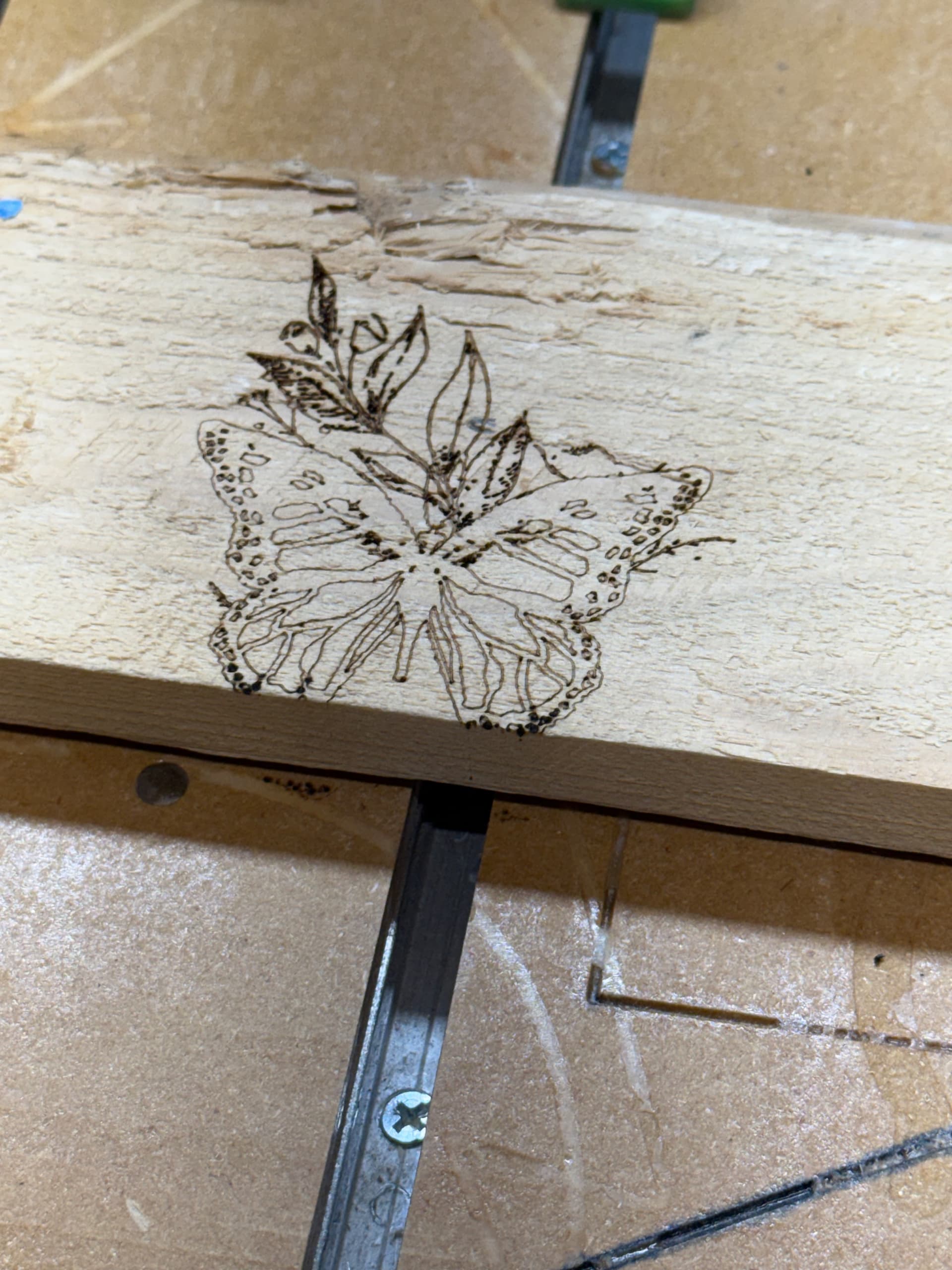
I had a laser marking project some time back where I needed to burn an image into a pocketed area. I got with JTech about changing the focal distance so I could clear the walls of the pocket with the laser during the burn. No problem at all. I went from the standard 1/8" gap to 1/2" by refocusing the screw in lens.
New setup tool on the left.
The toolpath was configured as one would do with a plain 2D object. I selected a MC Etcher, DOC = .001 and used a spindle speed to 8000 RPM. With a max spindle speed of 24000 rpm 8000 would give me roughly 33% laser power, (M3S8000). I just left my retract height alone for the test, it was set at only .050 anyway.
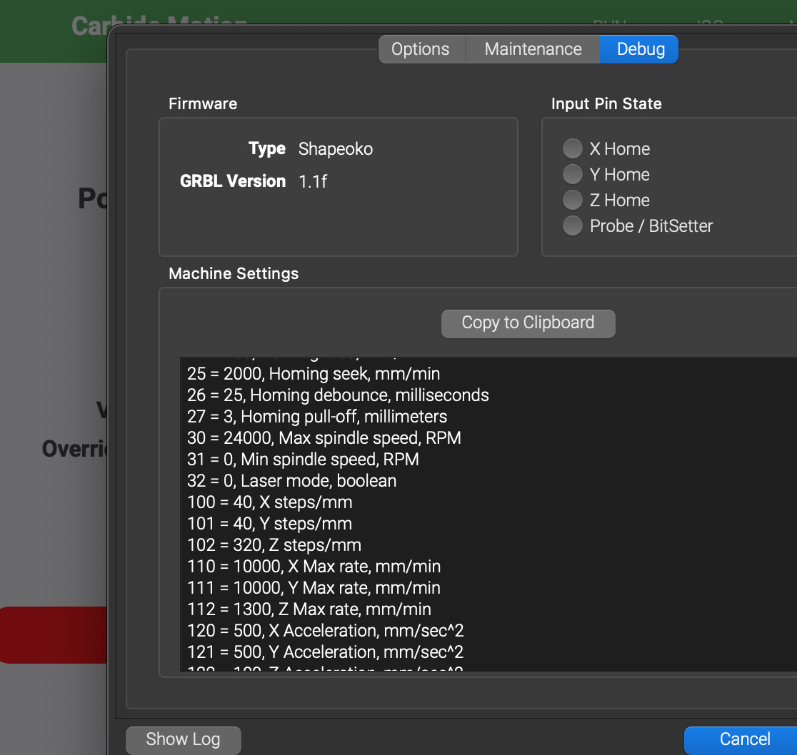
In Carbide Motion I sent $32=1 to put the Shapeoko controller in laser mode after setting zero’s. At that point I sent the .c2d to CM and unplugged the signal wire at the VFD from the Shapeoko.
I’m sure one could make the laser follow a contour tool path the same way one would set up a roughing and finishing path. The interesting part would be defining a single line to follow the elevation changes on a topo project.
I’m looking at getting a Laser and I had one question, what reference do you use to set the X/Y zero? I assume the laser, if so does it have a separate light you activate to assist in setting an exact starting point?
I create single line path in Fusion using the 3D contour path on meshes.
I have been “flattening” them using @Tod1d GREP script and etching those on acrylic.
The trick has been what Stepdown to use that doesn’t make a mess when too little.
I seems the only manual change I would have to make is changing the M3 to a M4.
I was considering adding a J-Tech but ended up getting a stand alone laser.
It has higher power, an enclosure, safety features, and a lot more capability for different types of projects.
If you don’t need the size of the CNC for your projects you may consider that.
I have mixed some CNC and laser activity on the same project which is doable if you align things properly. If you need an extreme level of precision on the alignment that may be challenging.