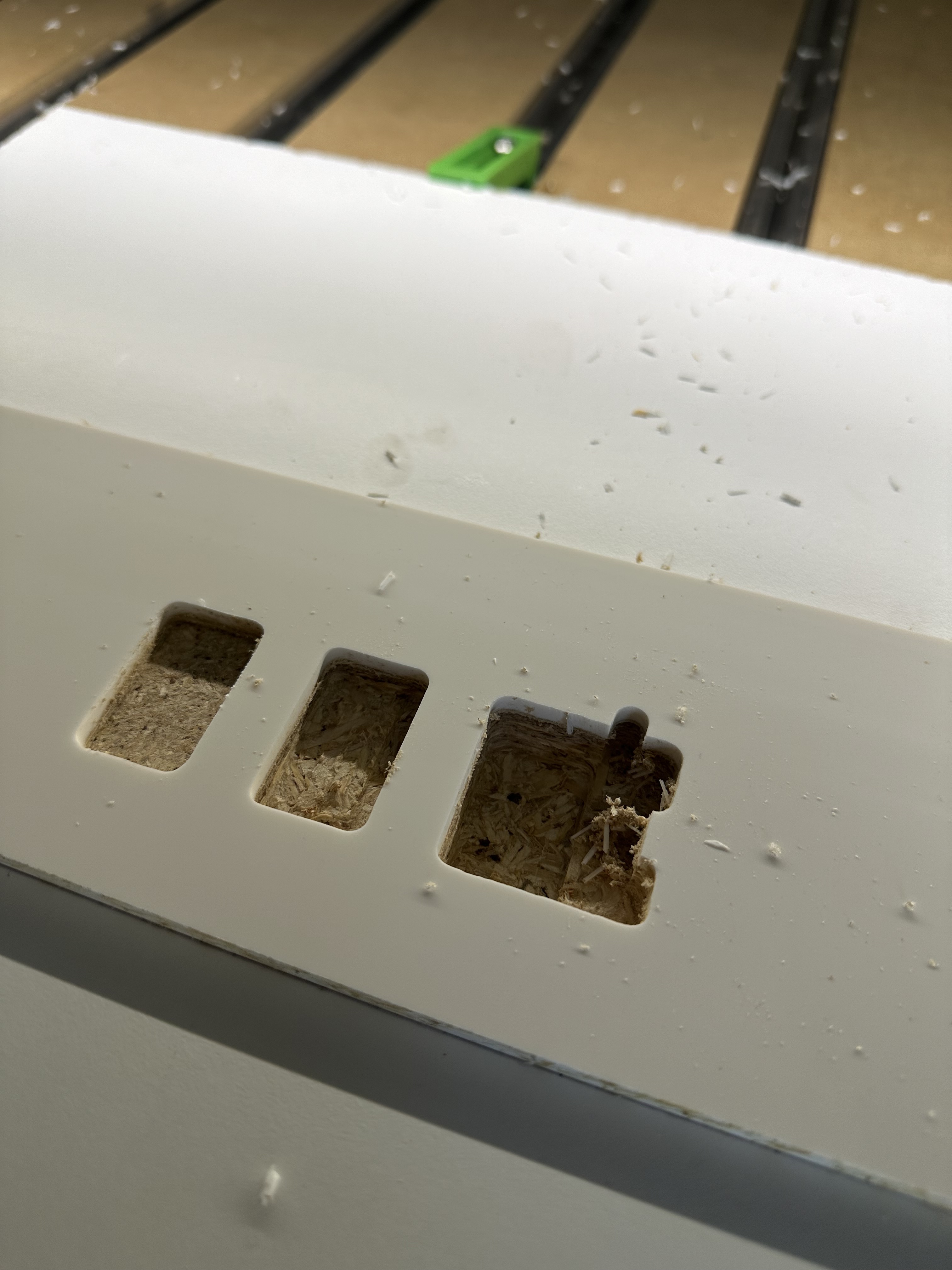
Is there something that I did wrong? The thickness of this acrylic is 4.61mm. It cut it correctly in the first hole, but then the next to it continually went deeper. I’m still practicing and trying to get my pocket holes right it’s the only problem I’ve been dealing with
Is your endmill working itself out of the collet?
Use wrenches to tighten them in and don’t rely on the button/lock on the router for tightening - needs to be more secure.
1 Like
It did the last two times but I also could it be because I didn’t use the right tool set preset ?
If your toolpaths are identical and the cuts are getting progressively deeper, assuming the machine and stock are square, it’s likely the endmill working out. I guess it could be something else, but it’s what I would check first.
1 Like
I completely agree given that I have been experiencing this recently.
Once you put the endmill in, use a sharpie to draw a line where it disappears into the collet nut. You can see then whether slipping is the issue.
2 Likes
What I also just noticed the but is not touching the bit setter.
If the bit is not touching the bitsetter then I would think that the probing would fail there.
Or, do you mean it isn’t going over to the bitsetter to do the length check? Does it do that after you set Z?
1 Like
The tightness of the collet is essential. Are you using a trim router or a spindle? The last cut (deepest) has very ragged edges and these suggest that the cutter was being held back in some way… rough cutter edges dragging the cutter downwards? Cutter loose in the collet and causing the rough edges. Are you using a single flute downcut cutter? What are the feeds and speeds? Do you have a copy of the .nc file or the CC file? (if you are not using CC Pro which I do not have so cannot view)
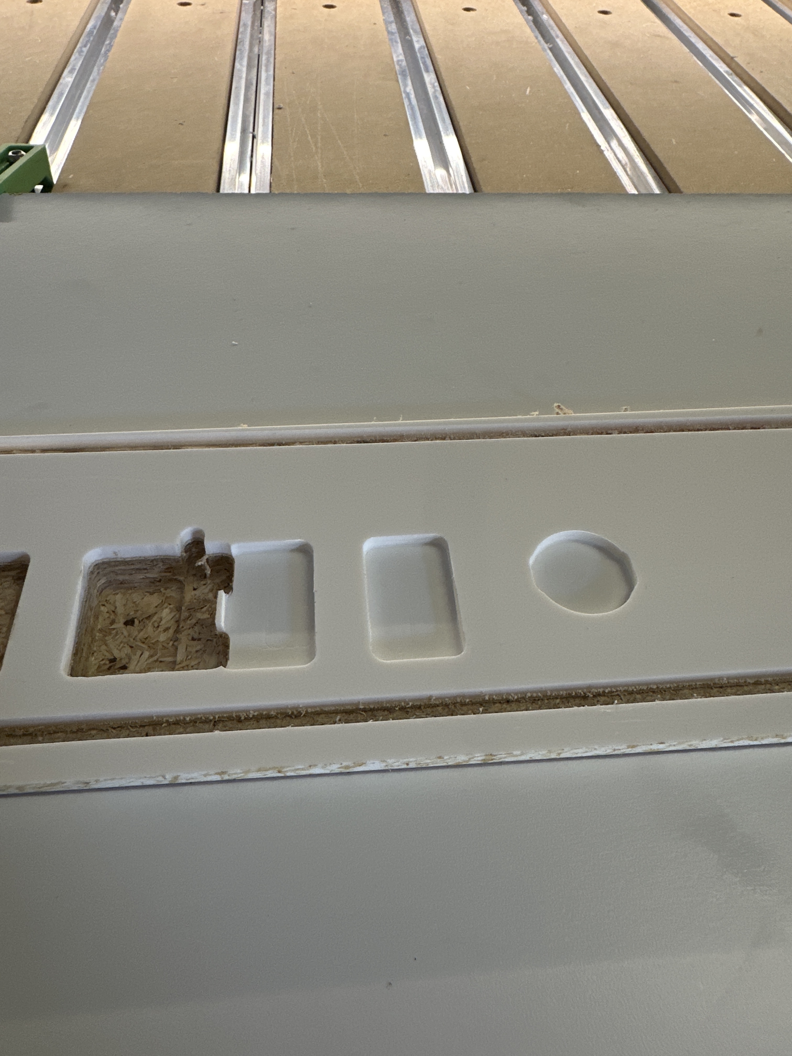
At first it going way off the bit sitter but I reinitialized and it worked but I changed the depth per pass to something lower because I knew I was using the wrong tool. I’m getting closer to getting it right. I also think I didn’t set the zero correctly again
brocomarinepanel.2.c2d (492 KB)
this is the one from the second picture I sent.
and this is from the first picture I sent
brocomarine panel.c2d (532 KB)
Disclosure: I have not downloaded your files which could contain information that would negate as a concern all that I type below. I will blah, blah, blah, anyway…
Be sure the acrylic is anchored extremely well. Clamps around the perimeter of a plastic sheet will allow considerable up/down flexing of the interior of the plastic sheet which increases as the distance from a clamp increases. As the plastic flexes, it grabs the bit during the cut. An upcut bit will lift the plastic and the plastic will pull the bit / router down causing lost steps on the Z axis and ultimately X and Y as the forces increase due to the increased depth of cut.
Running soft plastic feeds/speeds with reduced depths of cut instead of hard plastic feeds/speeds will help. Also, clamping carefully placed rigid strips of metal across the plastic can help secure the interior areas of the plastic. Use of a downcut bit would help but you can easily get into a mess as the plastic chips build up and start to melt on your bit.
Cheers.
3 Likes
I think my problem was setting Z Zero, and not setting the depth of cut correctly also most Importantly the spill board I’m using is not perfectly leveled. I bought the Bitzero (coming soon) and a surfacing bit (coming tomorrow). Hopefully, it will fix my problem tomorrow.
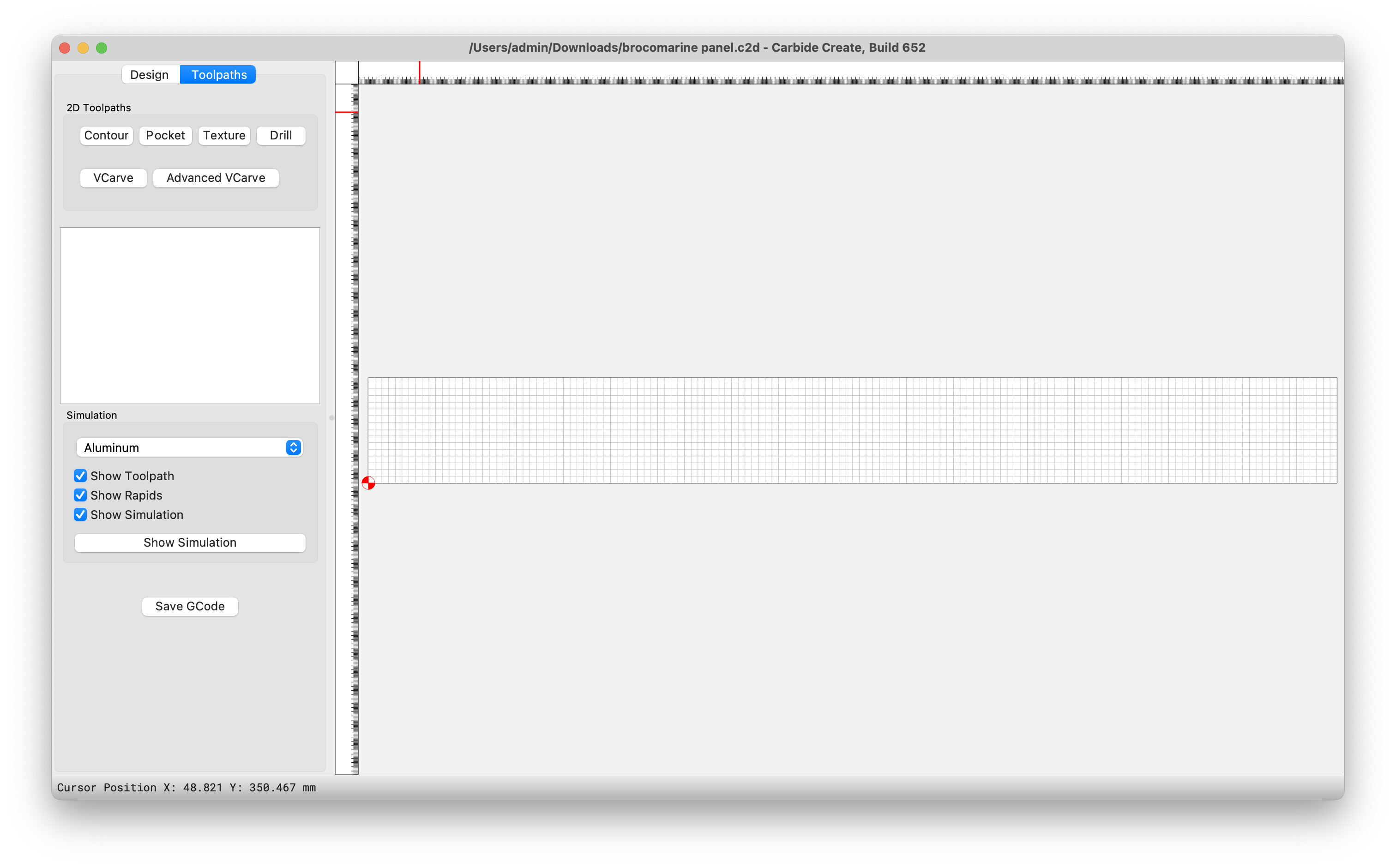
I could open both files and they are both empty containers without any design or toolpath information inside them. Here are the images from both files.
brocomarine panel.c2d (532 KB)
Design:

Toolpath:
Job Setup:
brocomarine panel.2.c2d (492 KB)
Design:
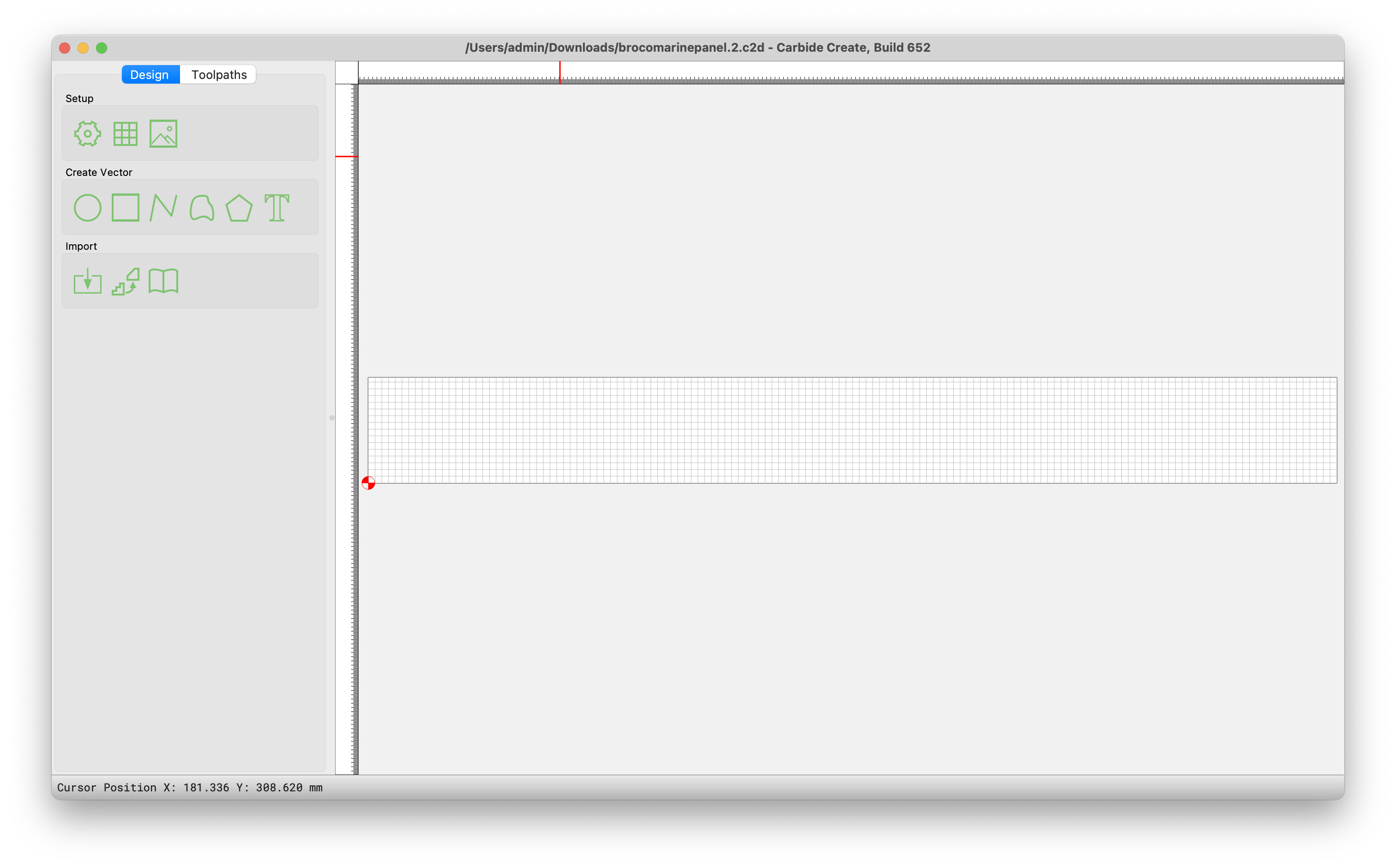
Toolpath:

Job Setup:

If you could post the actual files you have used, it would help with diagnosing the issues.
Maybe @WillAdams can figure it out. I am using the basic CC to open the files. Build 652 is the version I used.
the file was created in V764 ![]()
2 Likes
![]() Thanks Tod (sotto voce) Smart*ss
Thanks Tod (sotto voce) Smart*ss
What a surprise! It now works… in V773. I had not upgraded because later CC versions were designed to run in Mac Os 14xx which I could not upgrade to because of old hardware. I am running Ventura (MacOs 13xx) but it works just fine.
1 Like
Ha, funny!! Being a musician I actually got that. I frequently tell my grandkids, “Pianissimo!!” ![]()
2 Likes
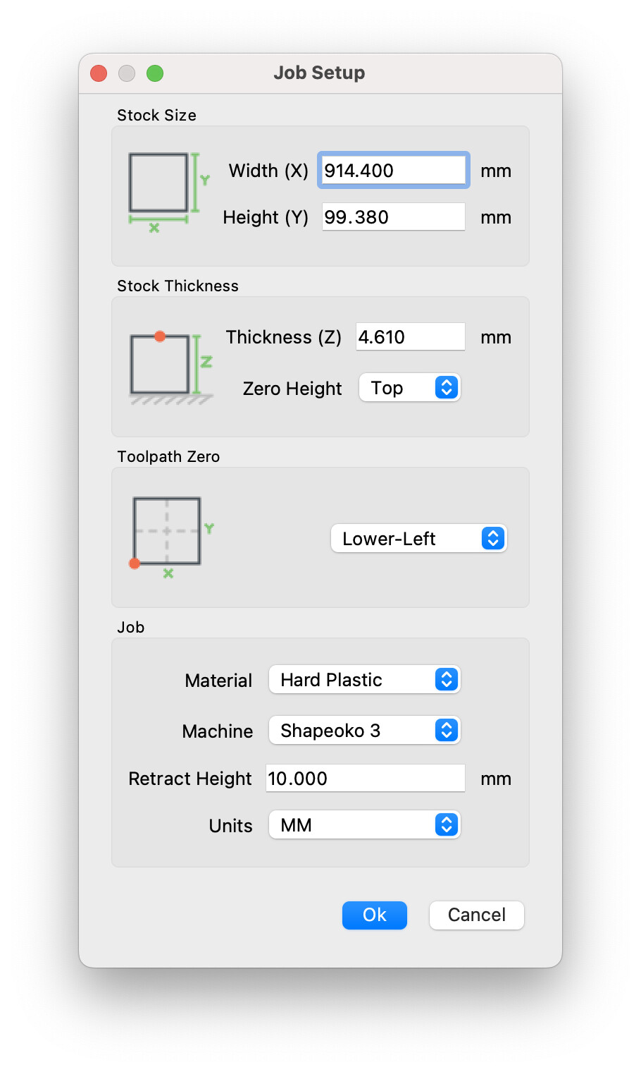
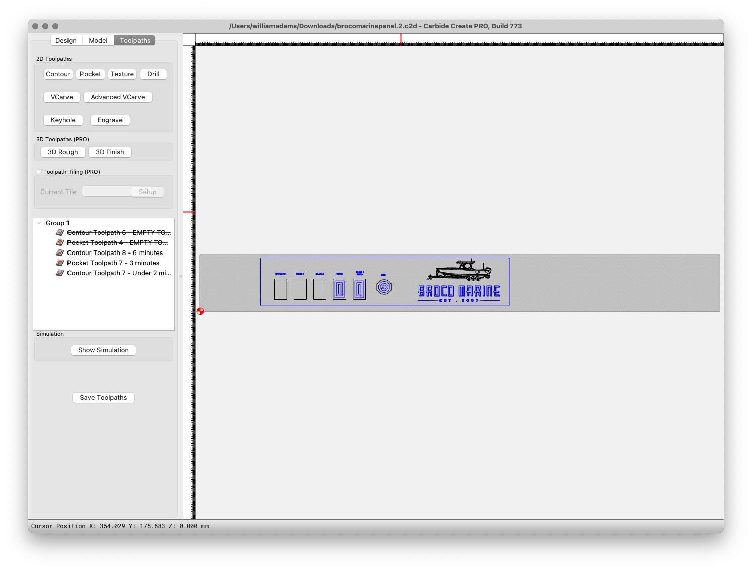
Looking at the file broncomarinepanel.2.c2d one can see this:
Job Setup Parameters:
Stock thickness is 4.610mm
Zero height is Top
Retract height is 10mm
Stock width is 914.400mm
Stock height is 99.380mm
Origin is lower left
Design Parameters:
NAV/ANCH Rectangle with square edges: 22.062mm Wide x 36.280mm High
BILGE 1 Rectangle with square edges: 22.062mm Wide x 36.280mm High
BILGE 2 Rectangle with square edges: 22.062mm Wide x 36.280mm High
HORN Rectangle with square edges: 22.062mm Wide x 36.280mm High
BILGE 1 AUTO Rectangle with square edges: 22.062mm Wide x 36.280mm High
USB Circle with flat sides: 26.449mm Wide x 26.000 High
Contour 7 Rectangle 437.95mm Wide x 95mm High with 2mm radiused corners
Contour 8 All text requiring to be engraved
Pocket 7 Six 2D geometric shapes
Toolpaths:
Contour 7 1/4" diameter selected for cutter to cut to a depth of 4.826mm in a single pass. Plunge set to 381mm/min. Feed set to 1905mm/min and RPM set to 18,000 per minute. The contour toolpath was cut on its centre and tabs of 12 x 3mm were provided.
Comments: The depth of cut (DOC) pass depth is greater than your material depth. The 100% tool engagement (presumably you are milling in a conventional rather than climb milling direction) and DOC of more than 50% of the tool diameter, is driving the tool harder than necessary and will shorten tool life by blunting the cutting edges.
The plunge speed equates to a linear distance of 15 inches per minute. If the workpiece material is resistant to cutting, the high RPM will push the tool through it but that feed speed is also equivalent to 75 inches per minute. That is forward travelling speed of 1¼" per second. I suspect that the combined travelling speed and plunge speed are high. (Is the tool discoloured at the cutting end?) With 100% tool engagement, it is likely to be on the uncomfortable end of cutting easily without hurting the tool or the workpiece.
Presented with the same job, I would probably opt to reduce the pass depth to 1mm, where the plastic was hard and 0.5mm if the plastic was soft; at least for testing where the machine was comfortable. I think I would also start with a plunge speed of 200 or 250 and a feed speed of 1000 to 1500. The RPM is fine. 100% tool engagement is a quick way to get into trouble by generating too much heat or loosing stepper motor steps by cutting against too much resistance.
The thinner tools will usually suffer from noticeable deflection to some extent and breakages can be a nuisance with high lateral loading and 100% tool engagement. Tabs are helpful and yours are almost a full ¾ of the workp[iece height. In my experience tabs should be as a small as can reasonably hold the workpiece intact so that the amount of cleanup and removal from the stock is minimal. In this case I would have placed six tabs 2mm wide by 1mm deep. One in the centre of each end and two equidistant along each long side.
more anon…
1 Like