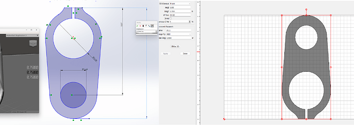
I measured my STL in mesh mixer to make sure this is a you problem but what is going on that is making my x y scaling off by a factor of 25?
25.4 hmmm thats suspiciously metric looking… which is weird because I modeled it in IPS, exported in inches, my CC is in inches?
Try opening in a 3rd party tool such as Microsoft’s 3D Builder to check the dimensions? Resave from that tool and then import into Carbide Create Pro?
I opened it in meshmixer and it understood the coordinates perfectly I think this is really a non issue and I’ll just scale by 25.4 no sweat.
I just needed to understand what it was doing and this seems to check out so now I should be able to do my knife scales no prob!
This is a common problem with STLs, they don’t seem to have clean unit metadata, Autodesk Fusion has trouble importing them too, there are various tricks around setting your default units before opening the STL dependent upon whether the source program exported in modern or IP units.
When I import an STL to CCPro I first open it in FreeCAD and note the actual X Y Z dimensions. Then in CCPro I draw a bounding box with the correct X Y dimensions and import the STL to that box. If it imports to the correct bounding box size you’ll see the X Y Scale at 1.0
I think I remember a satellite that crashed into Mars because of a bad conversation from or into metric
Scale by 25.4 or .03937 , whichever direction to get the right result
That’s good as long as you dont mind being off a tiny bit. In this case I can just work in inches and have an XY scale of 25.4 or I can work in MM and have an XY scale of 1. Either will be as accurate as possible without having to do workarounds.
Thanks for the info, I’m still learning alot of this and eventually I’ll probably just use Solidcam.
Interesting. The project I’m working on now, it doesn’t seem to matter if I work in inches or millimeters, my X Y Scale stays at 1.0. I don’t think X Y Scale is an actual measurement, I think it’s more of the relationship of X and Y to each other. A percentage of one to the other. I’m sure one with more knowledge of CCPro could better explain.
In your screenshot, the image on the right, you can see the two holes are oblong. If the Y dimension is correct and you drag the X out to the left or right, does the X Y Scale get closer to one and the holes look rounder? How about if you drag it out a distance that equals 25.4% of the height?
The xy scale is a scale of the units of measurement in the STL which seem to only translate to mm in Carbide Create Pro from what I can tell sounds like as that gentleman above said the metadata doesn’t store alot of information about what the units are and so since the Shapeoko works in millimeters it makes sense that Carbide create would go straight to millimeters.
this is precisely it! CC assumes the STL is metric. So entering your scale manually at 25.4 should get it back to nominal size in inches.
I often find CC imports and scales to the size of the stock setup so you have to watch it.
Where the same file in F360 will be shown at the correct part size.
So after a tonne of testing it turns out CCpro’s bounding box is not only incorrect It’s creating angles where there are not angles. The STL scaling is also quite off. The STL itself shows this when measured in CC. and you’d think it would be doing this because of the step size but the math showed that to be false, as it was a factor of 10 steps it was off by plus it differed in the x and y axis. I guess for now we’re stuck waiting for the team to finish doing the algorithms to keep that in check with step size.
Which tool made the STL? Using what scaling/measurement unit?
If you open the STL in a 3rd party tool what dimensions does it show?
I’ve found that opening an STL in Microsoft’s 3D Builder, then re-saving, then importing into Carbide Create Pro yields dimensions which match those from Microsoft’s tool.
I work with CATIA (made by Dassault - a French company) at work, and we use the IPS coordinate system, but when STL files are saved for 3D printing, then opened with PrusaSlicer, they have to be scaled to 2,540% (25.4 x 100%) to be the correct size, or “Import file - imperial dimensions” to be the correct size.
I work with SolidWorks (made by Dassault - a French company) at home, and I use the IPS coordinate system, and when STL files are saved for 3D printing, then opened with PrusaSlicer, they open at 100%, with no scaling required.
Okay. Cool. Thanks Dassault.
Heads up Microsoft has delisted and blocked access to all embedded download links for it.
Edit found it on a shareware site.
I also work with Solidworks and it is exporting very functional correct STL’s. This must be why Rob was asking about a proper STL to scale importation as the current system clearly gets overly creative. It’s not even doing it because of step size as it’s size is off by 10 steps or .12mm.
It measures correctly in that program but the revised file is still incorrect I think it’s a technical limitation of CCP at the moment. It’s only 5-10 thousandths of an inch depending on the axis.
If you then re-save in a new file from 3D Builder does that file then open at the expected size?
