I wanted to cut a t-track slot into a piece of CLS timber and designed it in CC and cut it in CM (files attached).
OK, I could have used a router table (10 minutes) or a table saw (15 minutes), but decided on using my XXL as I could be repeating the task in the future and thought using CC and CM would do just as well (but maybe take a little longer).
The CLS is longer than the XXL can cut, so I designed the toolpath to cut some of the slot, with the intention of sliding the stock along a guide and running the job a second time. Based on this premise, I (initially) only re-zeroed the Z axis, but the edge of the second cut was 2mm out along the length of the stock - along it’s whole length, as shown in the photo:
Strangely, this is parallel with the original cut along it’s whole length, so I have no idea what went wrong, but I know this:
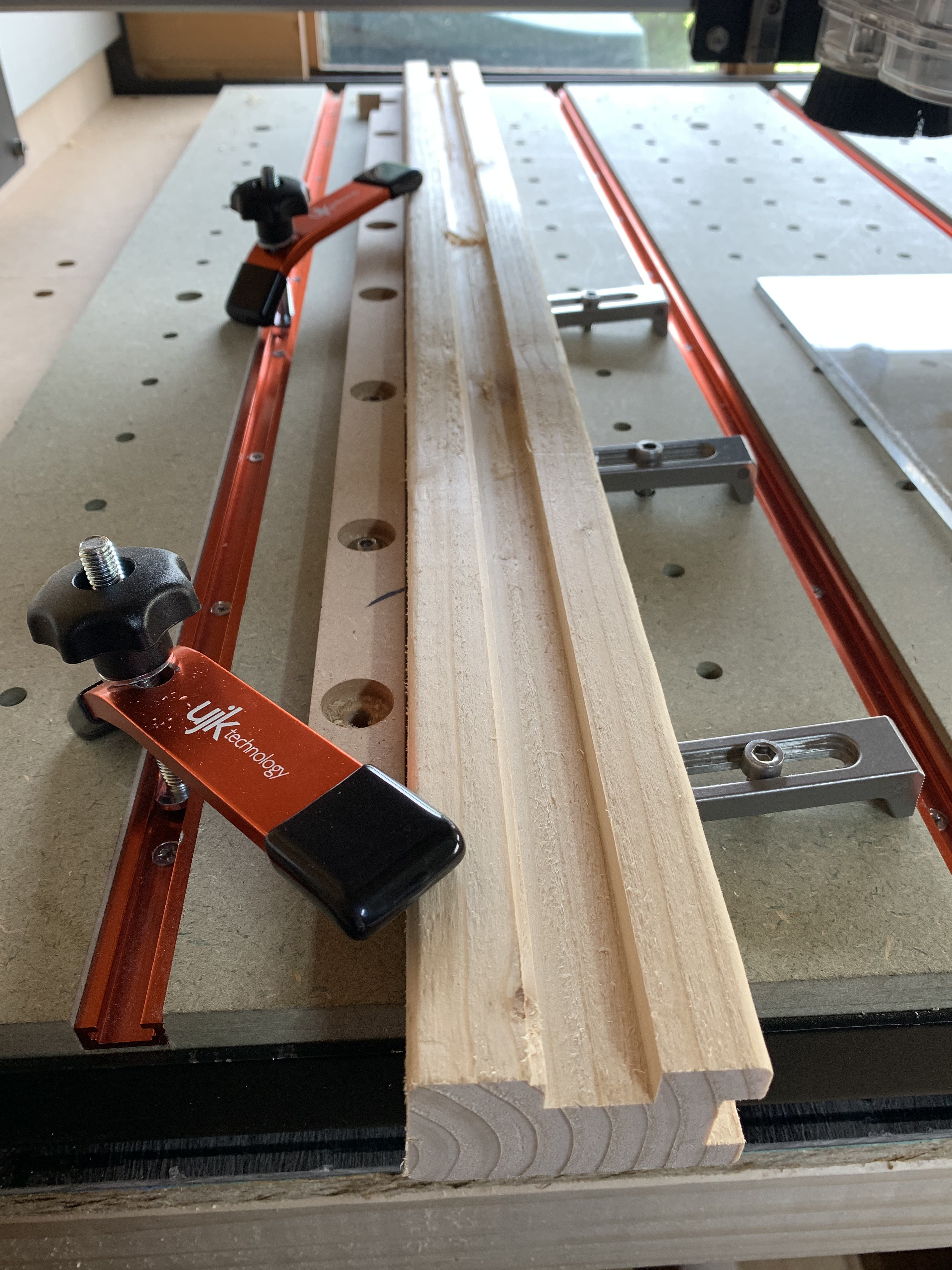
The stock is pine and isn’t known to be particularly straight and parallel (here in the UK, at least) but this piece is fine, is clamped flat along the guide (just visible to the left in the photo) and the guide is parallel to the waste board. All I did was release the clamps, slide the stock forward and re-run the cut.
I moved the workpiece, but only moved it forward and re-clamped it into position.
The clamps are separate and the guide didn’t move. I was careful to ensure the stock was held against it, along it’s whole length when I put it back together, and I think it would have been obvious if any detritus had fallen between the stock and the guide when I clamped it.
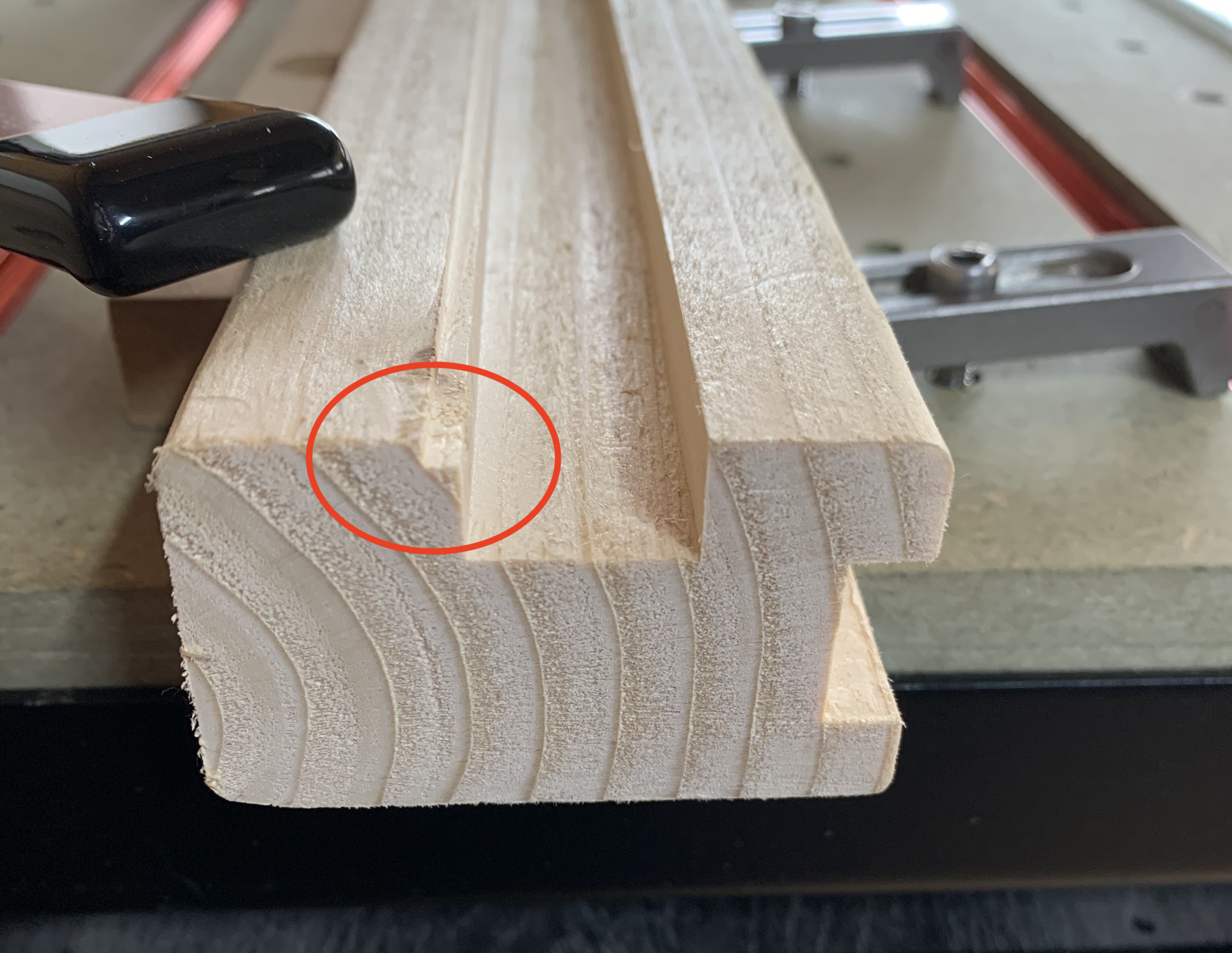
Could you add a little more detail to what we are seeing in the picture? Is the deep part of the cut from a previous cut or from the second cut?
If the stock is the same size as in your .c2d file, then it looks like the bit you’ve circled actually needs to be cut out so the slot is central and equidistant from the edges of the wood.
The deep part is the original cut, before I moved the stock towards the front, to cut the rear part. It was during this second cut that the issue became apparent, so I kept tweaking the X zero until the cut lined up with the first one.
The bit I’ve highlighted is a third cut, over the original to see how far out it was - essentially, the project is trash now, so I did this to see what the difference was.
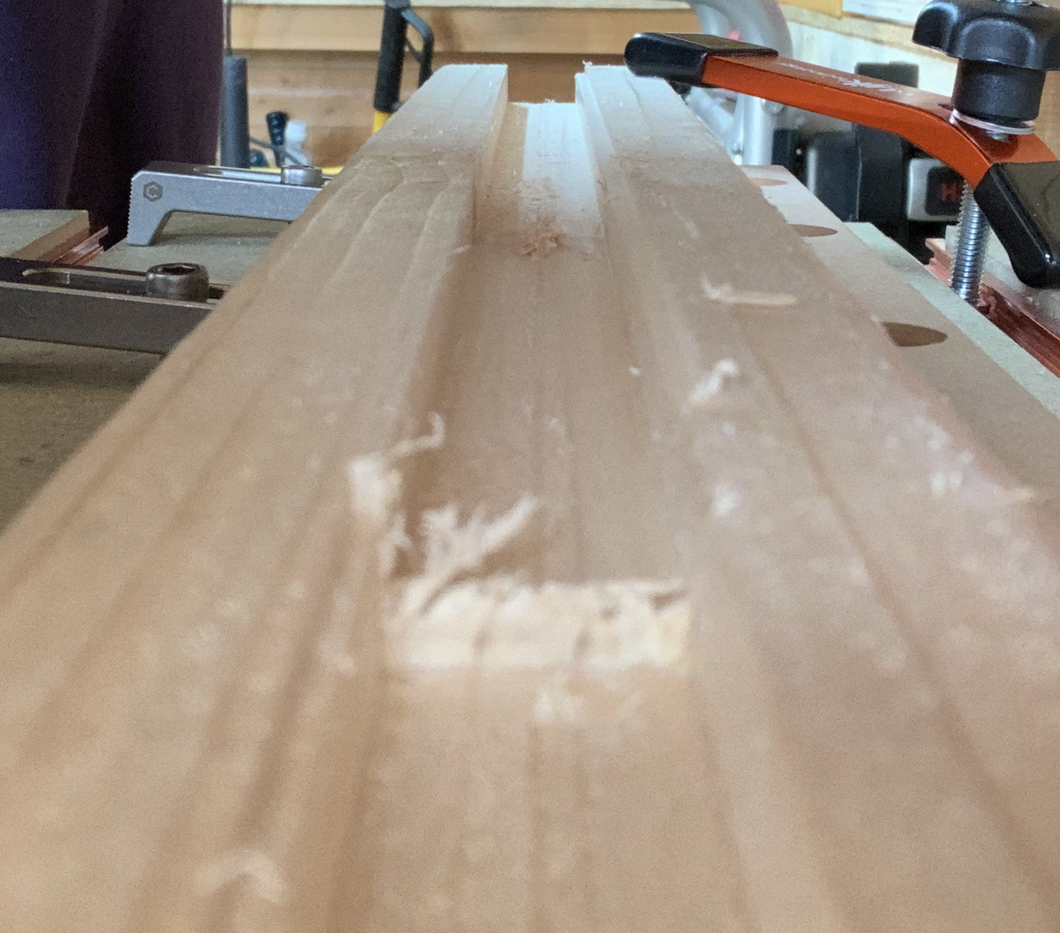
Bizarrely, the depth of cut was different too. I measured them and found the first cut had only been 11.5mm deep and the second 15mm, so I’m even more puzzled (sorry about the focus):
The design shows this being central and the stock is correctly sized, but this is coincidental. The main purpose of the cut was to be parallel with the left hand side of the stock (as viewed from the front). This photo might show it better:
This is a long shot, but the pull off distance from the sensors is 3mm. Is there a chance you homed the machine but didn’t zero everything on one of the passes/times ran?
With this project, I secured the stock and zeroed the X, Y and Z axes for the first cut, assuming this would be all I needed to do, but I ended up having to incrementally adjust the X axis to take account of this ‘shift’.
Thanks for the extra details - they are helpful in that they make everything more confusing!
It looks like you slid the stock in the other way around for the second cut. As in, the guide was against the slotted edge for cut 1, and the unslotted edge for cut 2. This is probably unlikely but the sort of mistake I would make.
Another possibility is that your sweepy caught the top of the ujk hold-down clamp during some pass and you lost a 3mm of travel.
I definitely didn’t do that! What on earth do you take me for
I was conscious of the close proximity of the end mill to the clamp, so I was sat on a stool watching it from the front, feed-hold button in reach, but it cleared it well enough.
Darned pixies! They get just about everywhere, these days
In your #2 post, did you mention that you disabled the BitSetter to run the first operation then enable the BitSetter to run the second operation? Does that require you to re-initialize the machine?
At the end of each run the machine would move to the rear and wait, I’d rapid move it to X/Y/Z+6, and jog the Z axis down to the new surface, reset Z zero and run the program again, so I don’t know the answer to that question.
I didn’t think it would be necessary to do that, but I’m cutting a project today, so I’ll give that a go, but by ‘home’ do you mean jogging the machine to home position (NE) or re-initialising it?
This has all the makings of “simple” lost steps. Once you re-initialize (Home) the machine, all of that is reset, your absolute reference is regained.
My thought was that if you ran the cuts, homed, went back to zero and noticed it was off that would mean that position was lost at some point during the cut (or in between the two). You may never know why, but it is probably not a setup issue or software bug.