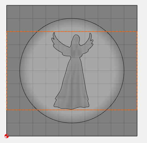
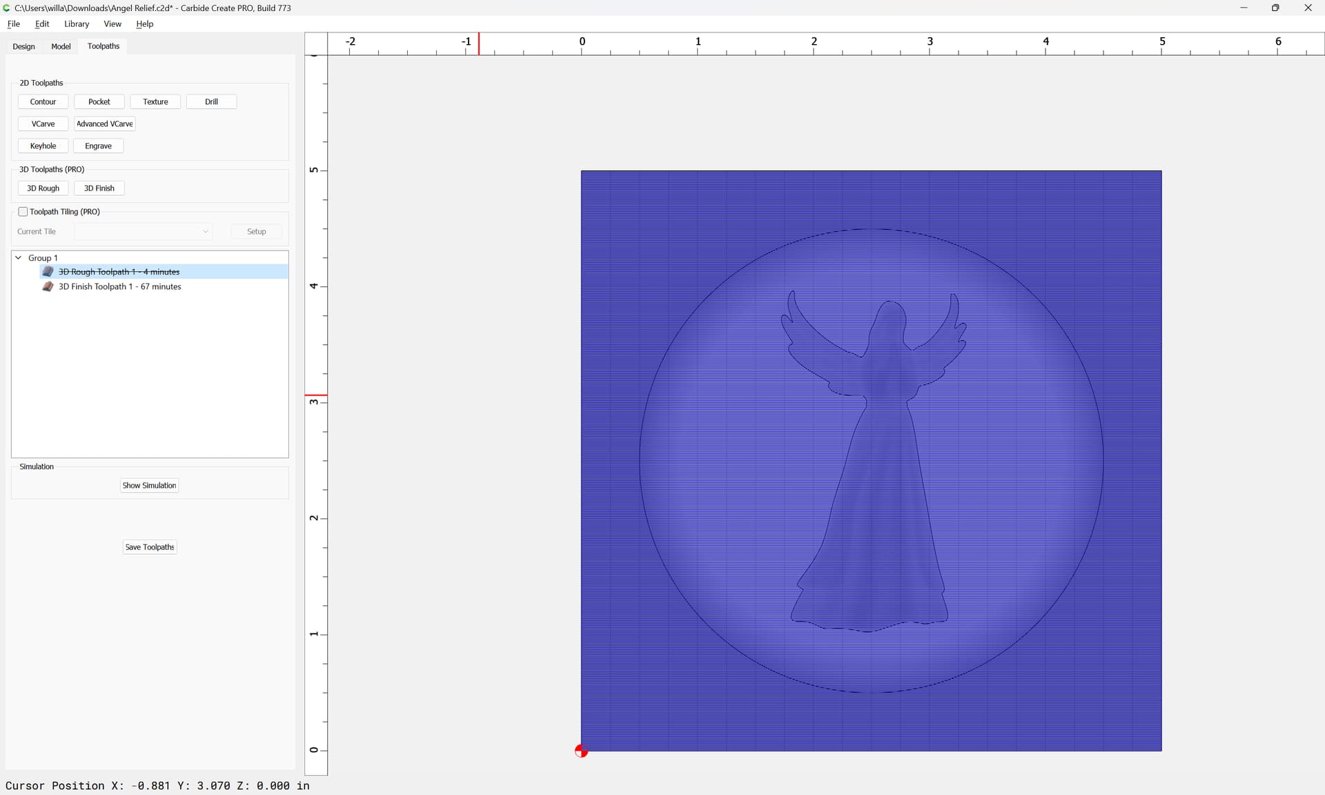
I am trying to do a 3D carving. First one I’ve done. I have a 5"x5" workspace and the model I used has a 5x5 rectangle, flat with a height set add wood depth minus 1/8", a 4x4 circle, round with a height of 3/8" subtracted, and then an angel stl with a height set to 3/8", everything is centered.
Used a 1/4" straight bit for the rough cut an Amana’s 46281 1/16" ball tip for the finish cut.
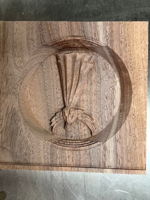
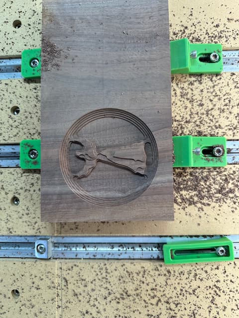
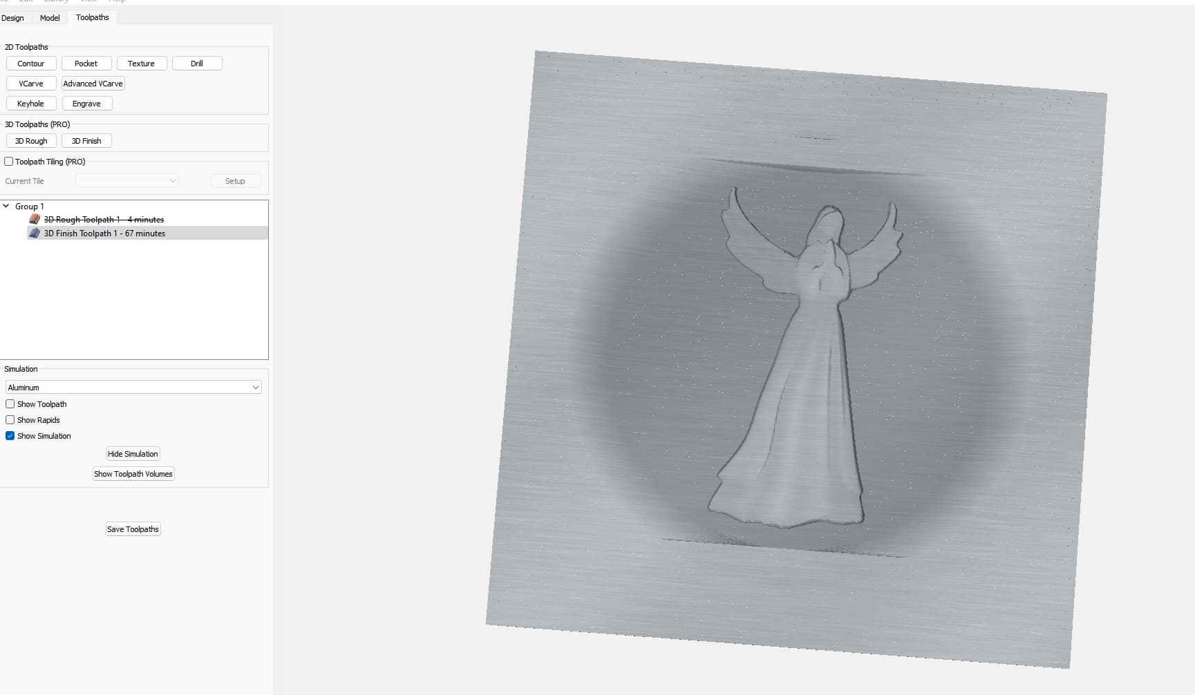
The Carbide Create app shows a nice clean recess. Cutting however shows the 1/4" steps on the top and bottom of the circle recess.
I will include the c2d file and the rough and finish images.
That’s a tough one. Is it possible you generated the path once, saved the g-code, then changed the path without saving the g-code again?
It’s not the wrong scale, and it doesn’t look like it skipped steps. The angel looks correct.
It’s unlikely that the toolpath would be missing both start & end. And the start is the part that turns on the spindle, so if that was missing the spindle shouldn’t have come on.
Did you, at some point have a rectangle smaller than the stock size?
A couple observations, unrelated to the error…
cutting the flat top with the 3D toolpath wastes a lot of time. Unless you want that surface scalloped from the ball mill, I would surface the top off flat & only cut the depression area with 3D.
I would also run the finish path at 90° so you’re going with the grain, instead of cutting across the end grain.
I would not have changed dimensions after saving the gcode.
I selected the 5x5 rectangle and then did the rough and finish 3D paths and saved the file.
Thanks for the comments on the flat top. Wasn’t quite sure how to go about doing the inset dish area. Whatever I tried, visually in the program seemed to go thru the wood and the only way I got the visuals I wanted was to use that 5x5 rectangle. It set the height to t-.125 but could have just used t, unless I’m going about this the wrong way. Also don’t like the fact in the software that once you select “done”, you are actually done and can’t go back and make any changes.
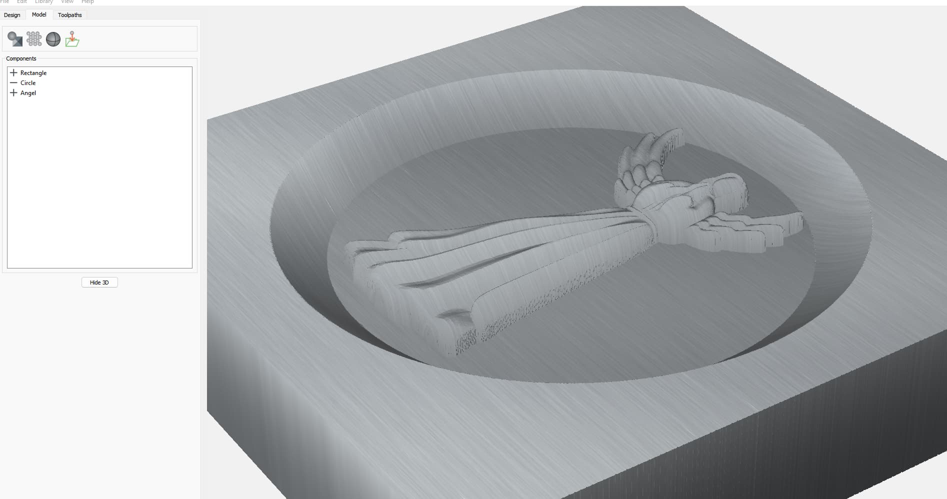
I’m able to download the c2d file and open it with CC, and the objects show up. Don’t know if it matters or not, but this is 3D code and requires the Pro version.
I’m thinking there’s another rectangular object in the 3D Modeling list which is no longer visible & should not be there, but it’s digital ghostly remains are still interacting with the model - a bug.
Perhaps the C3D team can have a closer look into the file to figure out what’s going there.
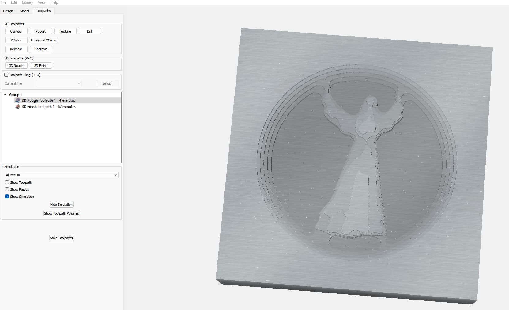
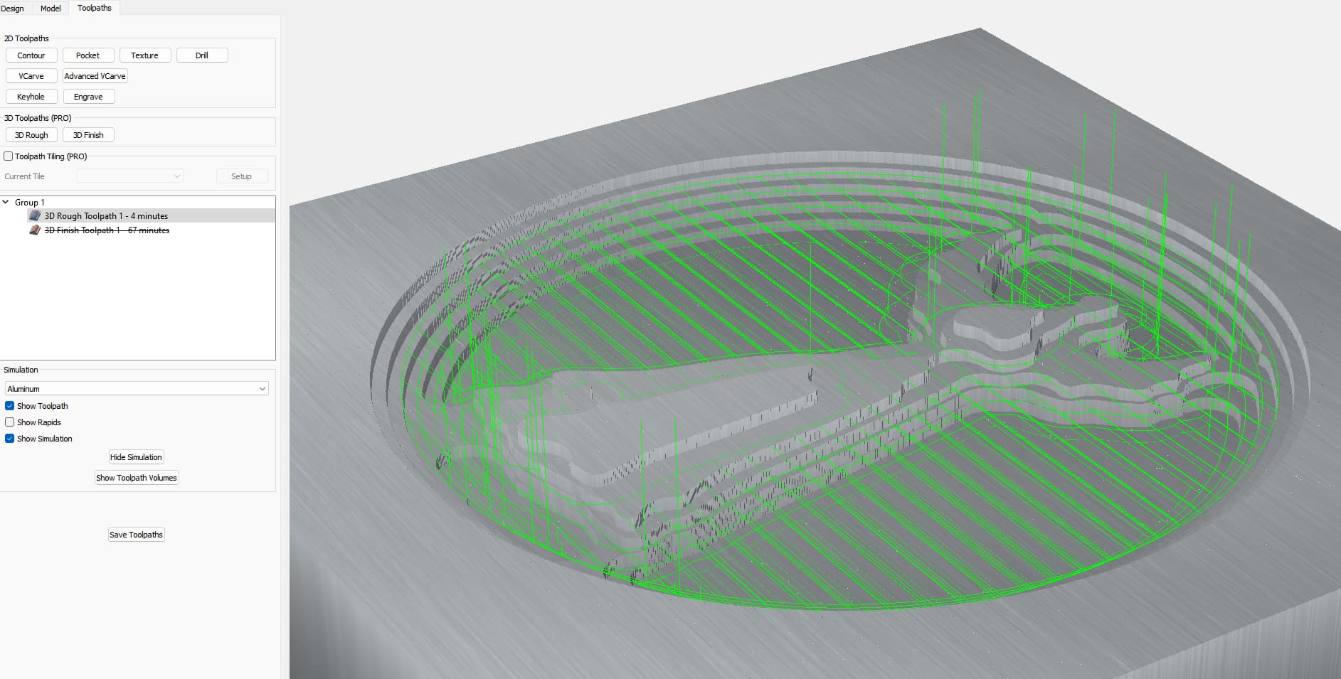
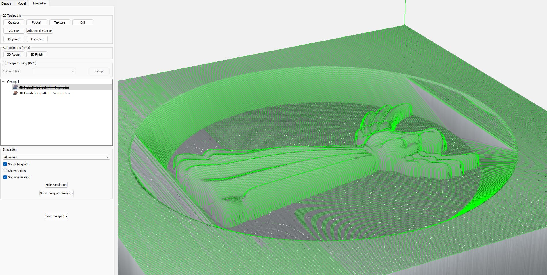
I’m on v764. The 2D toolpath simulation does not show the issue as the 3D Finish toolpath is rasterizing across everything as it should. It’s just not following the 3D surface of the model as expected & depicted in the 3D Modeling tab. The 3D Roughing toolpath seems to follow the model as expected.
I do not have the Pro version of CC. What export options do you have from CC Pro? I can look at .nc files easily if you can export them from CC Pro. Alternatively; CAMotics is free to use and should show you what the file will look like when carved.
Another option is to use the web based NC Viewer which is also good.
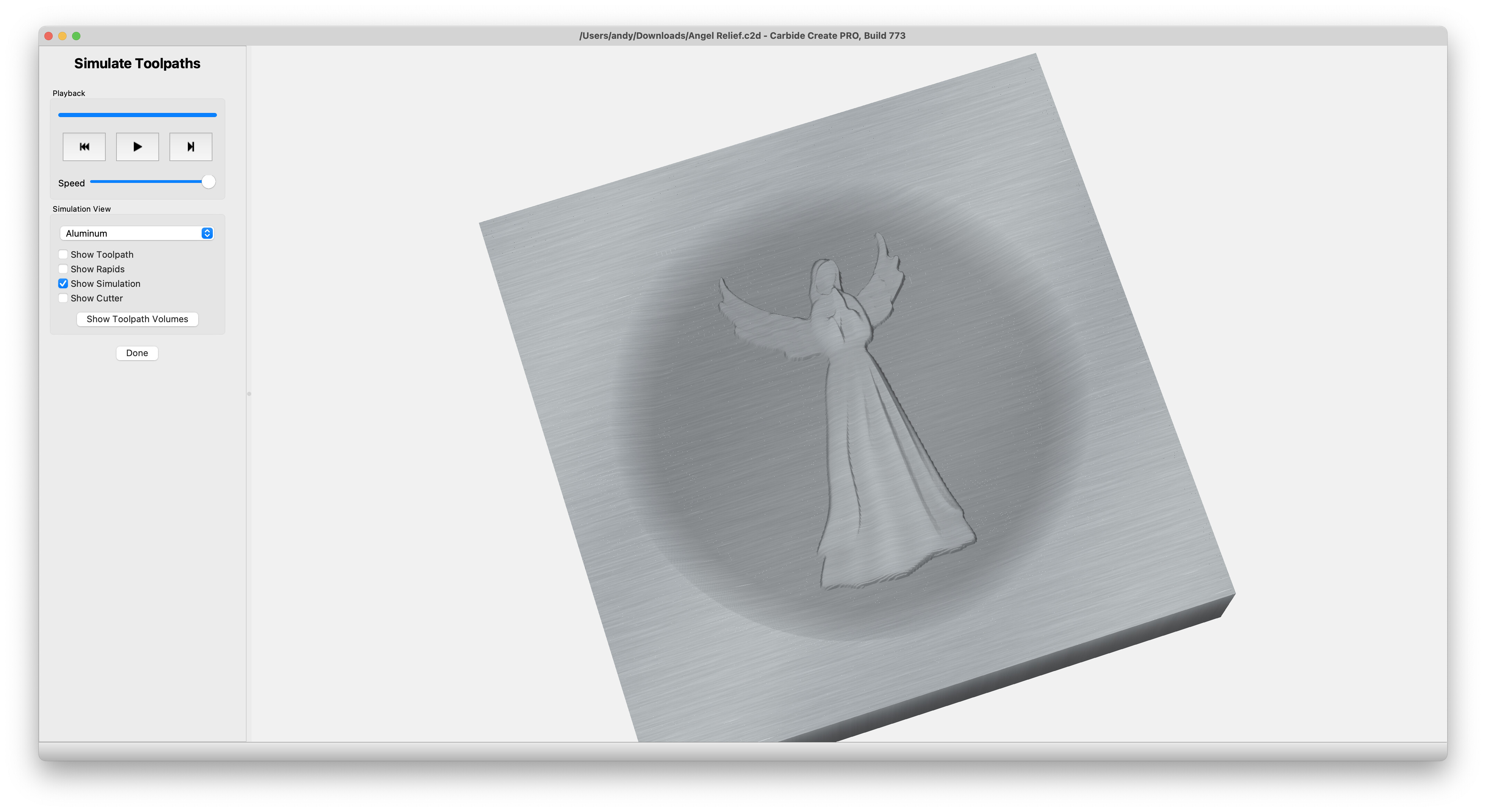
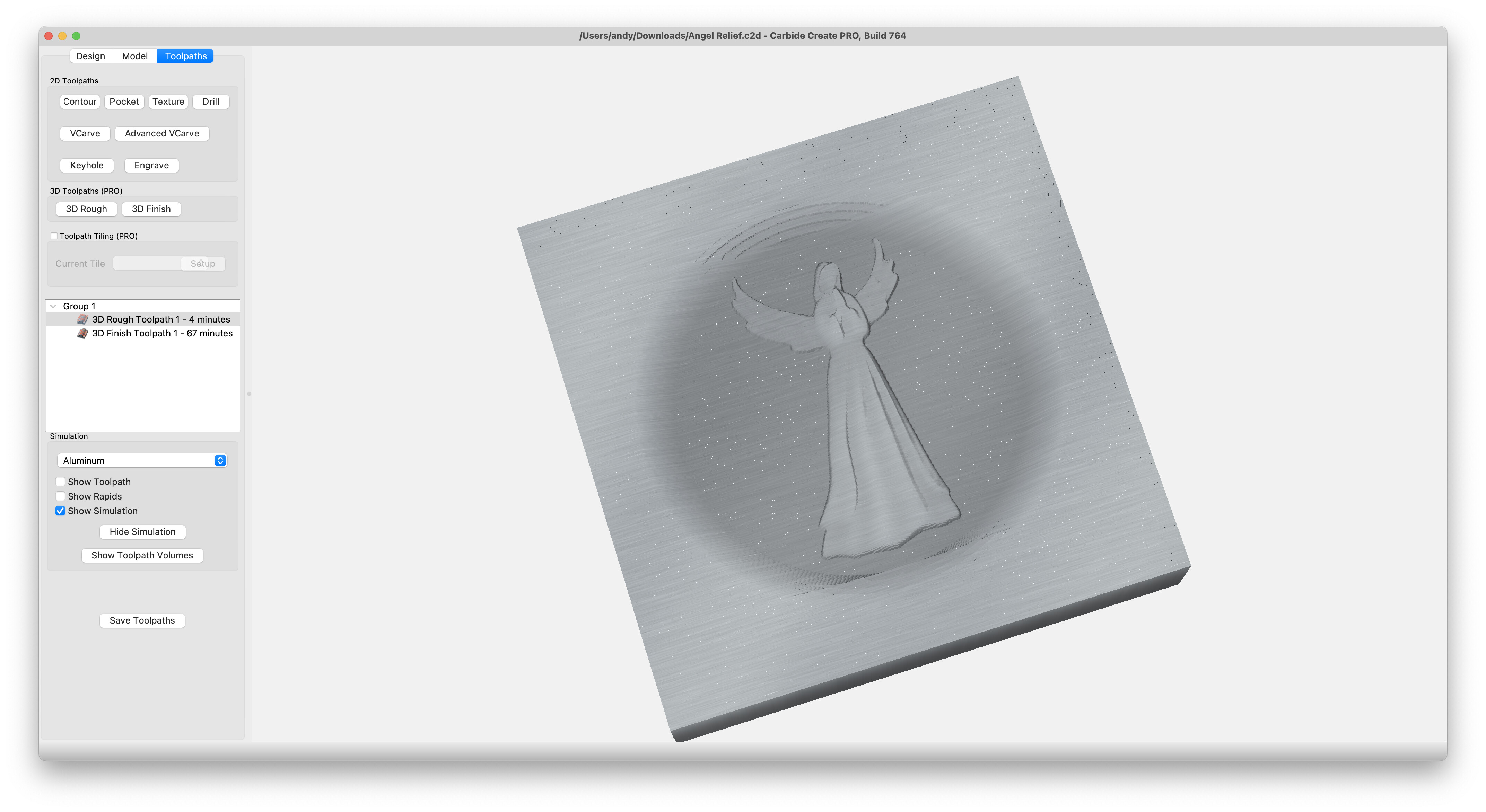
I downloaded the file and simulated it in CCPro and everything looks good. There is no problems that I can see and the steps are all cleared out.
I do have a note for you though, if you are running a 1/16" endmill for the finishing of the angel, it will lose a lot of detail all over the body. You could draw a polyline around the angel and create a second finishing toolpath with a 1/32" ball nose endmill and the detail will become very distinct. This second finishing toolpath will only cut around the angel and reduce the runtime of not cutting the dip in. Just a suggestion.
I had a 3D dragon I was working on and the detail was just crap on the 4"x8" board I ran it on. I even shrunk the design down to a 3 1/4"x6" board and ran the 1/32" ball nose endmill across the dragon and the details were all there.
I added a polyline around the angel and created a second finishing toolpath with the 1/32" ball nose endmill and the added time was only 15 minutes, but the angel came out a bit more clearer. The face doesn’t have much detail in it but I think it added some finer looking shapes to the carving.