I have an engine part i have been trying to make for a year. I have an .stl file that I have test printed with a 3D printer, and cut it with renshape on a desktop cnc to be sure it is right.i am using, trying to use, a Nomad3 to do in aluminum. Whether its the machine, the software, or me, I cannot get it done. Always something stopping the process, lately it has been that the machine does not stay centered, although the xy zero doesn’t move. I do not think the Nomad can handle this size part. It fits within the posted parameters but just cannot get it done and I am tired of trying.
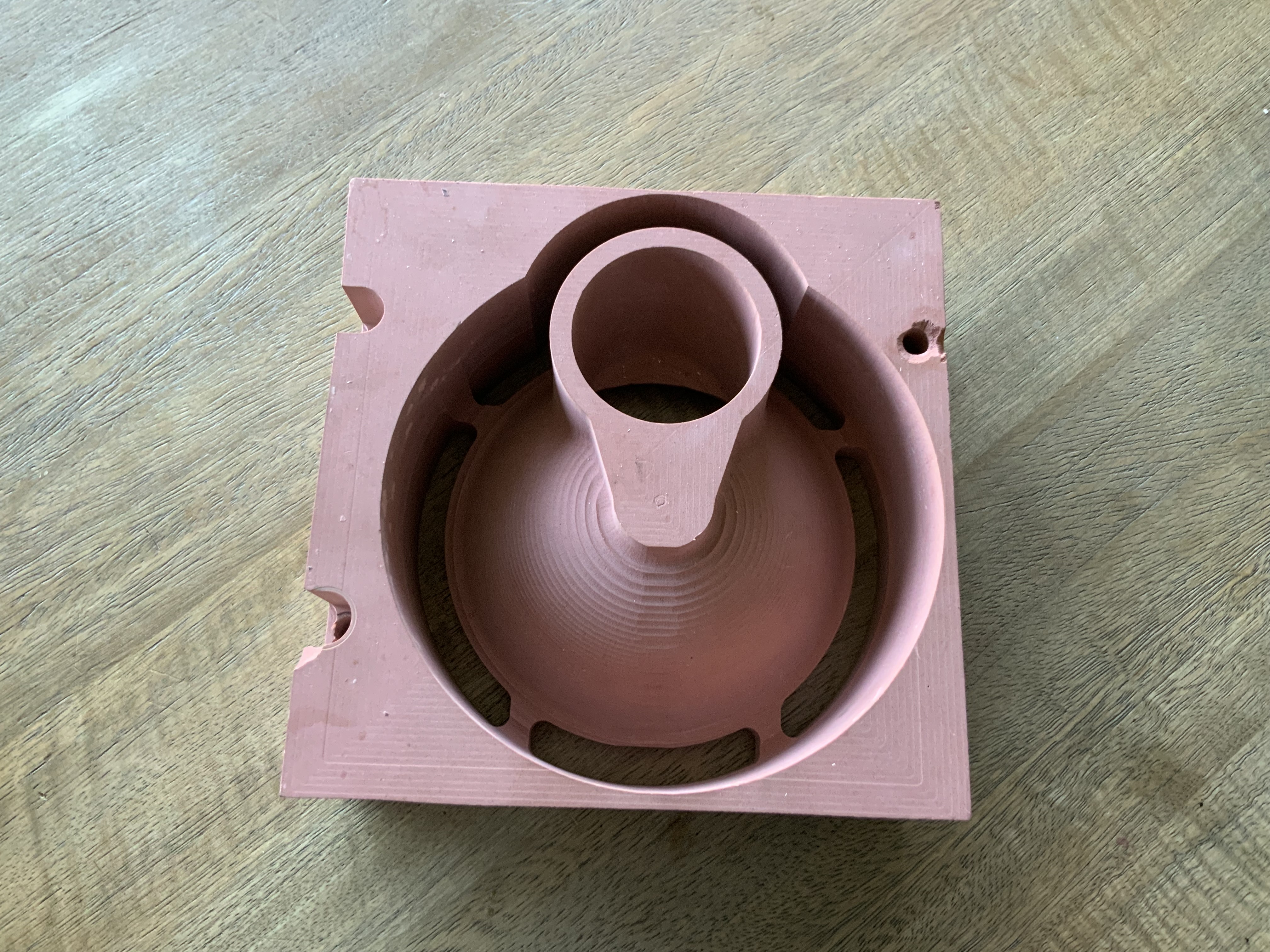
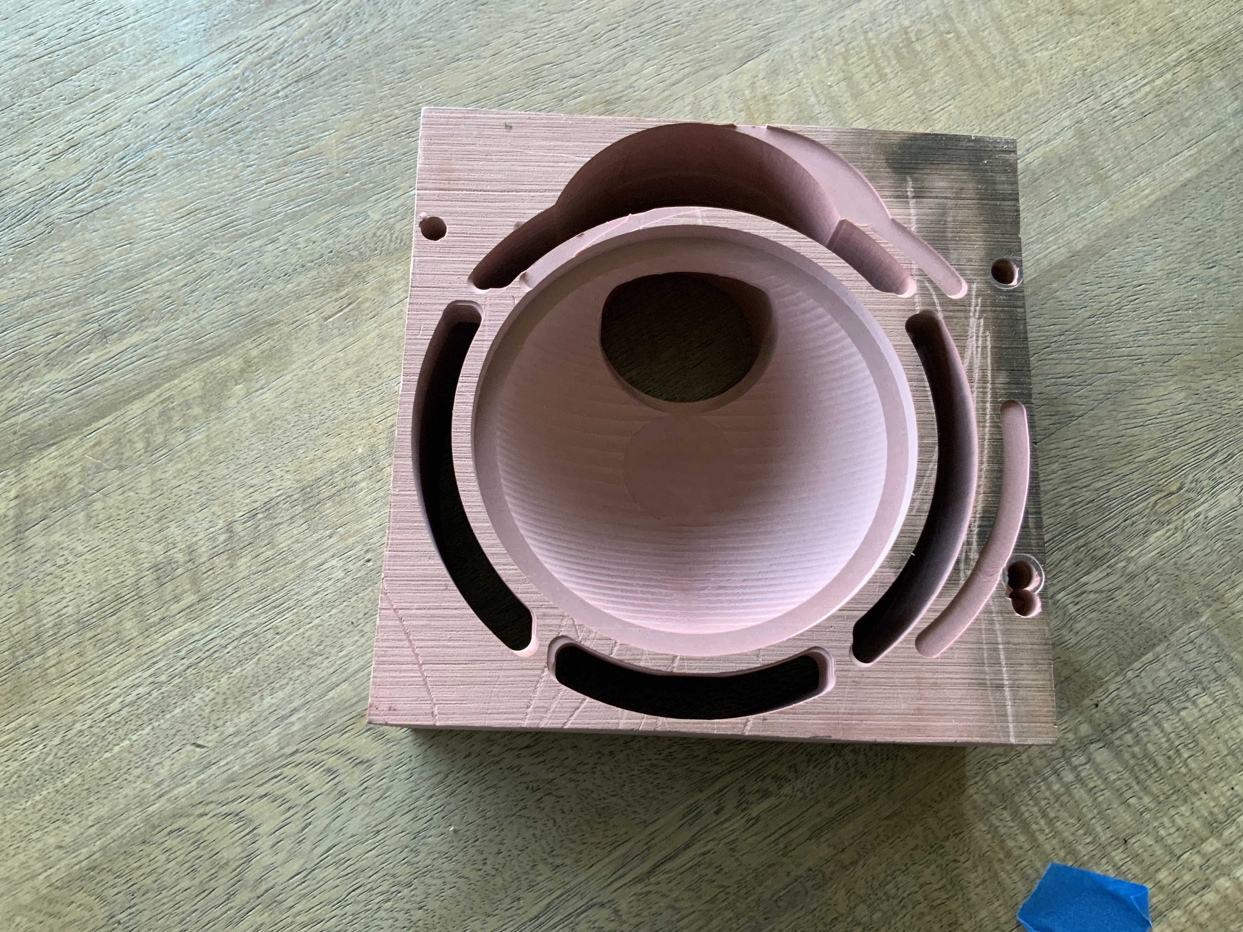
Anyway, if someone would like to make it, I will pay for your services. We can agree on a price and I will send the .stl file; I can even mail you the aluminum stock. Pictures below of one of the renshape proofs.
challenging, yes. I do have the long endmills, and I was able to easily cut it with renshape. The machine (or software?) keeps going off-center when I try to do aluminum. and after I abort, I check the xy zero and it is still right on. My guess is that my machine setup just cannot handle it.
I have been through this sooo many times. I can’t do it anymore. I am using what was recommended by Carbide for 6061-T6511 and it doesn’t work; I have tried variations both up and down. But I am not going to spend more of my time typing it all out and then trying something else that doesn’t work. The machine does not stay centered, for some reason that no one can give me. As it gets lower, this last time it started moving left; other times it was all over the place. The xy center is always right on after I abort and check it. I am done trying, and I am done spending time trying to diagnose it. I never get a reason, I only get theories that don’t work.
If I were milling this piece on a HDM, and I am pretty sure it would be possible, I would use an adaptive 3d toolpath and I would need a .5 gap around the piece instead of trying to slot it, so it would need a 8 inch wide piece of aluminum. I would probably be using 1/4" reduced shank 3 flute and a 1/4" reduced shank ball nose for the deep parts.
Thank you for the post. I like the idea, but I do not understand how you would do this. How do you create the gap? Don’t you have the same issues to do that, to create it, that you do without it?
Meshcam does not offer an adaptive toolpath. Maybe part of my problem is the software and/or machine? I can research and try for a year but if the setup I have cannot do it then I am set up to fail.
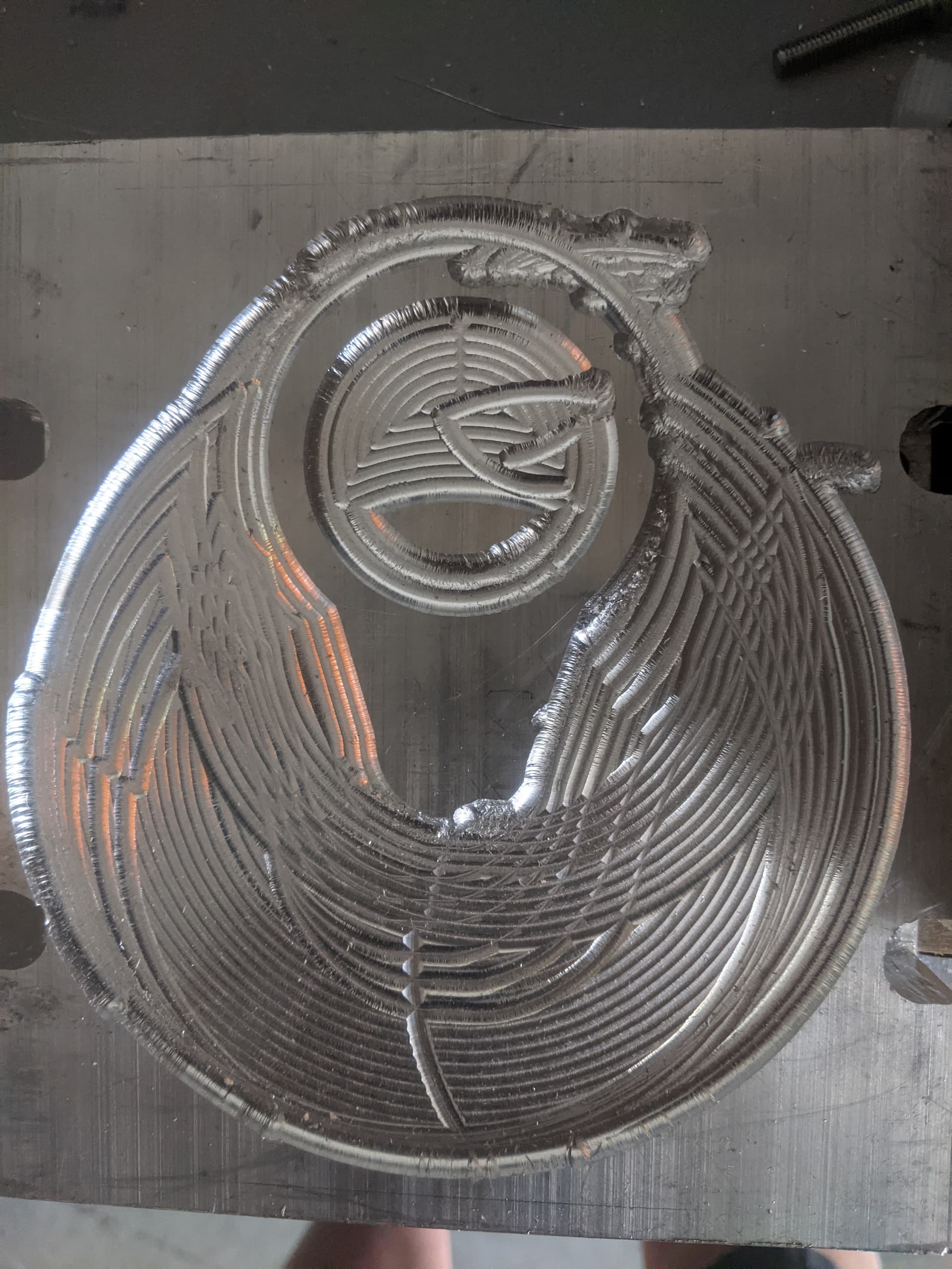
I have been using 1/8" bits. I tried using what you recommend. The 1/4" ball nose was one of the times that the machine completely went off the rails and was doing random patterns. pic below. Carbide told me it was ‘theoretically’ that the machine does not have the torque required for a 1/4" with 6061. No explanation on how that issue would make it start doing what is pictured. On a separate occasion tried a 1/4" double flute. This stopped the spindle as soon as it touched with a super-slow plunge rate and .004" penetration.
Can you export the Sketchup model as a Step, Iges, or dimensioned drawing?
I would want to cut this from a real model rather than an STL (faceted body).
If you can send one of those formats, I can get you a quote.
The short answer is no. But I was able to export a .dwg, open that in Autocad, export an .iges, open that in Autodesk inventor, then export an .stp.
BUT, I have no idea of the value of either the .iges or .stp. I have sent them out for some ‘automated’ quotes and get an error message back. I will send you all four. .stl, .dwg, .iges, .stp
Hi James,
I would only use the ball mill to smooth down .02 of material for the curved surfaces.
Please send me the model, I will attempt to re model it with Fusion 360.
yes i get that. This was at about attempt 12 I was trying anything to get it to work. My thought was that the ball nose wouldn’t cause as much friction (and less required torque) and might actually work. But it was not to be. after that I switched to exclusively 1/8"
It does fall under the category “You get what you pay for”
However, I have designed 3d parts in autocad, exported the files and used Meshcam to create the Gcode. However, I used a mill I converted to cnc, that has cutting area than the Nomad.