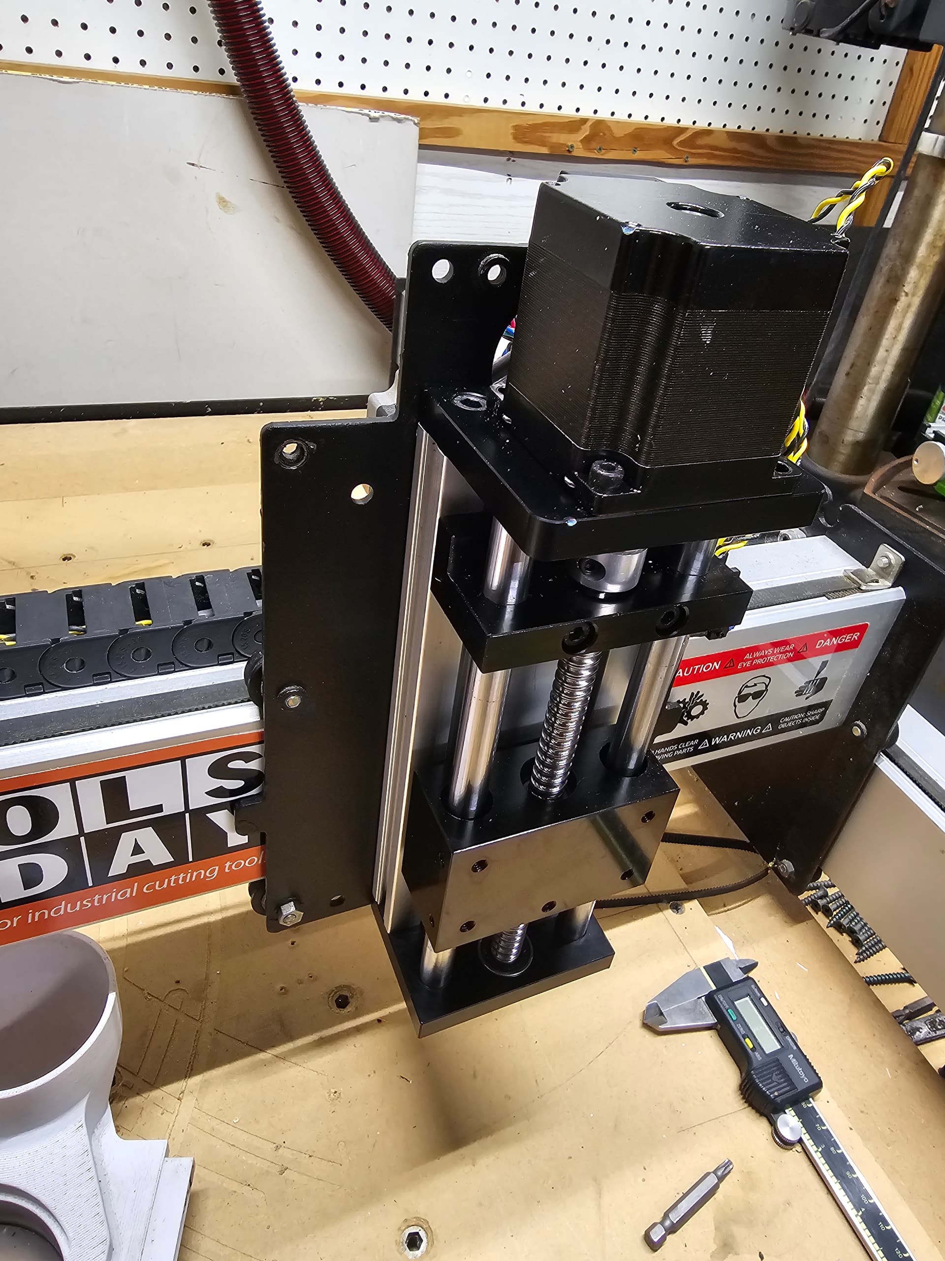
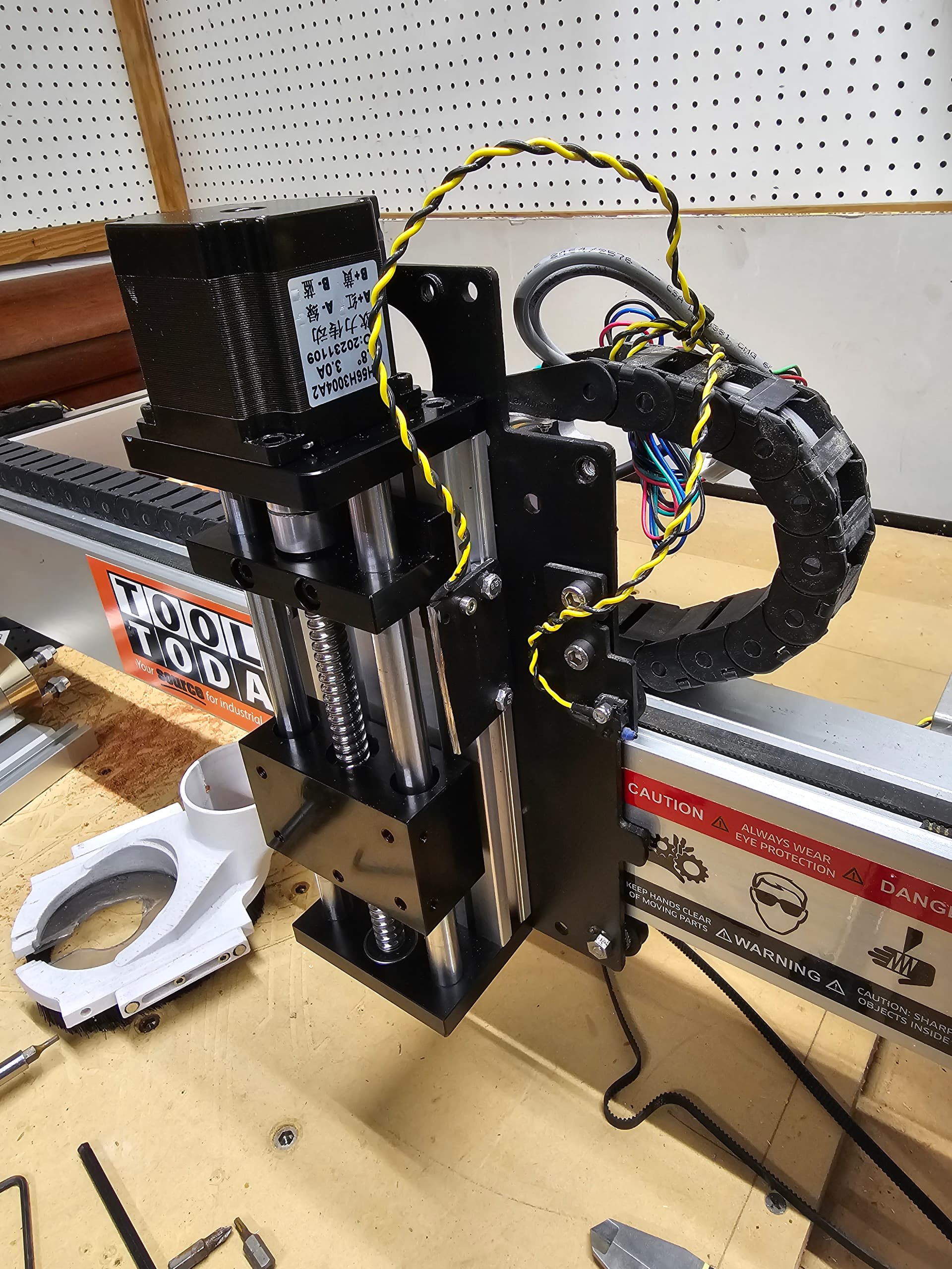
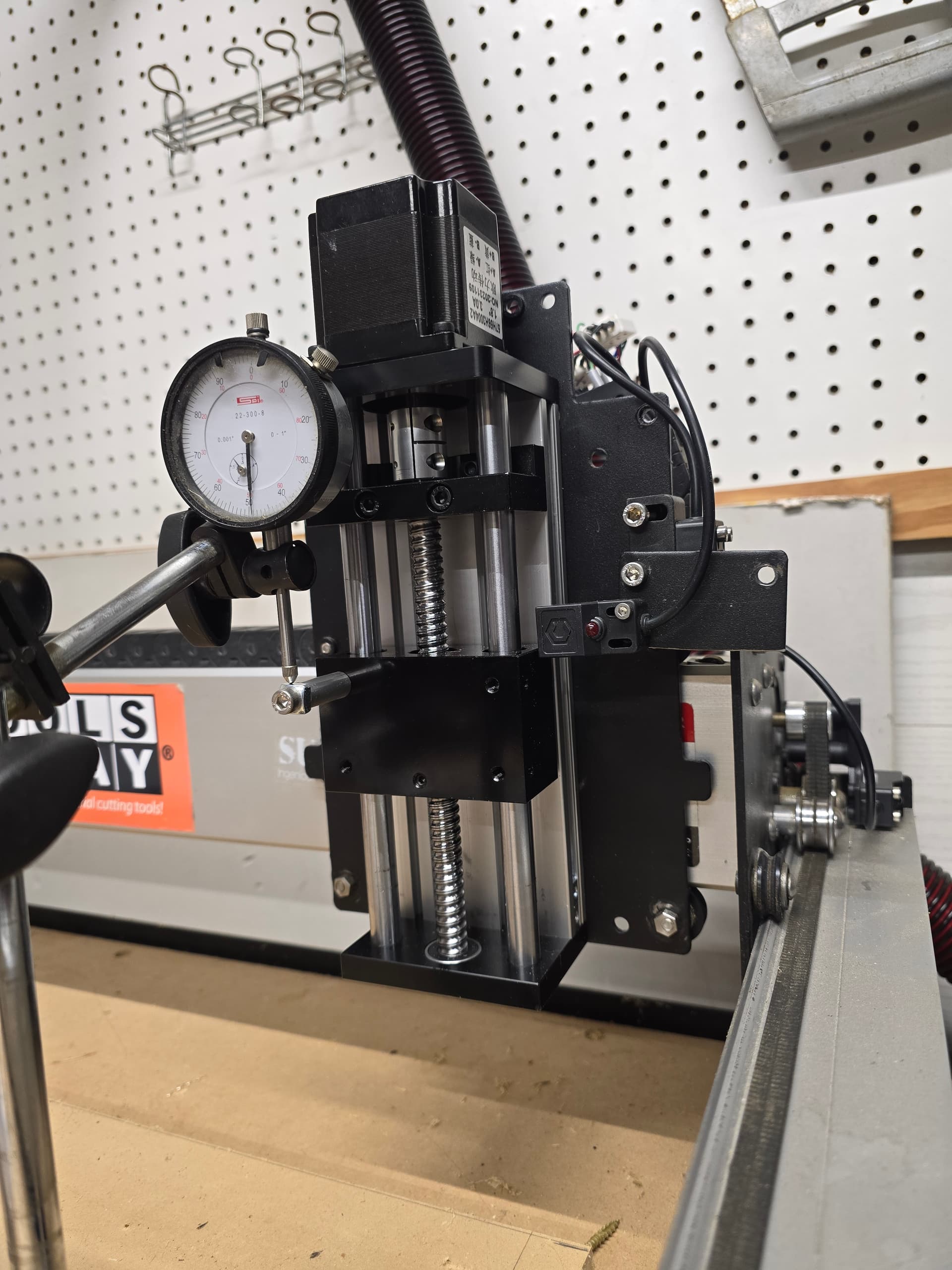
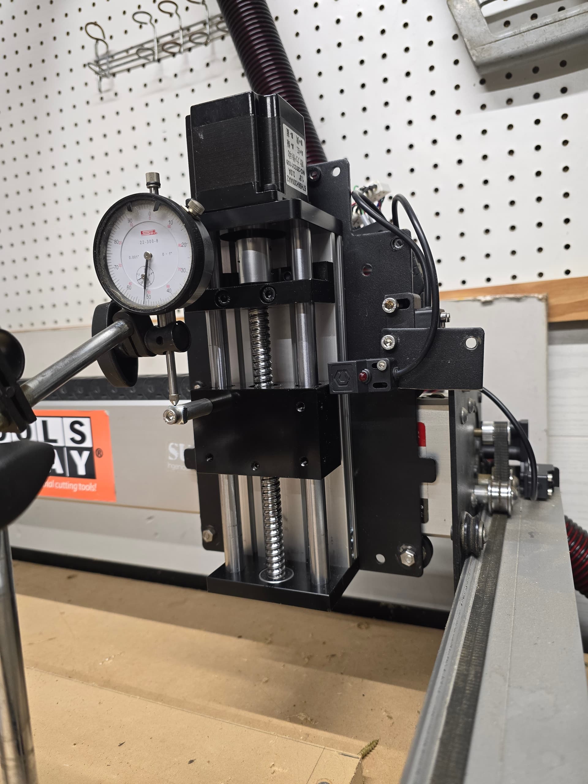
I finally got back to this mothballed project. A while back I decided to upgrade my punny DeWalt router to a spindle so it can handle long running projects. Letting the Dewalt router run for hours on end didn’t give me a warm and fuzzy feeling. Along that line of thought I decided to “upgrade” my Z axis to a ball screw to handle the extra weight of the spindle. I took a look at some folks builds and decided to build one myself.
This is outside of the scope of normal support, so please take the below as a statement from a fellow user, not a Carbide 3D support person.
To reverse the Z-axis stepper motor you have to toggle a bit or rewire the motor — my inclination would be to rewire if that is an option — just swap any pair of wires.
To do it in software, you need to change things in Grbl. See:
you need to set $3 — this is either set to 6 (SO3 w/ belt-drive Z-axis) or 2 (SO3 w/ Z-Plus or HDZ), and you need to add or subtract 4 (plus or minus 1 reverses X, plus or minus 2 reverses Y, plus or minus 4 reverses Z).
To calculate the number of steps/mm for the #102 Z-axis steps/mm setting you need to know a couple of things:
no. of microsteps — for a Carbide 3D board, that is 8
whether the motor is 1.8 degrees per step (200 steps / rev.) or 0.9 degrees (400 steps / rev.)
how much the screw advances per revolution — 4mm
so we need to do the math to get to the # of steps/mm to advance 1mm. There’s a Grblcalc app for Java at: AtomSoftTech (Jason Lopez) · GitHub
The Z-Plus leadscrew uses 200 steps/mm, while the HDZ uses 320 — I’d just set it to 200 steps/mm, jog down to the baseplate, set the origin there, jog up by 25, 50, or 100mm (whatever the movement will allow) and calibrate per:
This is outside of the scope of normal support, so please take the below as a statement from a fellow user, not a Carbide 3D support person.
Yup. That’s why I placed it in the unsupported section.
Thanks for the information. I’m heading back out to the shop to see if I can apply this to the abomination I hath wrought. I shall report back with news.
Was able to successfully get the direction corrected. Fighting with serial terminal software to connect to the port in order to write the correct steps for 1mm travel. I’ll play with it tomorrow.
It’s off about 2 thou. A bit more refinement and I’m sure it can get it dead nuts.
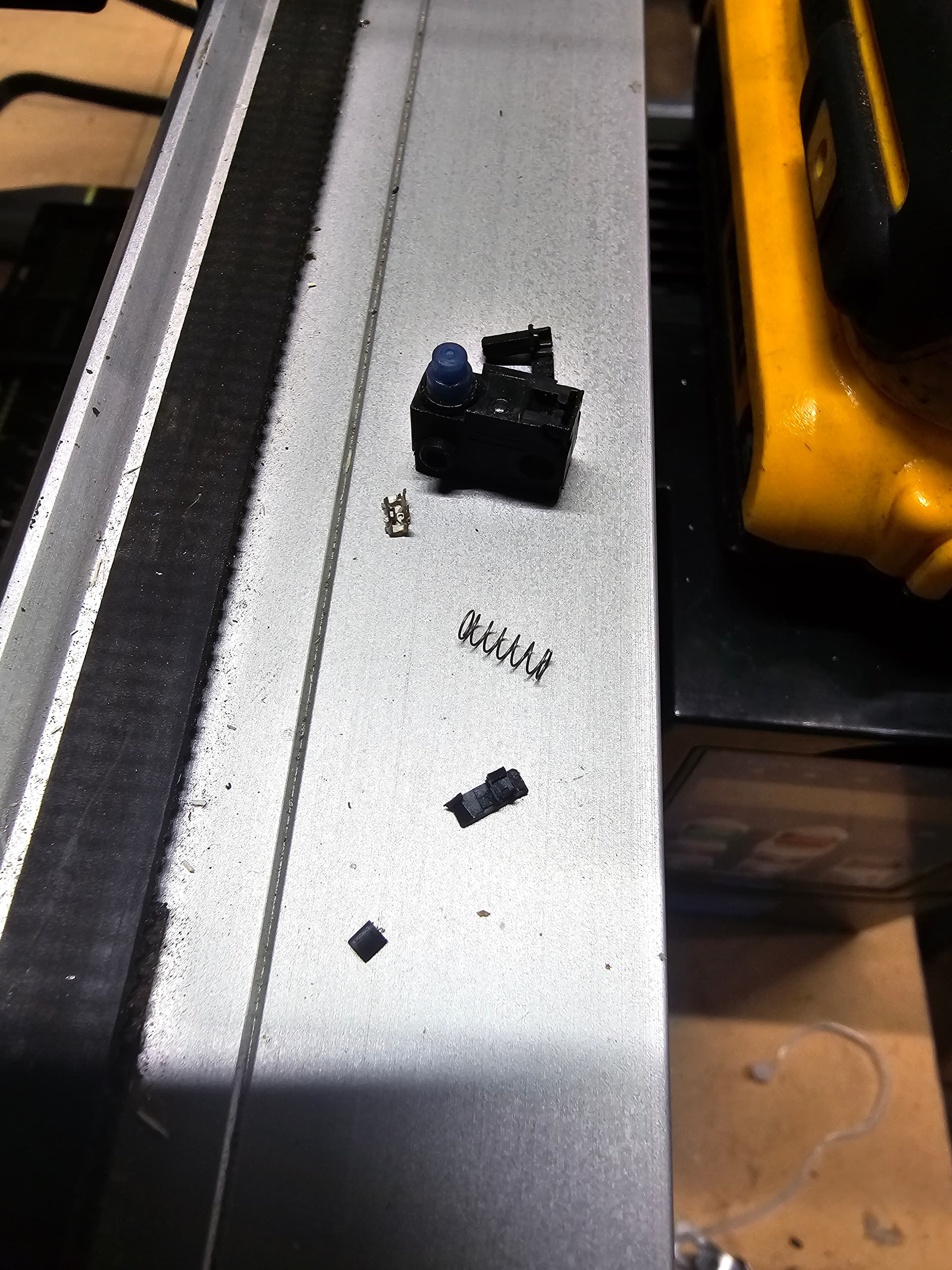
I figured out why it crushed the Z switch. While I was screwing around I forgot I put the stepper wiring back to what it was before I reversed it. So the system thought it was moving away from stop, where infact it was moving towards it. Oops.