Hi, I’m setting up a 5 Pro with a 80mm spindle.
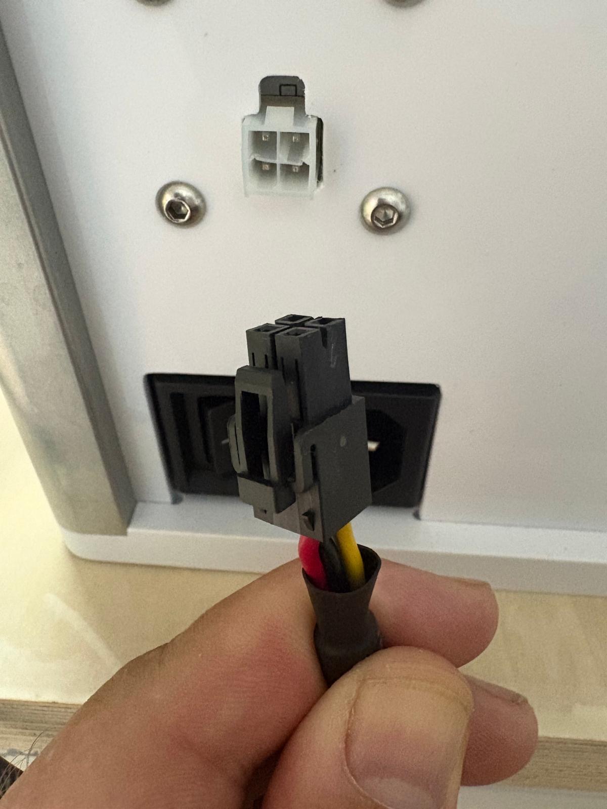
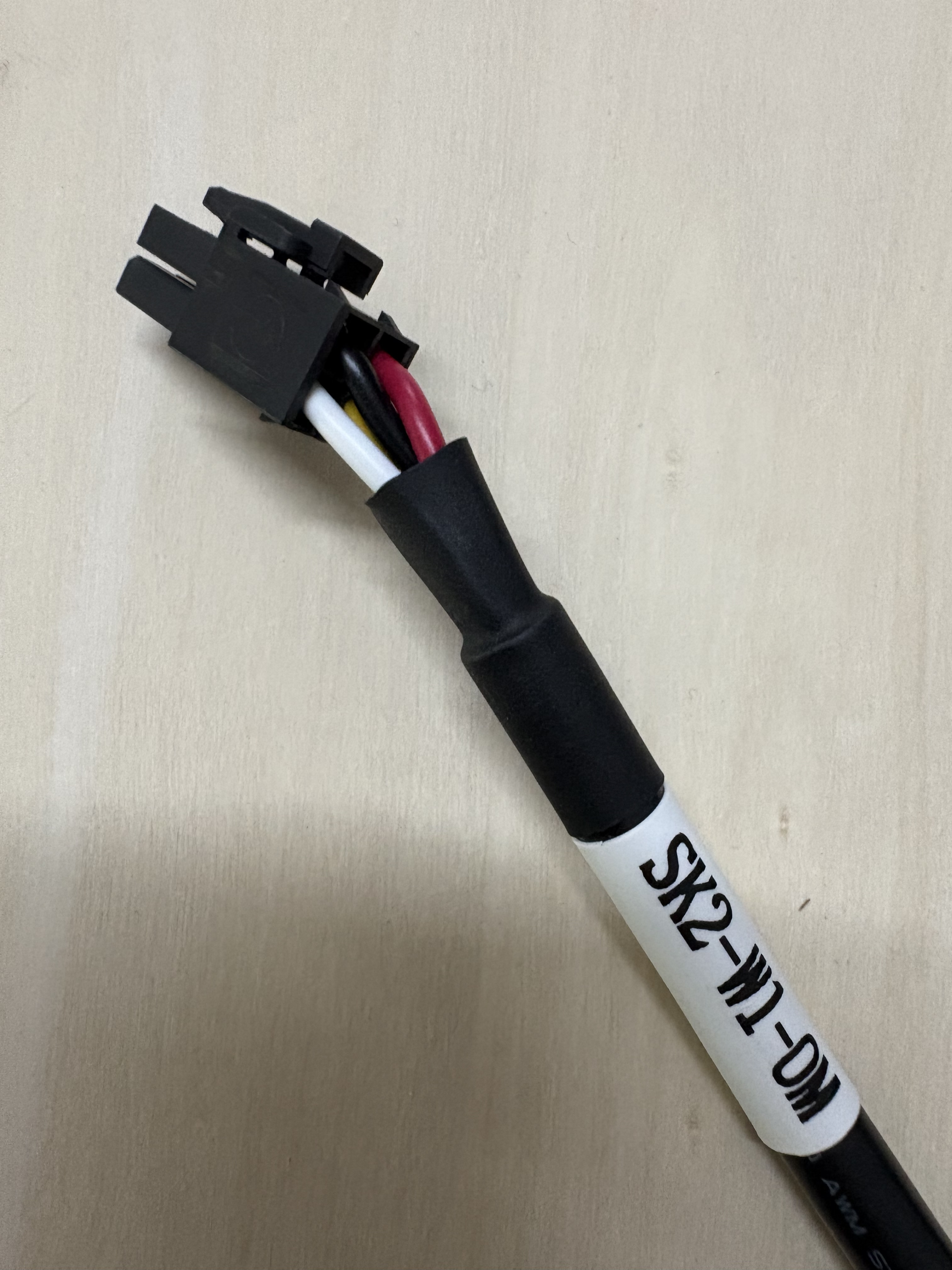
I can’t seem to get the cable (SK2-W1-OM) in between the spindle and VFD. You can see that the connector only inserts a few mm, but the VFD needs a “deeper cut”.
Any ideas?
Thanks!
Hi, I’m setting up a 5 Pro with a 80mm spindle.
I can’t seem to get the cable (SK2-W1-OM) in between the spindle and VFD. You can see that the connector only inserts a few mm, but the VFD needs a “deeper cut”.
Any ideas?
Thanks!
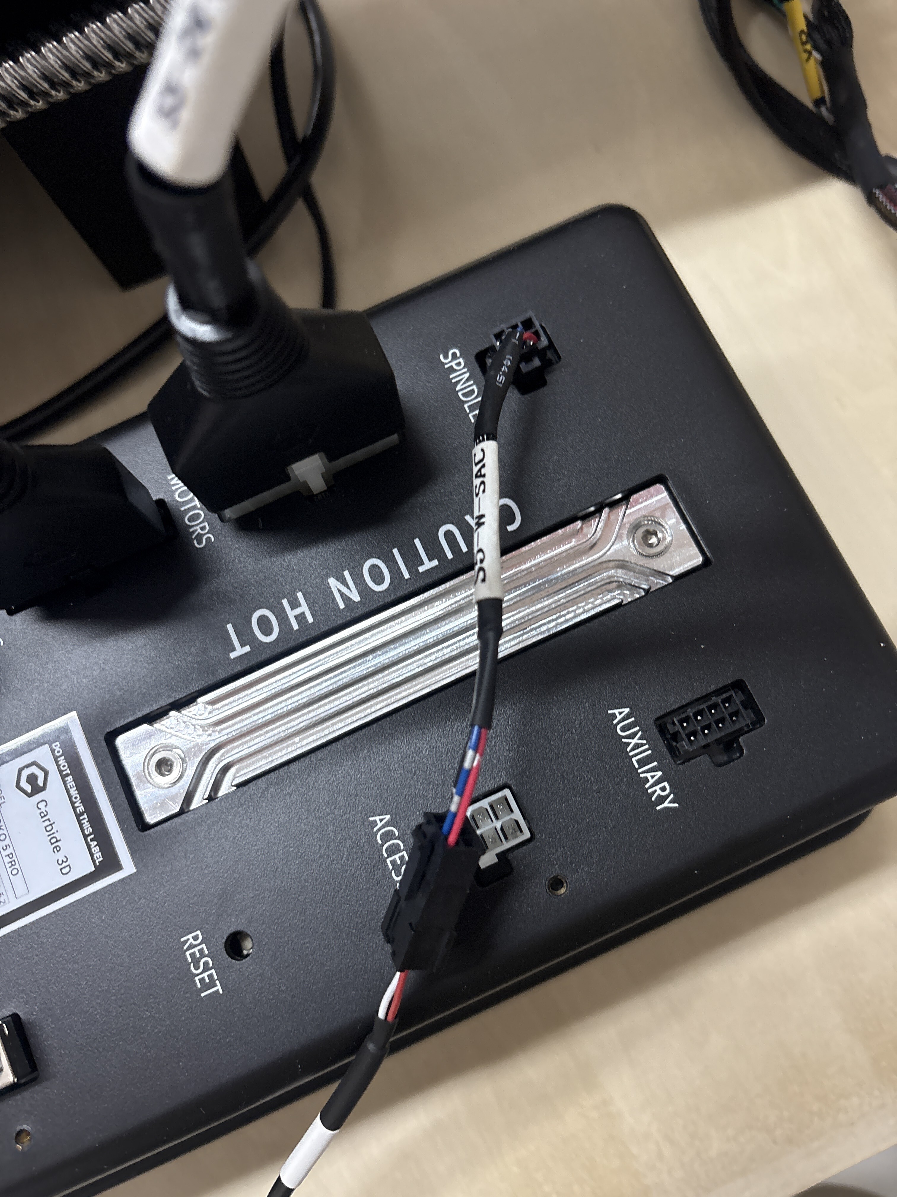
There should be a small adapter cable:
If you don’t have it, let us know at support@carbide3d.com and we’ll work out how to get it to you.
Thank you for the answer.
As far as I can see (videos etc) there is no adapter between the VFD and spindle. the adapter is between the VFD and the controller right? That I have. The issue is something else.
Thank you!
Obviously, I need to learn to count.
The matching instruction from:
seems to be:
- Plug the 4-pin spindle power cable into the connector on the right side of the VFD Control Unit.
Someone with greater familiarity with the VFD connections should be able to advise presently if that doesn’t make things clear.
Hm…. Maybe I’ll just take a chance and make the cut on the connector so it fits. I mean the cable is the correct one. I’ll just need to figure out the right polarity for it all, to be sure.
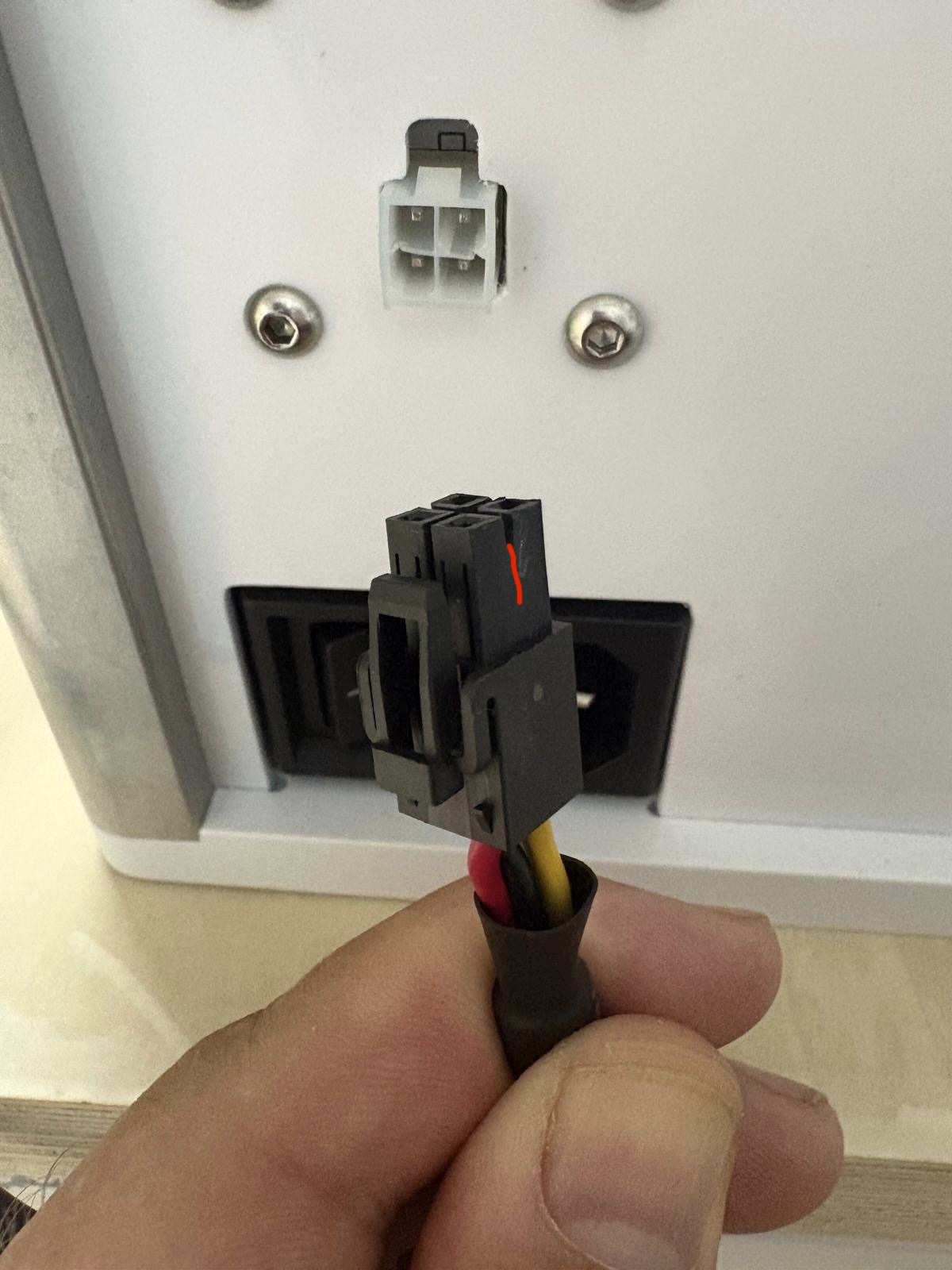
The other side is fine. See red line.
It’s such an anticlimax on the last 10 yards.
It may be an artifact of the photo, but the receptacle on the VFD looks like the center bar is distorted. That may be preventing the plug from properly inserting.
John
Hi John, thanks for the tip. Just checked and that is because I tried to push it in a bit too hard probably.
One side has the right length open but not the other.
It looks like the top right and lower left sockets on the VFD side take slightly rounded male counterparts. Does that black plug have slightly rounded corners in those positions to fit those sockets?
Maybe mold flash? On a worn or not-well-maintained injection mold that would be an early place for flash–a skinny shutoff area…
Mold flash I would guess. Here is the other side of the cable, I’m guessing both sides should be equal.
Yes, the slots in both directions should go down to the surface of the main connector housing. I verified that on my own VFD cable using the back of an Xacto blade as a feeler gauge (it was the first thing I was able to grab…)
This topic was automatically closed 30 days after the last reply. New replies are no longer allowed.