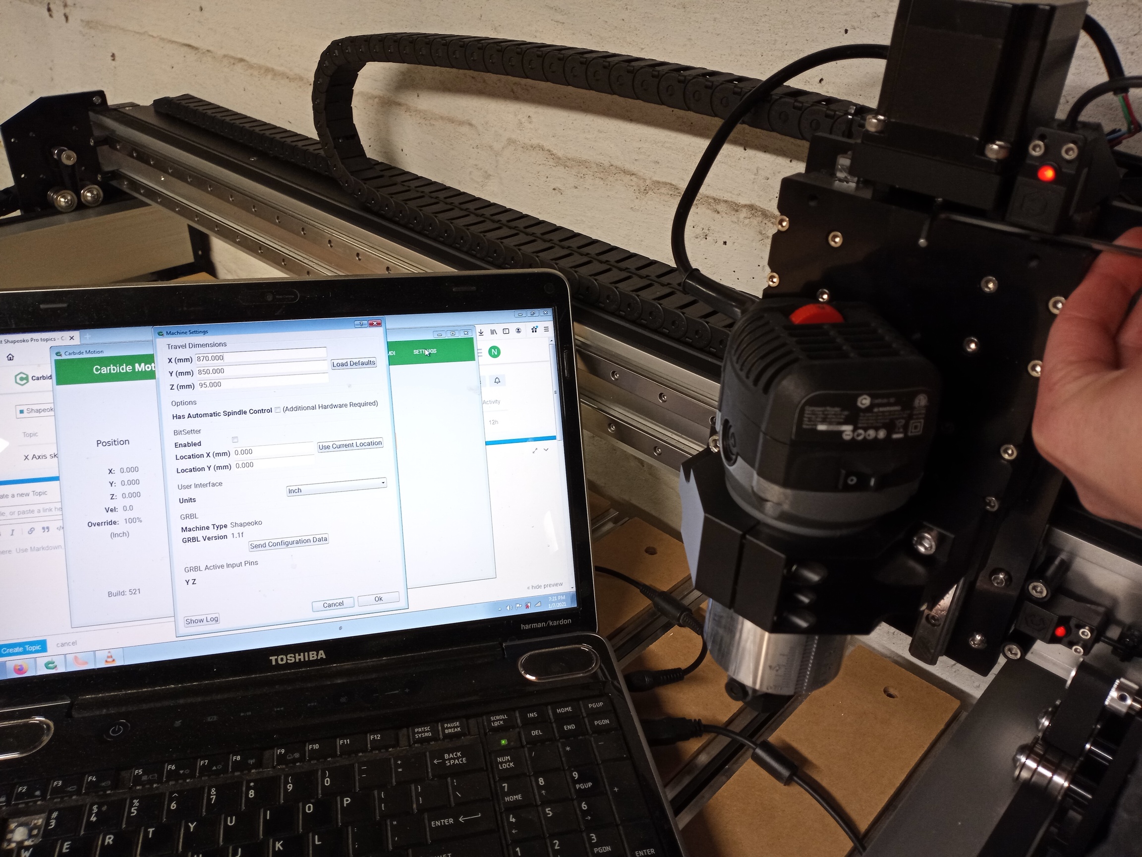
I just finished putting my PRO XXL together, and seem to be having an issue with the inductive sensor on the X axis. The light on the sensor lights correctly but I get no notification in the settings, and homing fails.
I dont have a pro but upgraded my XXL to proximity switches. My X switch did the same thing because the instructions tell you to mount it up as high as possible. When I moved the switch down some it worked fine. I think the Pro and XXL are similar in that the right plate is similar.
So move your carriage all the way over and adjust the switch until it registers in the CM screen.
Could be a faulty/flaky contact at the controller side of the X switch wire in the connector housing. The fact that the prox switch LED works proves that GND and 5V are there, but the third signal may be broken somewhere along the way.
I have never seen a Shapeoko Pro controller board up close yet, but I guess it has the blue LEDs that light up when one of the switches is triggered ? If so, if nothing lights up on the board when the X prox switch red LED turns on (while it is the case for Z and Y), you’ll know it is that (the signal not quite getting all the way to the controller). If it is that, inspect the connector visually for a loose contact ?
They just installed a plastic bracket behind the sensor on the x. But when they screwed it in, they didn’t push it really hard towards the router.
Unscrew the bolts 1/2 turn and push the switch really hard towards the router and retighten.
Edit : when reading through your problem again you are getting the light when the gantry makes its way to the x axis, so that’s different from my solve
I checked on the board and the LED status lights never turn on for the X axis. I was going to try plug the input into different sockets on the board, but the pin arrangements are different for each. I realized that the connectors on the sensors for the Z and X axis were the same, so I took the Z sensor off and plugged it into the X sensor wiring. The board and Carbide Motion now detected the X axis, so I think the X sensor is just faulty. I’ll have to contact support for this.
I talked to a support person, and he said the wires that plug into the board are done in such fashion that even if you plug them into the wrong slot the hardware should still recognize them as the correct sensor/switch.
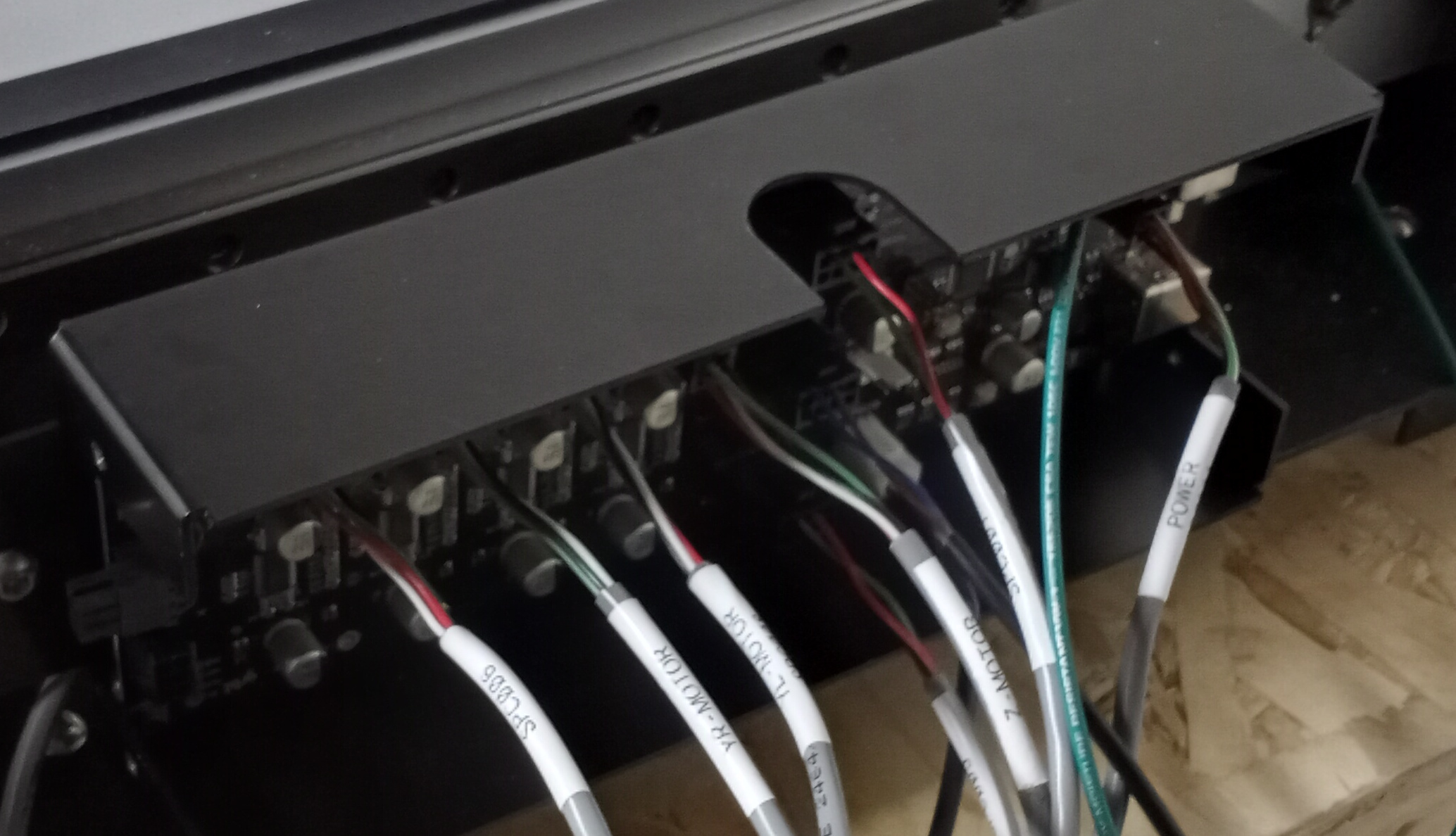
On the Pro the control board has three inputs for the limit sensors, right below the notch in the picture. (Ignore the board being installed in the box upsidedown) They are 8-pin connectors, but only three pins are used in each. My guess is they probably share power and each use a different pin location for the signal. The circuitry can read the signal on every pin in each plug, and ignore any pins with no signal. Nothing magical about it.
I think misread your post as they said you could plug the connectors in any input and the controller would identify XY and Z.
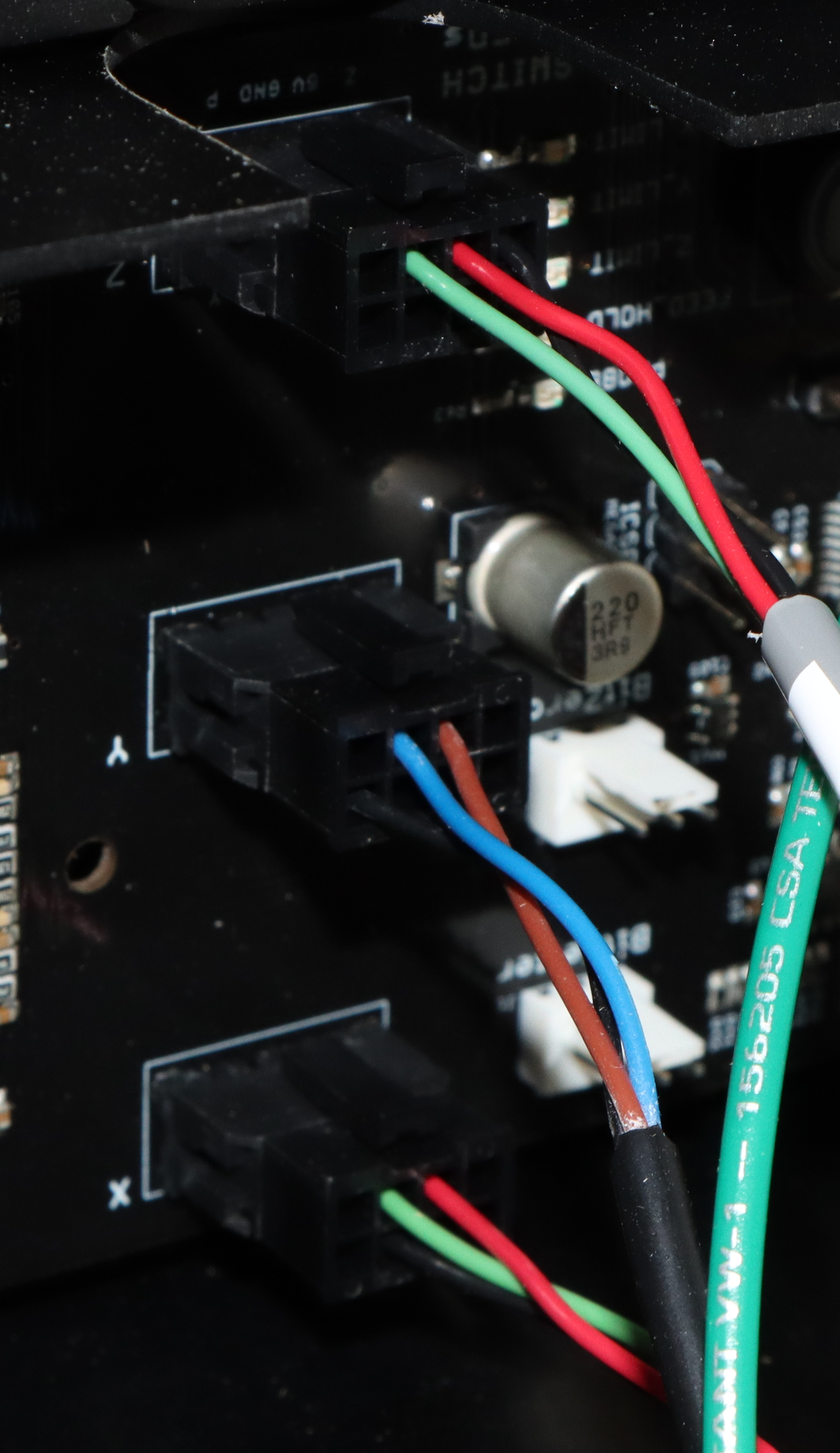
Anyway, the proximity sensors have three wires: +5v, ground, and a signal. If those are mixed up, the switch won’t be read by the controller. That’s why I asked if the wire order is different.
Hmm, that might be a possibility, but I wouldn’t know what the correct wiring should be. I’d guess that they are right though, as the status LED functions, and if the power and data pins weren’t correct I wouldn’t expect that to be the case.
Depends on the internal circuitry, but I wouldn’t ask if it hadn’t been an issue raised here before. As @Julien mentioned, another one we’ve seen several times is a bad crimp or loose wire at the connector.
It could be a bad wire on the sensor end, unfortunately I wouldn’t know how to try and check that out. Swapping the sensor with the Z sensor let’s me know that it’s nothing in the drag chain wiring or on the board as the system reports a signal correctly that way.
Maybe post a close-up pic of the connector & color wires, someone else with a Pro can compare where the color wires are in the housing on theirs ?
Have you contacted support? they should be able to confirm the wiring at the connector is ok or not.
The three signals being GND, 5V and Signal, and signal going to GND when the prox is triggered, you could in theory use a voltmeter to figure out which is which, but that sounds like a lot of complications (no access to the signal while everything is connected), and risks of doing something silly and damaging the board, hence my two recommendations above.