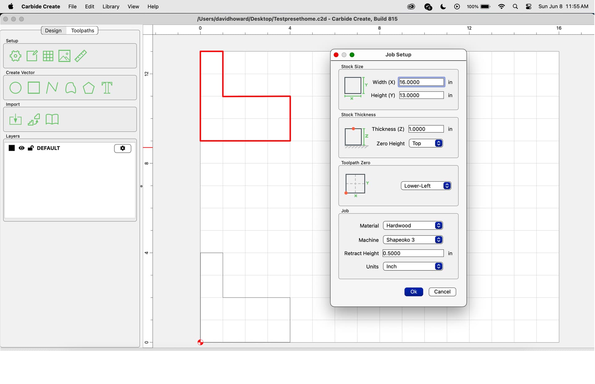
As you can see on the image I set the stock (work area) Width (X), 16 inches. and Height (Y), 13 inches. X axis being across or left to right of the machine work area and Y axis being front to back of the machine work area.
On the Zero Toolpath the X axis is showing front to back and Y axis showing left to right, the exact opposite of the stock. I use lower left as the home position or Zero.
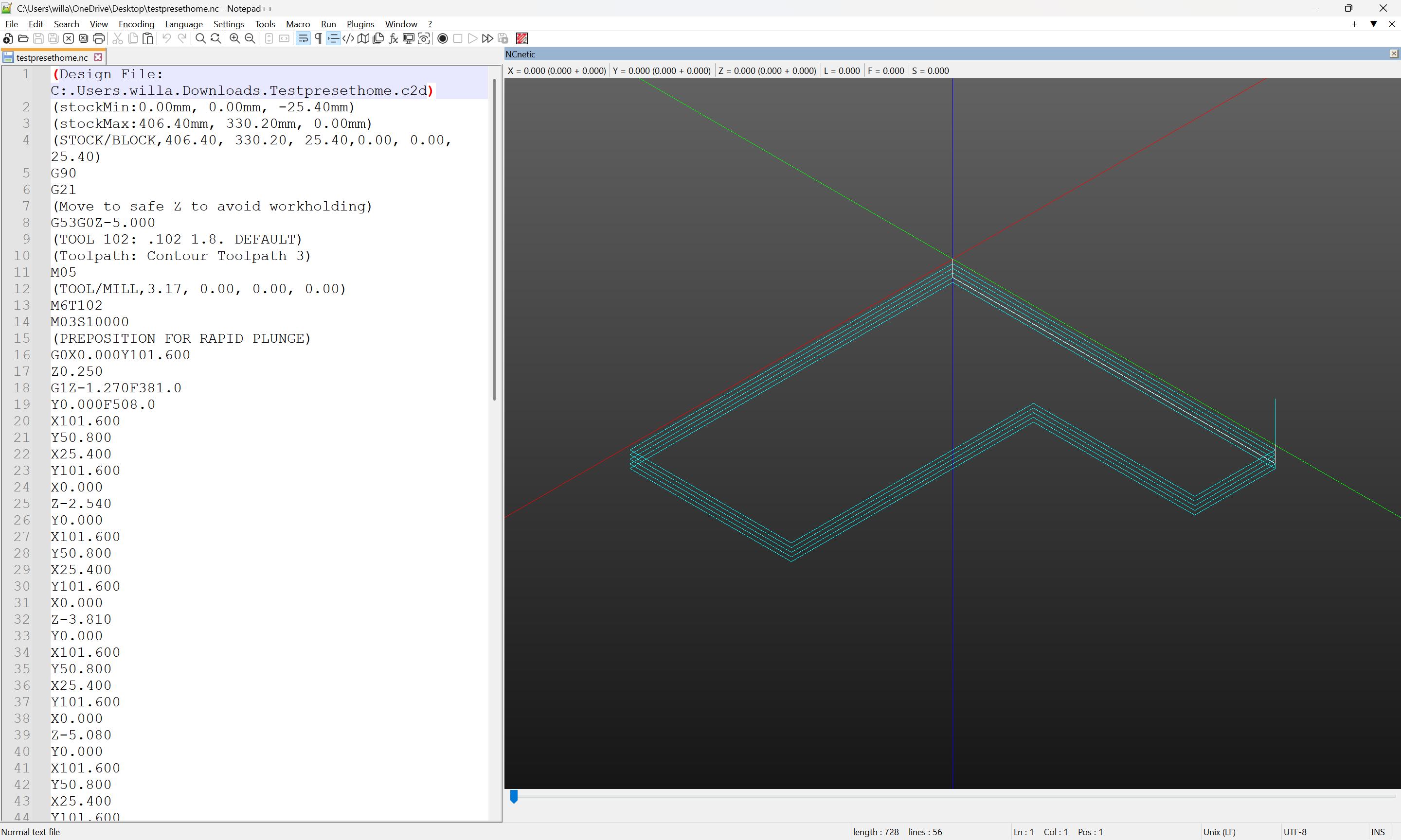
So I did this simple file to see what the machine would do, when I simply load and let it use the X-Y as indicated in the file… The area with a red line is what the machine actually went to cut. I didn’t have any stock loaded and so nothing was actually cut.
The problem is the X Y axis in the Toolpath Zero is opposite of the stock and the Zero lower left of work are is actually upper left. Why is it the opposite and why is lower left actually upper left?
I always set my zero use the jog function which tells the machine where Zero is, but I wanted to see what it considered lower left to be? And it’s completely wrong.
It no, upload your file, and post a photo showing your machine at zero relative to the stock (or a specified offset) and screengrabs showing what Carbide Motion shows for both Position and Machine Position (click to toggle).
Your first link is about the basic setting of Zero using Carbide Motions Jogging function and this is how I set Zero for every job, I use this process for every job.
My post is about using the zero function in Carbide Create, where I have set the toolpath to Lower Left, exactly as described in the second link you posted of how to set zero in carbide create.
The problem is if I use the toolpath zero of lower left embedded in the file with carbide create, load the file into carbide motion and do not use the Carbide Motion function to manually set Zero and simply use the Zero setting indicated in the Carbide Create file it goes to the top left.
And the second issue is carbide create having the stock X-Y orientation different than Tootpath Zero…
I will continue to use Carbide Motion to set my Zero (as I always do), but I am still questioning the Toolpath Zero in Carbide Create and why lower left is not lower left.
My normal process is to launch Carbide Motion, initialize the CNC, then use the carbide motion jogging function to set the exact zero, then load the job and run it…,no problem. This entire post is about using the carbide create toolpath zero function, of lower left then loading the file in Carbide Motion and run it and not set the zero in C. Motion use the zero set in C. Create…
For clarity… In CC you are telling the software where you plan to set zero on the machine.
In CM, you have to set the zero in the same relative position you used in CC.
There is nothing in the G-code to tell the machine where to set zero. You have to do it yourself.