XXL Aluminum Baseboard

I seem to be following right behind you in the Y-plate flipping department. I’m running an XL, and I’ve been doing spindle+laser projects recently. The laser is offset -87.2mm from the spindle in the Y axis, so I only get something like 180mm of prime usable Y (on the bed and reachable with both the spindle and the laser). That’s too little for some of my planned upcoming projects, making them unnecessarily inconvenient, so it seems now’s the time to get shifty in Y.

When I was doing another walkthrough of my planned procedures this morning, the only outstanding item I noted was the Y-axis limit switch. With the plates swapped, the limit switch mounting is by the forward edge of the now-right Y plate. I figure mounting it there and attaching a block to the rail to provide the necessary offset should be a cromulent solution. (The line conveniently included in the extrusion makes it pretty clear that there shouldn’t be an interference.) I’m just curious about what you did (or are planning to do).

I haven’t worked on them since my last post. I hate it when life gets in the way of the fun stuff. :slight_smile: I was going to do something similar to what @ItsDan did - use aluminum spacers or a folded aluminum bracket to put the limit switch in the correct location. I have the Precision Limit Switch set from @Luke, so the mounting will be slightly different than the C3D limit switch set.

Well, there, I’ve gone and done it.

  • I ground down one side of the 4th spacer in each motor on my belt sander. (It was quite easy, and I get to keep the four-legged mounting.)
  • I did go with the block on Y (with the stock switch mounted on the front edge of the now-right plate).
  • I added a limit switch spacer on X, since things hit the various nuts that are now in front of the extrusion.
  • I altered my soft limit on X (accounting for the nuts and such on both sides), and conveniently, my laser mount now clears the front plate.
  • I flipped the Y bit on $3 (Direction port invert, mask), changing $3 from 6 to 4.

And after carefully checking everything (movement, limit switches, soft limits) in UGS, I’m going to call it a success.

Oh, and thanks for the drill guide. I printed it while I was disassembing everything, and it made the new holes quite convenient.

4 Likes

Hallelujah!

I’ve been away from here for months as my shop is just unbearable in winter. With spring in the air I poked my nose back here in the Carbide Community to find this little gem. I am ordering straight away for my XXL!

I had attempted to champion the Shapeoko Users Group XXL Al base buy many months ago but literally little to no takers. The moral of the story, good things come to those who wait. Thanks for posting this thread!

1 Like

Just ordered…

\ 40x40 Ohio Diesel Parts LLC


Order Summary
\ 100x100 Shapeoko XXL Fixture Table Custom Metal Aluminum Plates 600+ Mounting Points

1 Like

That’s a great idea. I didn’t think about grinding away the spacer. I am definitely going to do that. I just need to order a few more. I ended up using those two elsewhere.

I’m glad the drill guide worked out for you. I now have all of the mechanical parts assembled (minus the spindle) and now I just need to work on the routing of the wiring. I ordered some drag chain that will hold all of the wiring, but it will not be here for 2-3 weeks. It has an internal cross section of 1.5in x 2.0in so I can run everything (VFD wire, coolant tubing to and from spindle, and all of the stepper motor and end stop wires).

3 Likes

Modeled the 3D printed bracket for holding the drag chain.

Then I 3D Printed it with 1 perimeter and 10% infill just to check fit.

Printed it at 1 perimeter and 10% infill just to check fit.

Looks good to me. Other than adding some fillets here and there, I’d say it’s done. McMaster-Carr order already placed for the fasteners. The large opening around the fasteners are for 3/8" OD spacers. The 3D printed part is 0.20" thick and the spacers (0.253"-ish by 0.0375") by 0.1875" long are in case I crush the 3D printed part - then the spacers will take the stress to ensure the end bracket is secure. I ordered longer fasteners as well for those two fastener holes.

I’ll paste the files once all three brackets are finished in case anyone else wants to order the ridiculously large drag chains - which to be honest - are growing on me. :slight_smile:

5 Likes

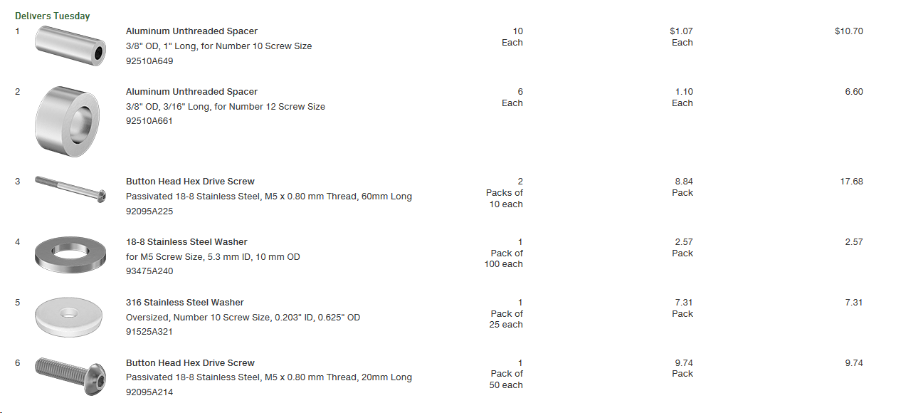
Here’s the parts list:

You can ignore the 1" spacer - that is for something else.

2 Likes

What kind of printer did you use?

Prusa i3 Mk3 upgraded to Mk3s. Actually, it’s the first print after upgrading the hot end to the Mk3s hotend parts.

I cannot recommend this printer enough. With a Raspberry Pi 3B and Octoprint, it is the best setup ever. Yes, I am biased, but after having a cheap $200 acrylic Chinese printer, this is the easiest and most low maintenance printer ever.

EDIT: Full disclosure: I owned a MK2 and Mk2s and two Mk3’s and the MMU 1.0 and the MU 2.0. I sold the two Mk2’s.

Okay thank you, I’ve been thinking…

@MadHatter, like your design, looking forward to your sharing (hopefully) the Fusion file. I’ll need to make mine a bit deeper in Y to clear my linear support hardware.

I’ve had a fat DC sitting in my spares drawer along with a JTech laser for the past year. Just today got the laser reconnected. The new magnetic mount seems like a great idea. Just need to add some connectors for the laser/fan at the juncture with the DC to make it useful.

I went high with my temporary DC mount. Funky but practical.

Just about ready to reverse the X plates. Then comes the new DC setup

Edit. @cgallery, can’t go wrong with the PRUSA Mk3s. My first and only printer.

2 Likes

@Griff, I am using SolidWorks, but I just looked it up and apparently Fusion 360 can import SolidWorks .sldprt and .sldasm models.

Here is the folder where you can get them. I’ll save the first one as a .sldprt and see if you can open and manipulate it. If not, we’ll find a file format that you can easily modify.

1 Like

Got it, thanks so much.
That will work fine I believe.

1 Like

Spent a few hours working on the next part of the drag chain brackets. The transition to the gantry was just going to be too big for one piece, so I made it quite a few pieces. They are held together with #4-40 screws from McMaster-Carr - mainly because I have a few boxes of them.

There is one bracket (magenta) that sits on the two 1" long x 3/8" OD aluminum stepper motor spacers, and has a screw that pins the bracket to the spacer so it can’t move.

The brown bracket has adjustable slots so that it can properly support the curved bracket at the right height regardless of the stepper motor height (due to needing to tighten the toothed belt).

Also, the green curved bracket has adjustment slots in case things just don’t line up like they should.

And if I can do it right, here is a screen grab video.

1 Like

Pretty sweet design. THIS sort of thing is why I bought the PRUSA Mk3! (now mk3s)

I’m going to continue my education in Fusion360 and see what I can come up with using your models as inspiration.

Thanks for posting.

1 Like

Here’s a quick update. I printed the stepper motor bracket and brace. Other than some small tweaks, they fit as designed. Once the rest of the parts are printed I’ll find out if they are going to work.

2 Likes

Well, all of the 3D printed parts fit together just fine, but I missed the drag chain minimum bend radius by an inch. Sooooo, I am going to move the rear drag chain bracket down so that the drag chain is level with the bottom of the waste board. That will also give the Belkin VFD wire a lot larger bend radius as well.

That means I am going to have to move the gantry bracket down to the bottom of the extrusion as well and have the bracket on the Z-axis a little bit higher I originally planned.

No worries, I’ll get it to work.

4 Likes

Looking real good!

I love seeing 3D printed functional parts. It seems like a lot of what I see on the 3D printer collections is more artsy these days (I’m guilty of printing some Yoda heads and octogoats myself). It’s really nice to see tools making tools!

Dan

2 Likes

This topic was automatically closed 30 days after the last reply. New replies are no longer allowed.

Continued at: