My Shapeoko 3 XXL should arrive in a couple days and I’ve been reading about issues with the MDF base sagging. I’m thinking about getting the wasteboard made out of 1/2" aluminum before I assemble to provide a more rigid base. I still plan on installing a threaded MDF waste board on top of it.
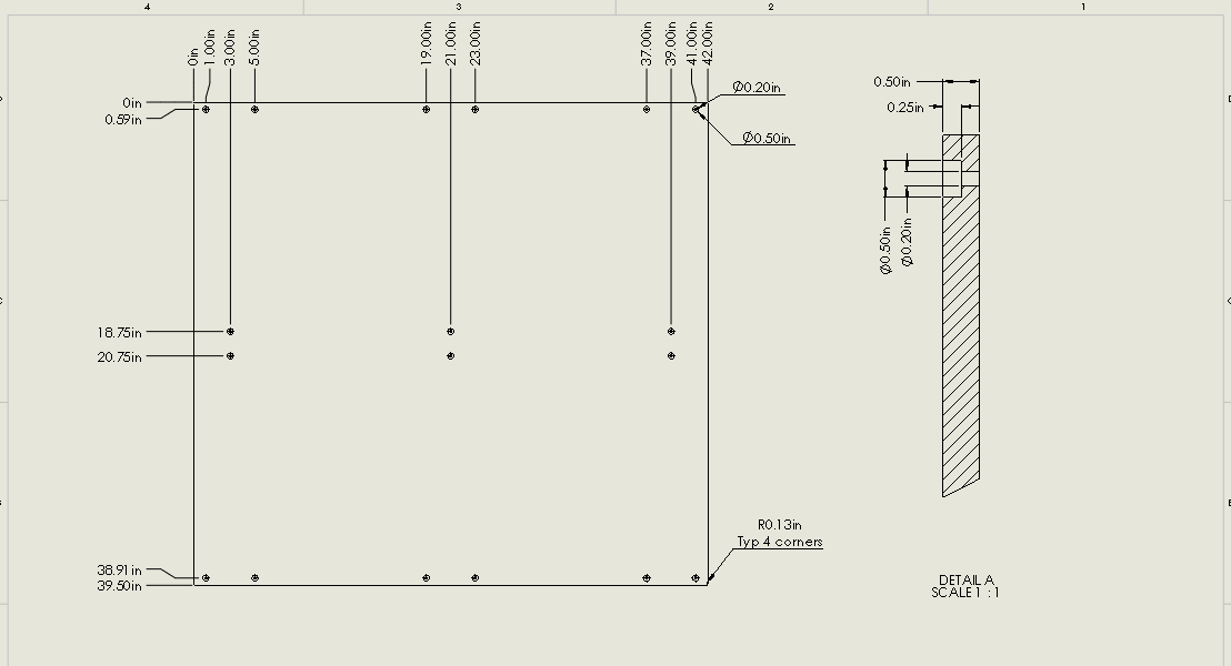
I believe I found the drawing for the stock mdf board is two pieces. Can any one confirm if my drawing would work for a 1 piece base?
Well, if you are worried about the exact hole locations, you can slightly oversize the holes and the counterbore slightly larger than the original MDF board so you can make sure you have enough room for squaring it up. Just use larger head fasteners or a thick washer with a tight ID. McMaster-Carr sells washers with tight tolerances.
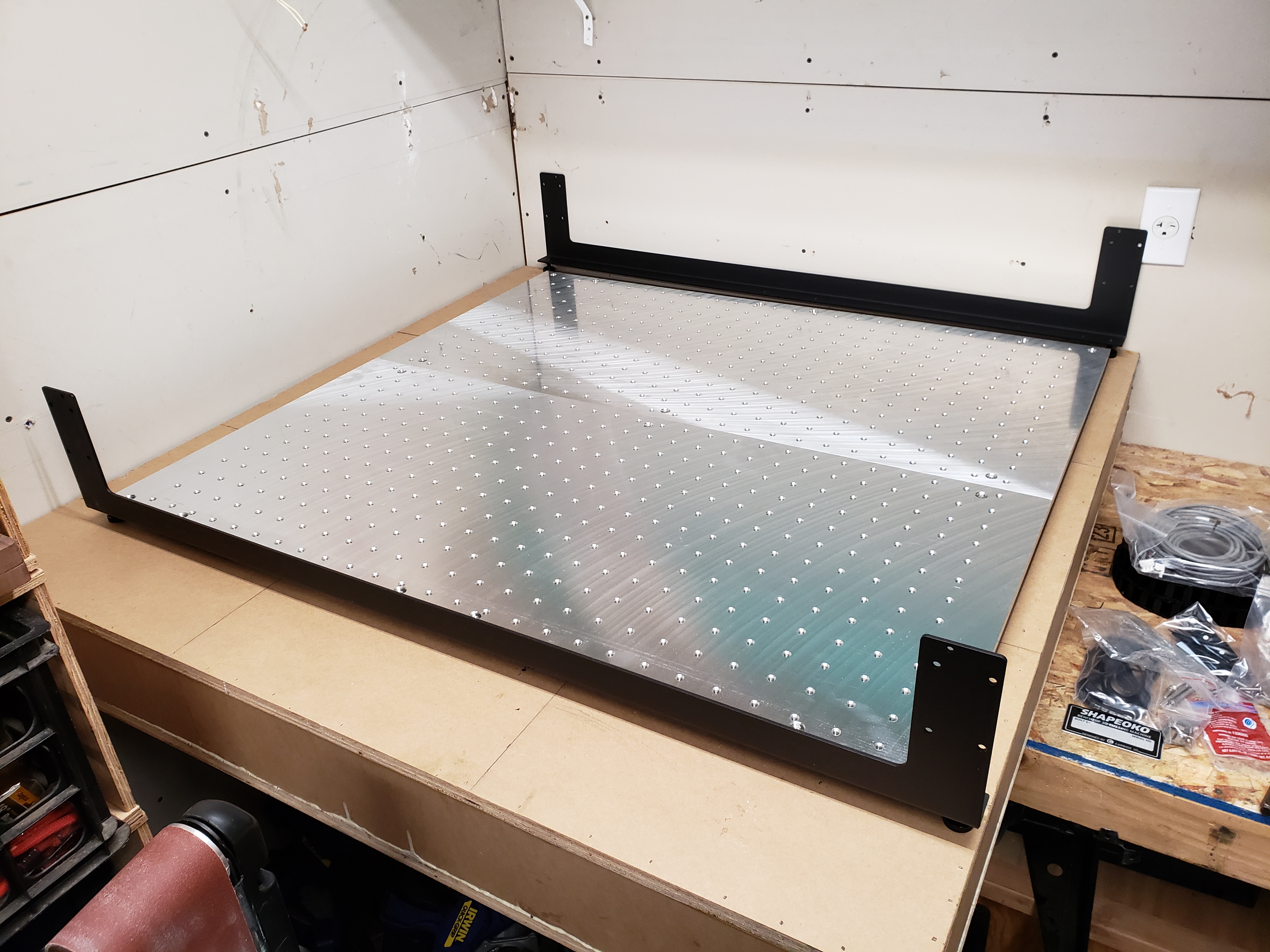
Also, just in case you haven’t seen the other thread, Ohio Diesel Parts just started selling a 2 piece XXL aluminum base. They are making them with 5/16-18 threaded holes at 1.5in spacing. I had mine drilled and tapped for 1/4-20 since I had ~$300 in stainless steel fasteners and clamps already from my original SO3.
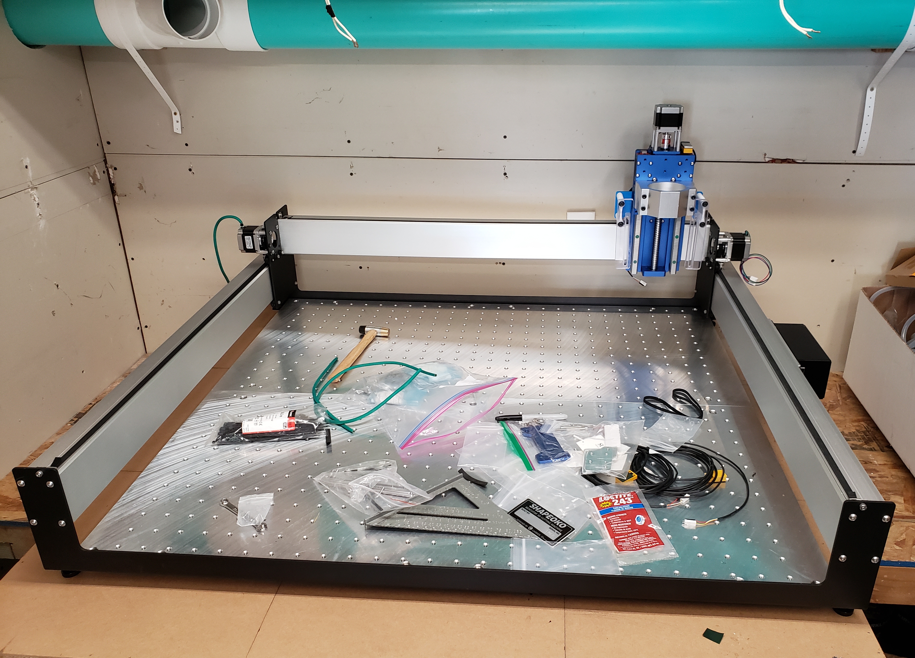
I received the base plates just the other day and I am working on assembling my XXL after having it sitting in a box for 3.5 years (long story - lack of space).
I think it is going to be a great machine after I get the Y gantry plates flipped (there is not a lot of info, but I will probably make a post to show the process and what needs to be done to make it work) to move the usable area to the back of the machine (since I am not interested in using the ability to have the spindle extend beyond the front of the machine) and get my HDZ installed with my 1.5KW spindle.
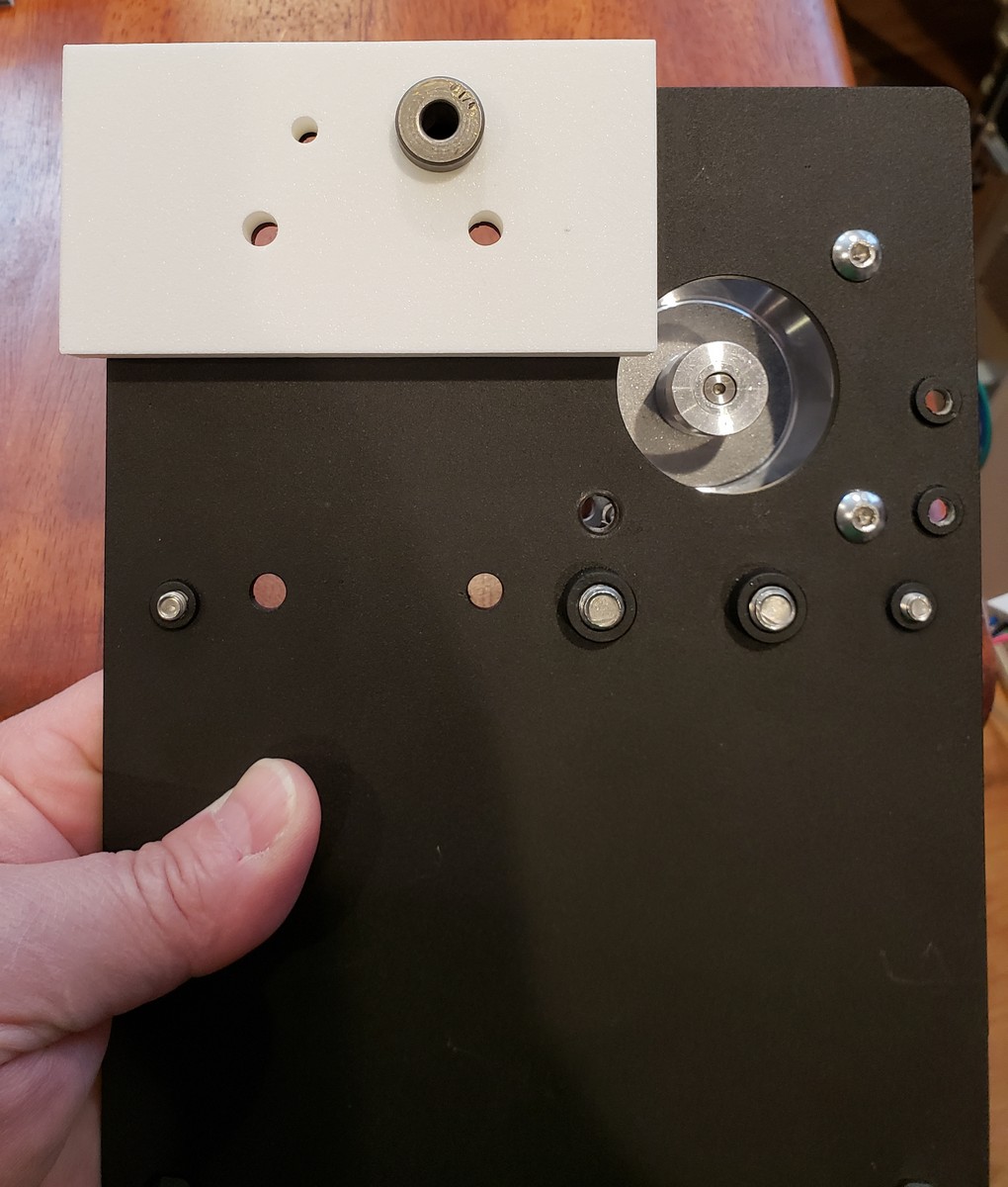
Well, I flipped the Y-carriage plates so that the motors are in front of the gantry now. Phil Thien did a pretty good write-up on it here so I am not going to re-hash it, but I did make and print a template for drilling the new belt clip. Here is the location of the two templates. The template is for making sure your printer printed it correctly. It is thin and has the correct sized holes in the correct locations (as best as I could get). The jig has a large hole where the new hole is to be drilled to that a drill bushing can be installed to guide the drill bit. They are in SolidWorks format, STL and STEP formats. This bushing is what I sized the hole for, since I had a bunch of them laying around. It is a bit bigger than needed, but I justified my impatience with the fact that the HDZ uses slightly wider V-wheels and I needed the clearance to keep the wheels from hitting the belt clip.
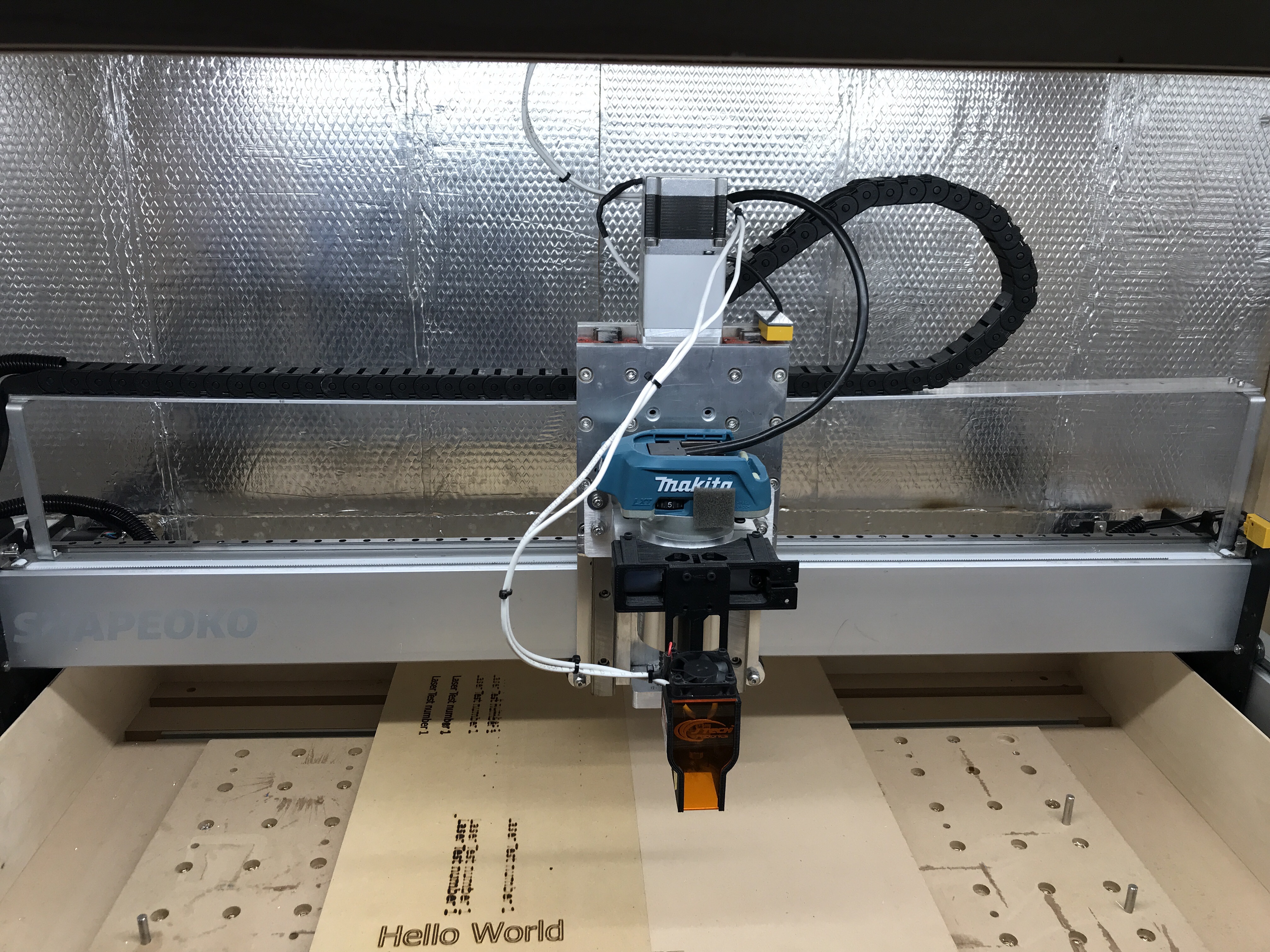
And now, to the pics…
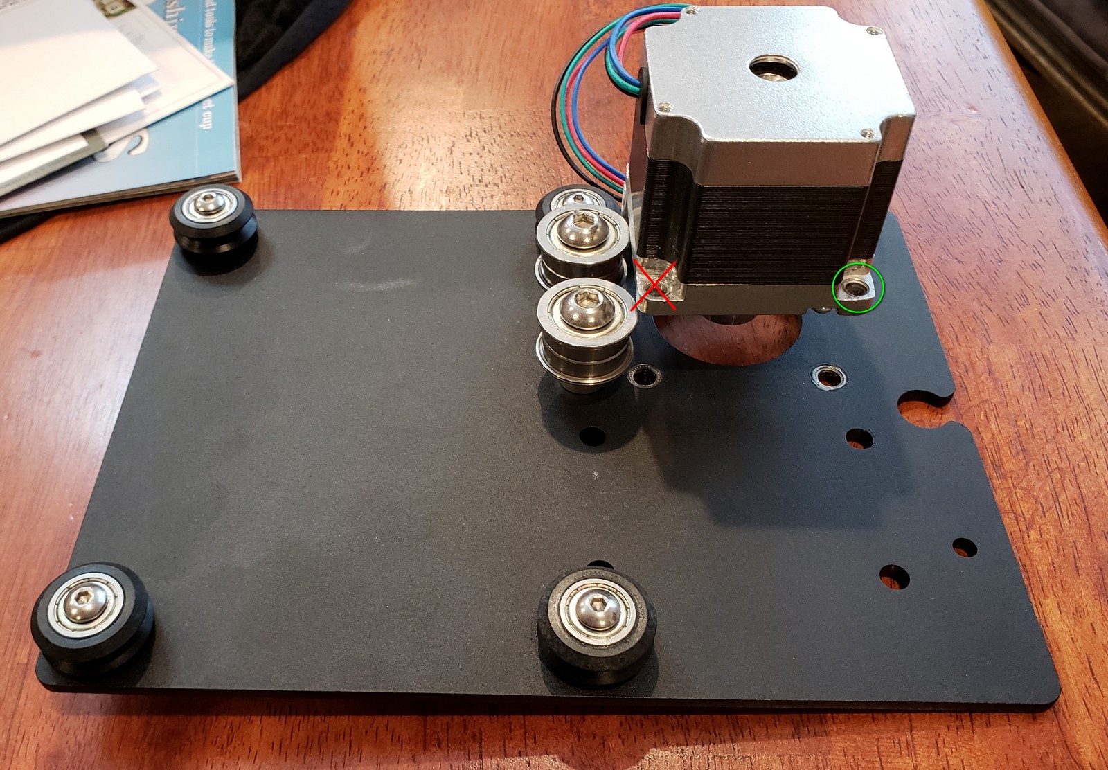
With the flip, I am unable to use all 4 of the mounting locations for the stepper. I’m sure it’ll be fine with only 3. I have the other one out only for the drill jig and template.
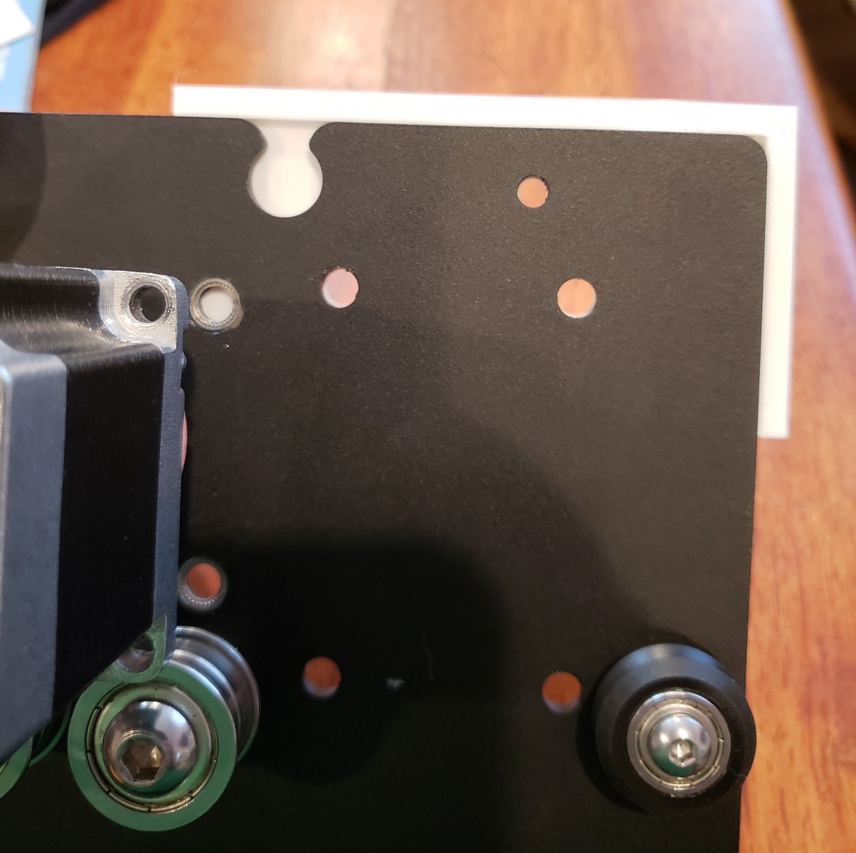
Here is the jig that has the drill bushing. The template and jig have a lip that indexes on the top of the plate and the left side of the plate as we are looking at it.
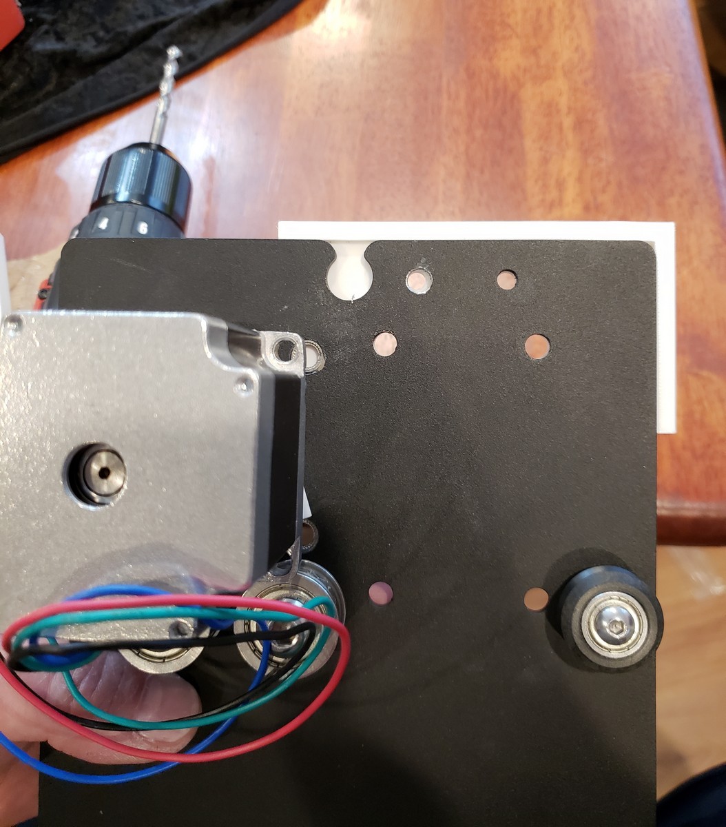
Here is the second hole. I did a better job of holding the jig in place. I used a Vise Grip clamp, but the PLA is very slippery, and I guess on the first one the drill bit caught one side first and rotated the jig just a bit.
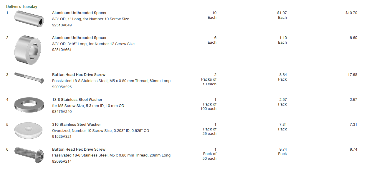
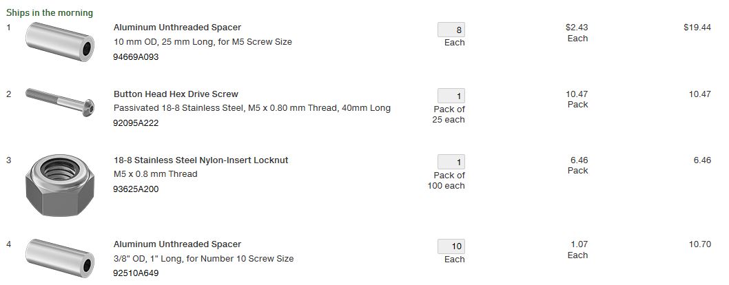
Here is the McMaster parts list for the fasteners and spacers. You can use the metric spacers, but they cost 2.5x as much as the SAE spacers, and they do the same job.
I should also mention (since you probably noticed it in the first picture) I removed the PEM nuts, because they are now on the wrong side of the plate. I’m not sure if they are re-usable, but I now have 8 of them in a bag, waiting for use or disposal.
So your plates are substantially different from mine. I have slotted holes and use screws and nuts to attach the motors. You have PEM nuts and no slots?
Yes. The Carbide team really worked on speeding up the assembly of the plates. Putting a fastener in a PEM nut is so much better than having to hold a hex nut, the part or parts and screw it all together.
Well, I haven’t actually put the machine together yet, but I think that if I were drilling the correct sized hole, I would move the hole away from the front edge of the extrusion where the V-wheel rides by 0.5mm to 1.0mm. This page here by Luke has a quick video that shows how even removing the powder coat from the inside of the hole might be enough to stop the V-wheel from hitting the belt clip.
I’m probably making my own Y plates for a second machine, and my plan was to move it a mm back. I’m exploring other methods for securing and tensioning the belt too.
I seem to be following right behind you in the Y-plate flipping department. I’m running an XL, and I’ve been doing spindle+laser projects recently. The laser is offset -87.2mm from the spindle in the Y axis, so I only get something like 180mm of prime usable Y (on the bed and reachable with both the spindle and the laser). That’s too little for some of my planned upcoming projects, making them unnecessarily inconvenient, so it seems now’s the time to get shifty in Y.
When I was doing another walkthrough of my planned procedures this morning, the only outstanding item I noted was the Y-axis limit switch. With the plates swapped, the limit switch mounting is by the forward edge of the now-right Y plate. I figure mounting it there and attaching a block to the rail to provide the necessary offset should be a cromulent solution. (The line conveniently included in the extrusion makes it pretty clear that there shouldn’t be an interference.) I’m just curious about what you did (or are planning to do).
I haven’t worked on them since my last post. I hate it when life gets in the way of the fun stuff. I was going to do something similar to what @ItsDan did - use aluminum spacers or a folded aluminum bracket to put the limit switch in the correct location. I have the Precision Limit Switch set from @Luke, so the mounting will be slightly different than the C3D limit switch set.
I’ve been away from here for months as my shop is just unbearable in winter. With spring in the air I poked my nose back here in the Carbide Community to find this little gem. I am ordering straight away for my XXL!
I had attempted to champion the Shapeoko Users Group XXL Al base buy many months ago but literally little to no takers. The moral of the story, good things come to those who wait. Thanks for posting this thread!
That’s a great idea. I didn’t think about grinding away the spacer. I am definitely going to do that. I just need to order a few more. I ended up using those two elsewhere.
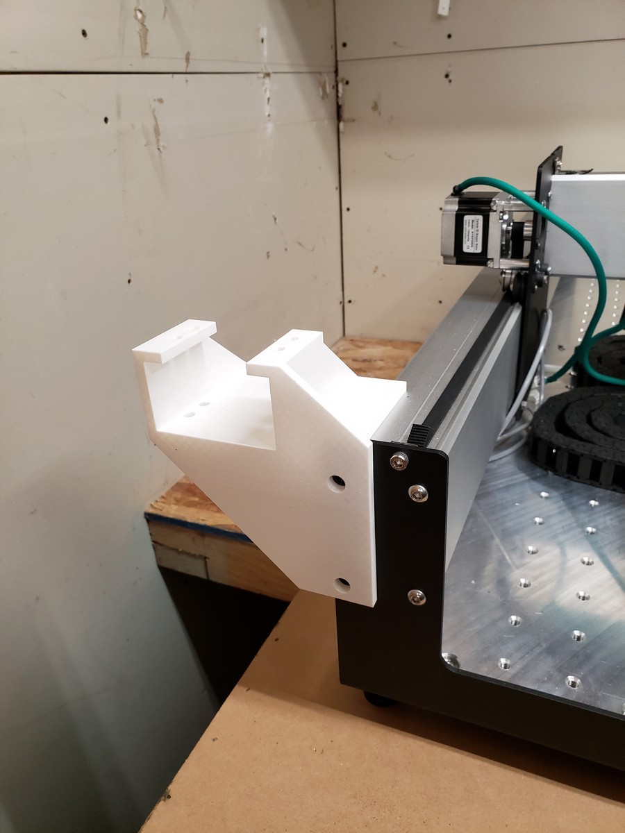
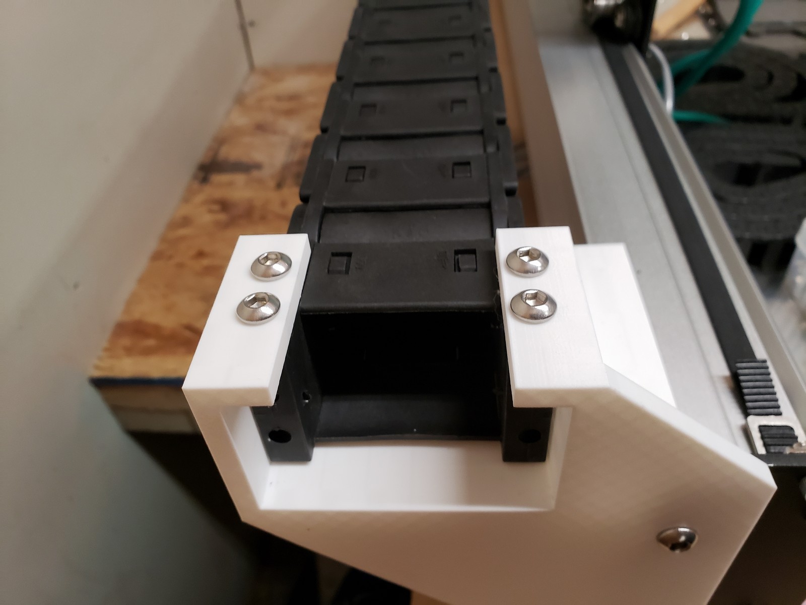
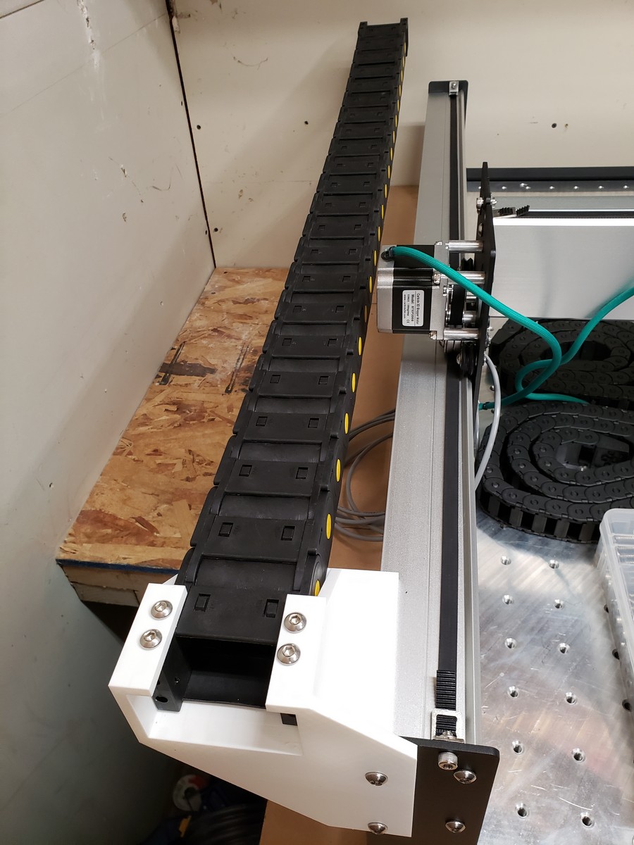
I’m glad the drill guide worked out for you. I now have all of the mechanical parts assembled (minus the spindle) and now I just need to work on the routing of the wiring. I ordered some drag chain that will hold all of the wiring, but it will not be here for 2-3 weeks. It has an internal cross section of 1.5in x 2.0in so I can run everything (VFD wire, coolant tubing to and from spindle, and all of the stepper motor and end stop wires).
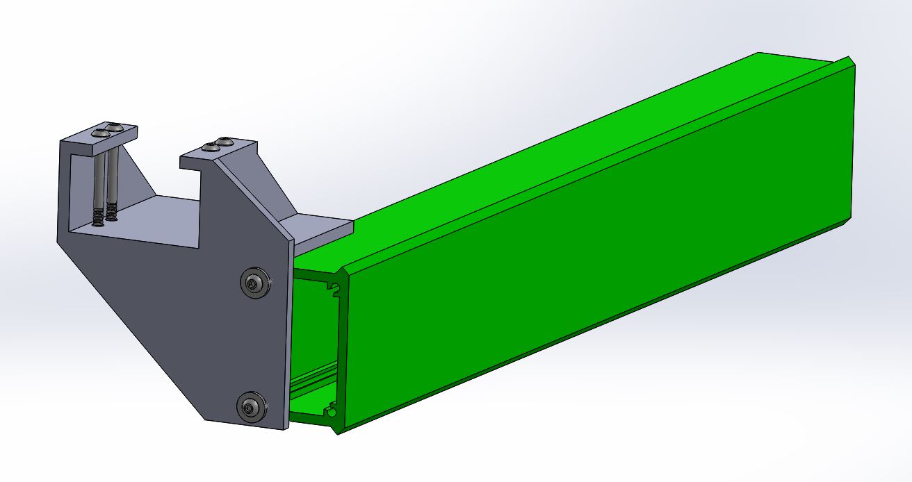
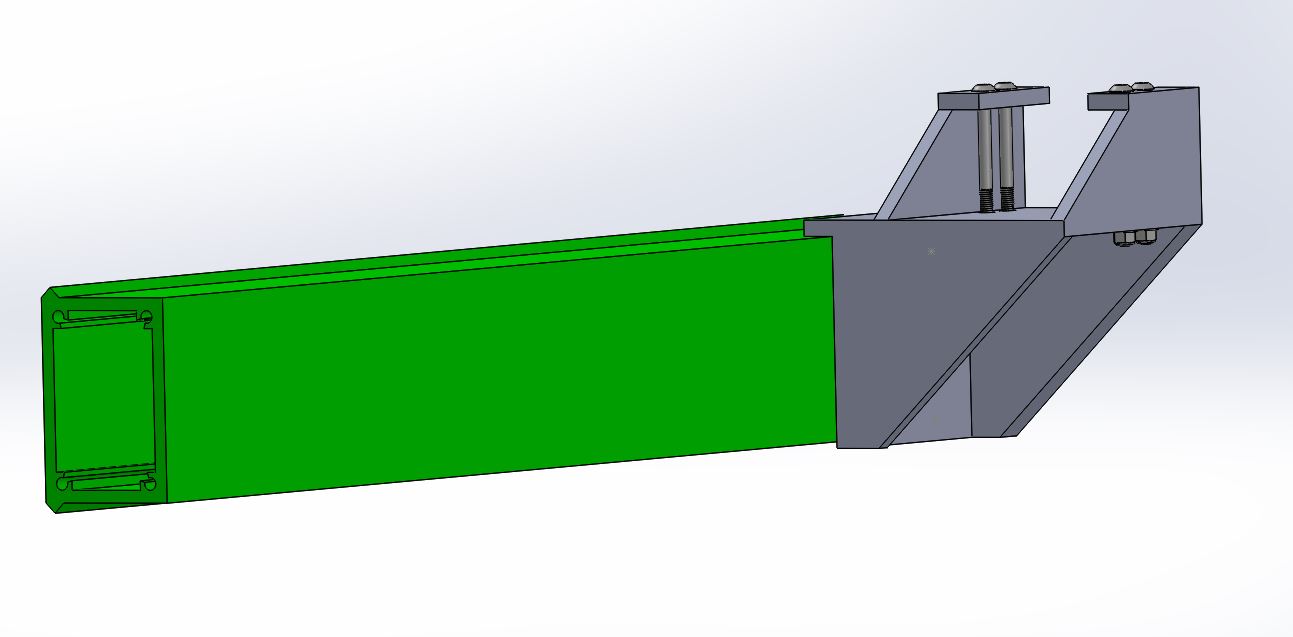
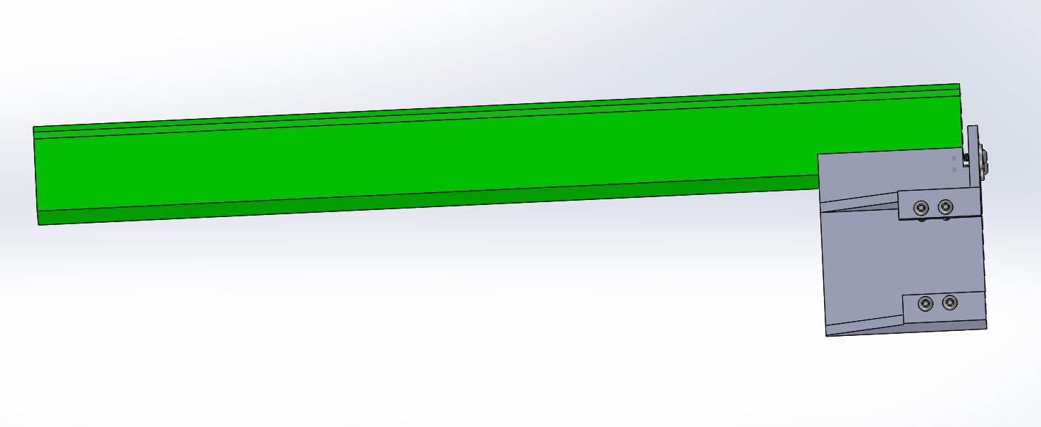
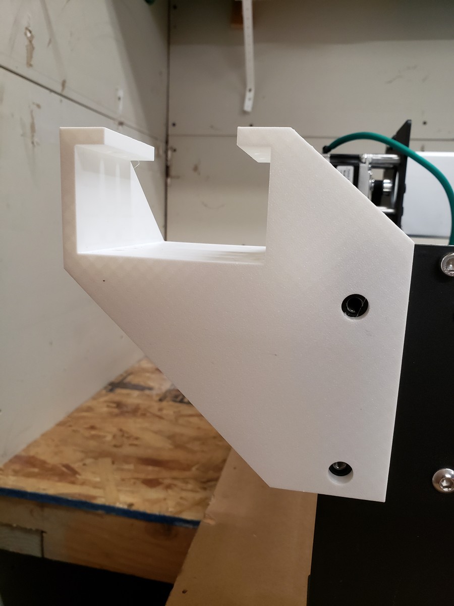
Printed it at 1 perimeter and 10% infill just to check fit.
Looks good to me. Other than adding some fillets here and there, I’d say it’s done. McMaster-Carr order already placed for the fasteners. The large opening around the fasteners are for 3/8" OD spacers. The 3D printed part is 0.20" thick and the spacers (0.253"-ish by 0.0375") by 0.1875" long are in case I crush the 3D printed part - then the spacers will take the stress to ensure the end bracket is secure. I ordered longer fasteners as well for those two fastener holes.
I’ll paste the files once all three brackets are finished in case anyone else wants to order the ridiculously large drag chains - which to be honest - are growing on me.
Prusa i3 Mk3 upgraded to Mk3s. Actually, it’s the first print after upgrading the hot end to the Mk3s hotend parts.
I cannot recommend this printer enough. With a Raspberry Pi 3B and Octoprint, it is the best setup ever. Yes, I am biased, but after having a cheap $200 acrylic Chinese printer, this is the easiest and most low maintenance printer ever.
EDIT: Full disclosure: I owned a MK2 and Mk2s and two Mk3’s and the MMU 1.0 and the MU 2.0. I sold the two Mk2’s.
Griff
(Well crap, my hypometric precursor device is blown…)
20
@MadHatter, like your design, looking forward to your sharing (hopefully) the Fusion file. I’ll need to make mine a bit deeper in Y to clear my linear support hardware.
I’ve had a fat DC sitting in my spares drawer along with a JTech laser for the past year. Just today got the laser reconnected. The new magnetic mount seems like a great idea. Just need to add some connectors for the laser/fan at the juncture with the DC to make it useful.
I went high with my temporary DC mount. Funky but practical.

 I was going to do something similar to what
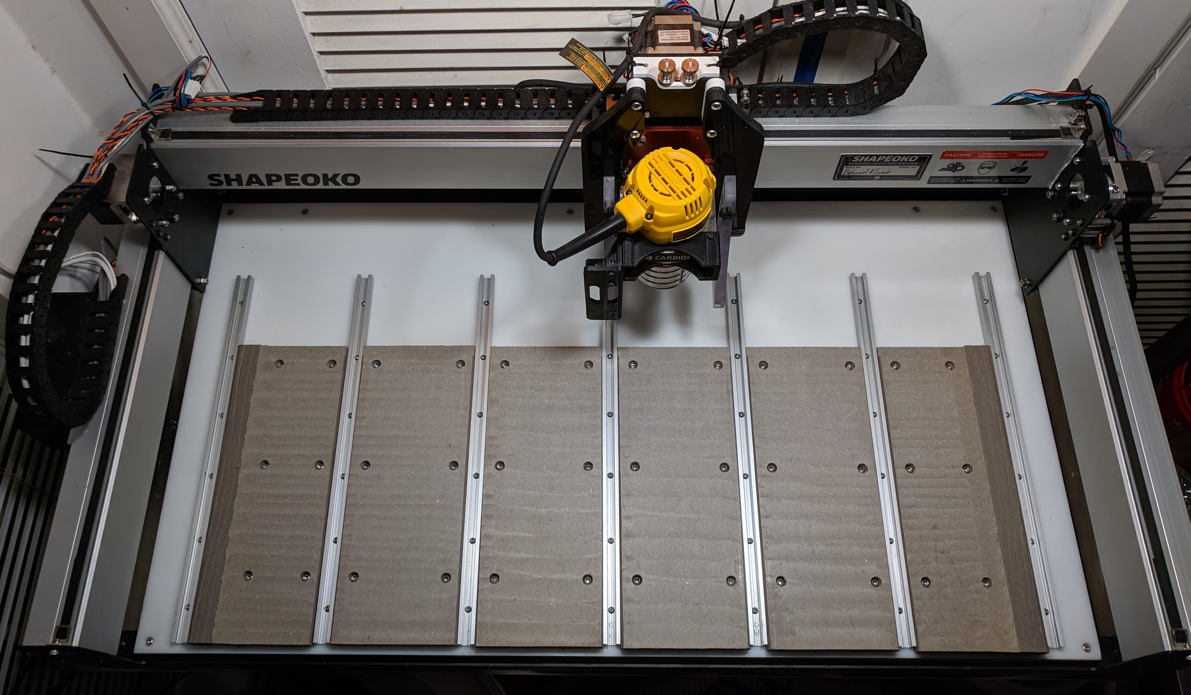
 Ohio Diesel Parts LLC
 Shapeoko XXL Fixture Table Custom Metal Aluminum Plates 600+ Mounting Points