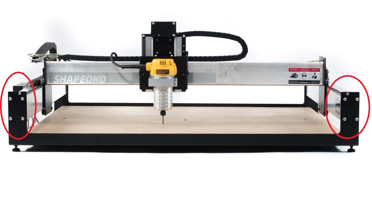
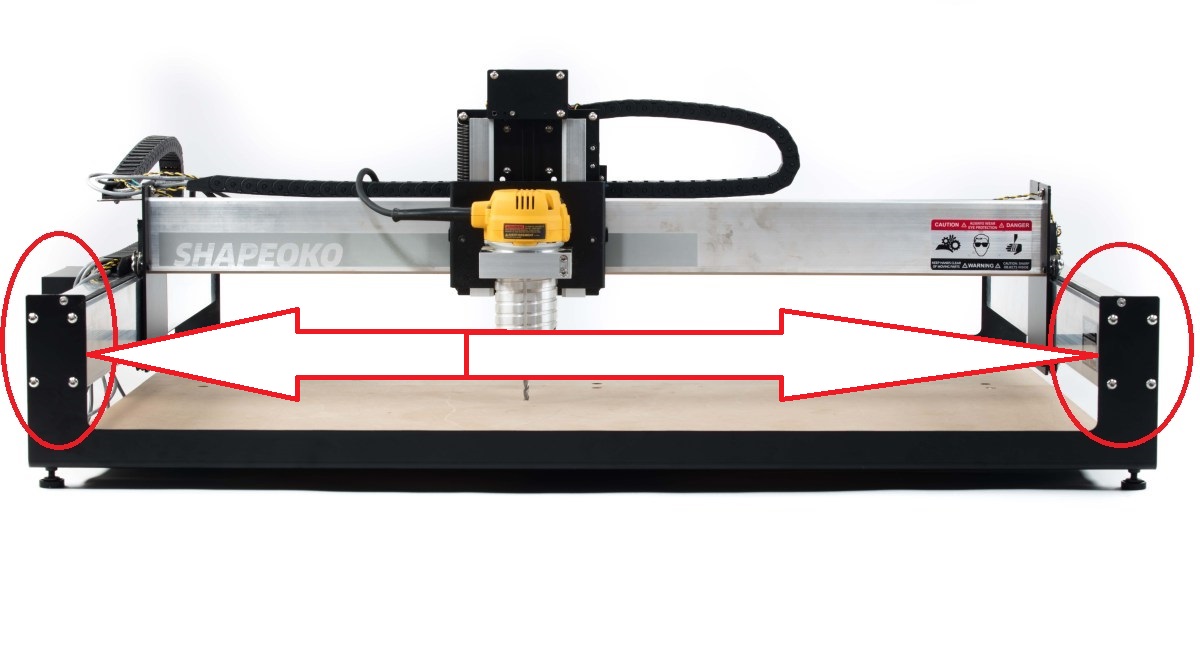
Soo I have spoken with several XXL owners and we all share the same frustration with how poorly the base frame assembly is put together for the XXL. We can see how it would work for smaller models but the larger size definitely has issues with the entire frame bending without applying too much pressure. But I have a plan and I am looking for just a little help if anyone has this.
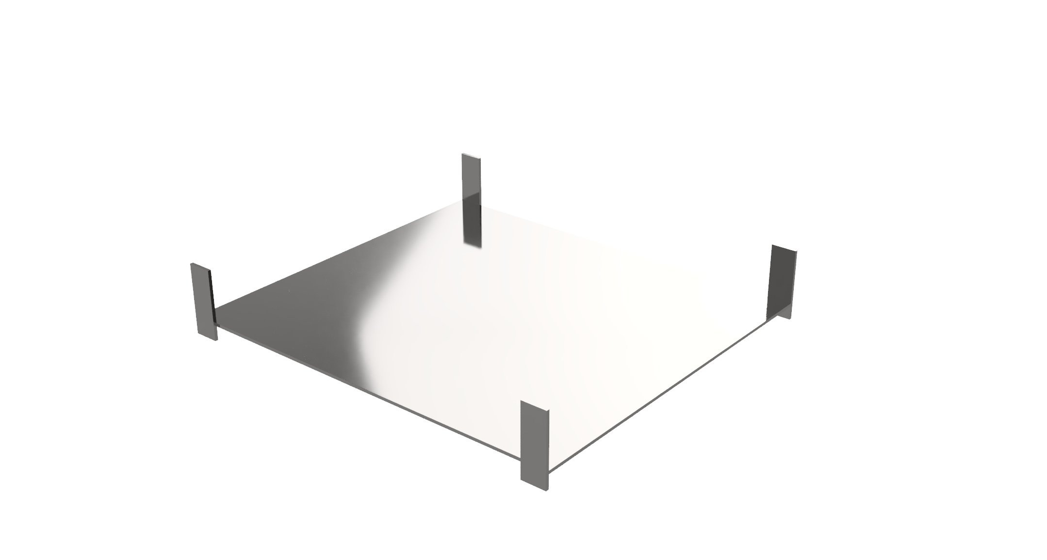
I am working with a guy at a local iron shop to get this very simple but very effective base frame assembly made. The piece is made from 3/8" plate steel and the 90° pieces the Y-axis rails will be attached to will be welded. Then the bottom will have angle irons welded onto it across preventing ANY bending or sway in this new base frame assembly.
I don’t want to disturb my machine to get the answer but I was wondering if anyone knows the exact location for the screw holes to attach the Y-axis extrusion rails?
If not I will more than likely place the old frame assembly on top of this and drill through to match the holes myself.
I have also been wondering about doing something similar.
So, I was wondering about pricing of .25 inch sheet of either aluminum or steel, sheet and plate materials:
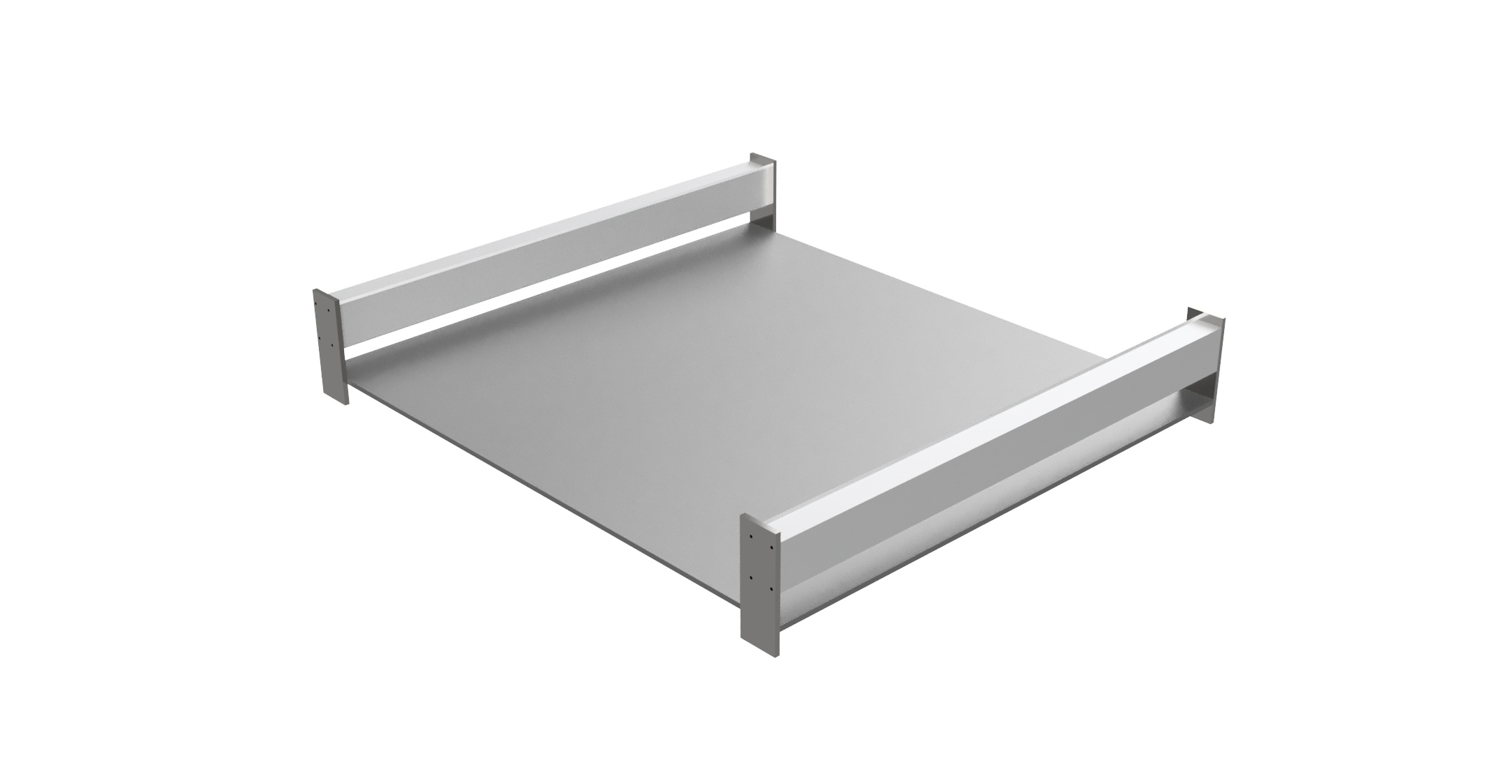
An alternative to replacing the whole thing with one solid plate would be to use off-the-shelf extrusions and welding up a box frame base. It’ll likely be cheaper (less steel in a square tube, stock shapes… ) and more than sturdy enough for the job.
With some cross bracing you could build your way up to your work-holding layer with some room for adjustments to level everything.
According to the guys I been working with to get my products powder coated the aluminum has more sway than the plate steel they used for their own workbench tables in their shop. It was the owner of the shop that even recommended welding a few t-bars underneath to prevent any kind of sway at the least bit. That being said I am going to set up his home theater and have my cost for that be taken out of the job he does for my design I sent in. I am hoping this will happen because I want a base frame that’s so sturdy I could have the table sideways and it would still be precise
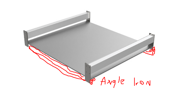
sorry about the freehand artwork…wouldn’t you want at least angle iron across the front and back? As you show now it seems to be a lot of flexing at the corners of your base. Maybe you’ve got something more rigid in mind just not shown in your illustration.
This design is using a 3/8" plate iron which will have a honeycomb-like design of welded on t-bars across the entire bottom of the waste table. So the short answer is yes, the issue of flex is the primary issue being addressed with this design and it will be hugely compensated for with the extra support on the bottom. In the words of the shop whom will be making it: “you’ll be able to drive a mac truck over this thing and it won’t give”
Cool ! I’d love to see an accurate picture of the design, it seems like the absolute solution for rigidity and flex elimination. Wonder how much all that steel will weigh ? Thanks and good luck.
I will be able to tell you in the next few weeks but this thing will definitely be heavy! The iron shop owner insisted I powder coat it with gloss black because he really wants to see me using a fine tuned, rigid but good looking machine I will definitely post when I receive it and install it.
If you’re planning to add a secondary waste board on top of the steel might I suggest that you make the upright portions of your frame an inch or so taller than stock. Reason being is I’ve got a double 3/4" waste board on top of my machine (1 1/2" total, plus any junk board I put underneath to save my “good” waste board), and with very tall items (like anything above 2 1/2" is pushing it) I run out of Z travel going up. You can always add more thickness to the waste board to use small tools in shallow cuts, but you can never take away enough waste board to cut thick pieces with large/long endmills (as I’ve recently found out by crashing my Z carriage going up, then subsequently after losing Z zero, crashing my end mill into a beautiful piece of curly maple I was trying to cut). Just a thought.
Any chance you could link us or provide some examples of the base frame bending? Or maybe some clarity to how they’re bending (is the frame bending downwards or are the front endplates bending forward, etc)
This is a bit concerning considering that I’ve got the XXL as well.