I apologize in advance if this is long winded. I took delivery of my Nomad last week with the sole intention of doing double side machine work.
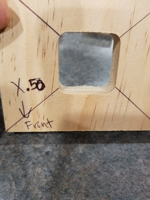
I have worked three seperate jobs, as well as a test cube I made to test this alignment issue. I have over 40 hours and numerous wasted jobs. It appears to be a very consistent mis alignment between the two sides. My thinking on day one was I needed to center the work in the flip jig with shims, and Rich very adamantly insisted I was wrong. I realize that now. I have messages in to Apollo but he is busy and I hope that an open forum discussion will help resolve the issue so the machine can be put to work.
I would gladly PayPal someone who can help solve this issue, at this point since I have not received much support other than to make sure I pull on the flip jig.
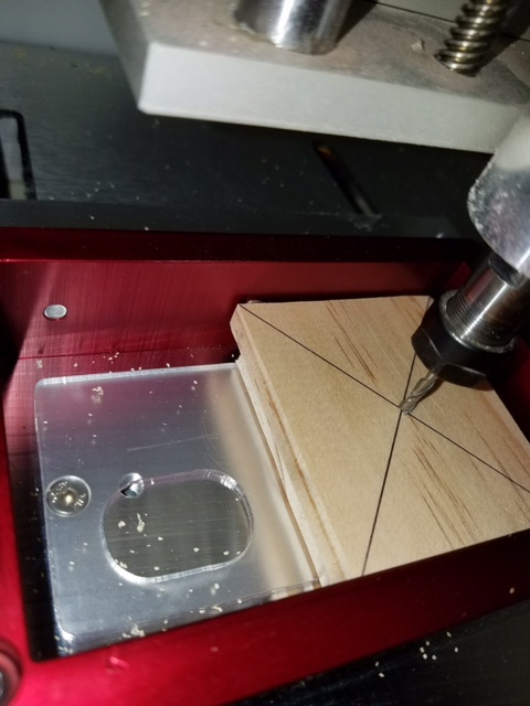
After thinking that the jig was creating an issue, I began placing my work in the bottom left (SW) corner and zeroing X Y by locating the edge, and then adding .159mm to center my .125" end mill to absolute zero SW corner. Using this method, the completed work is identical in mis alignment as if I was using the jig. At this point I would much prefer to work by locating the edges, and do away with the jig all together as it allows for more fixturing options. The one issue I see with edge finding, is if the stock is not squared up really well. If reference point at SW corner is taken and set 0,0 side A, and the work is flipped to side B and 0,0 is set and those two corners are not squared up it will create issues. Can anyone attest to this?
When using the flip jig, I rapid move to center, and then move X to the center of my work, being sure as to not move Y.
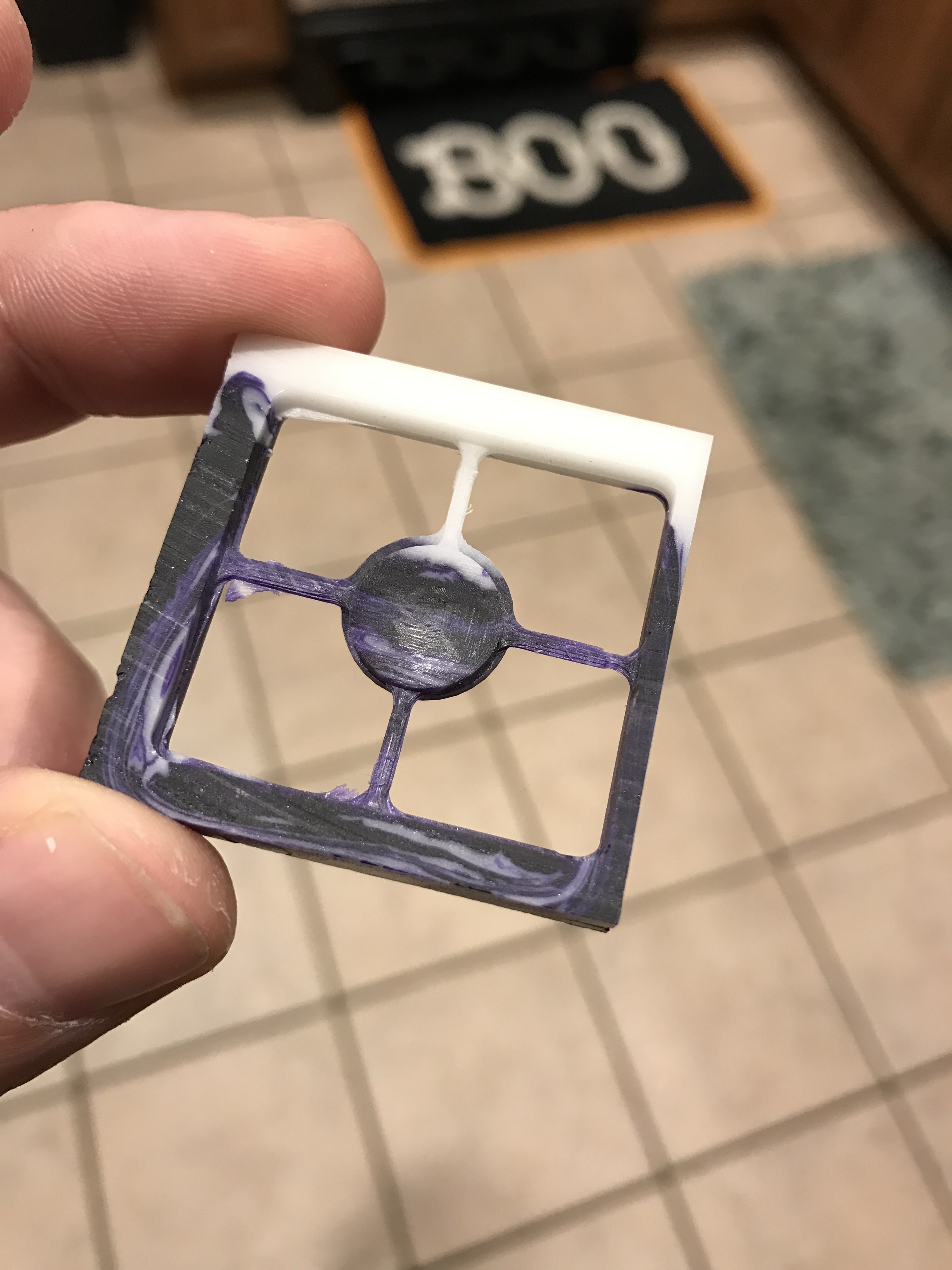
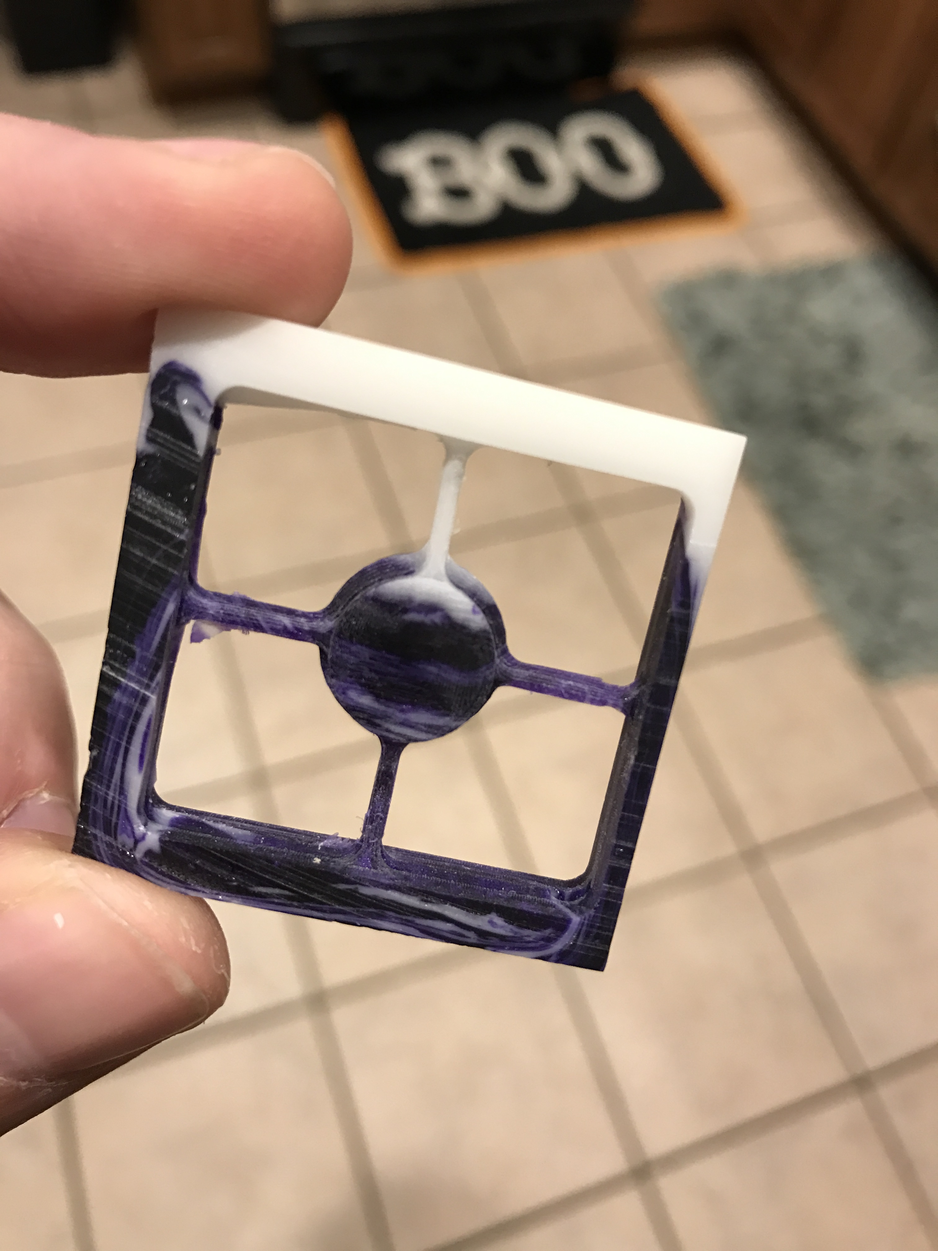
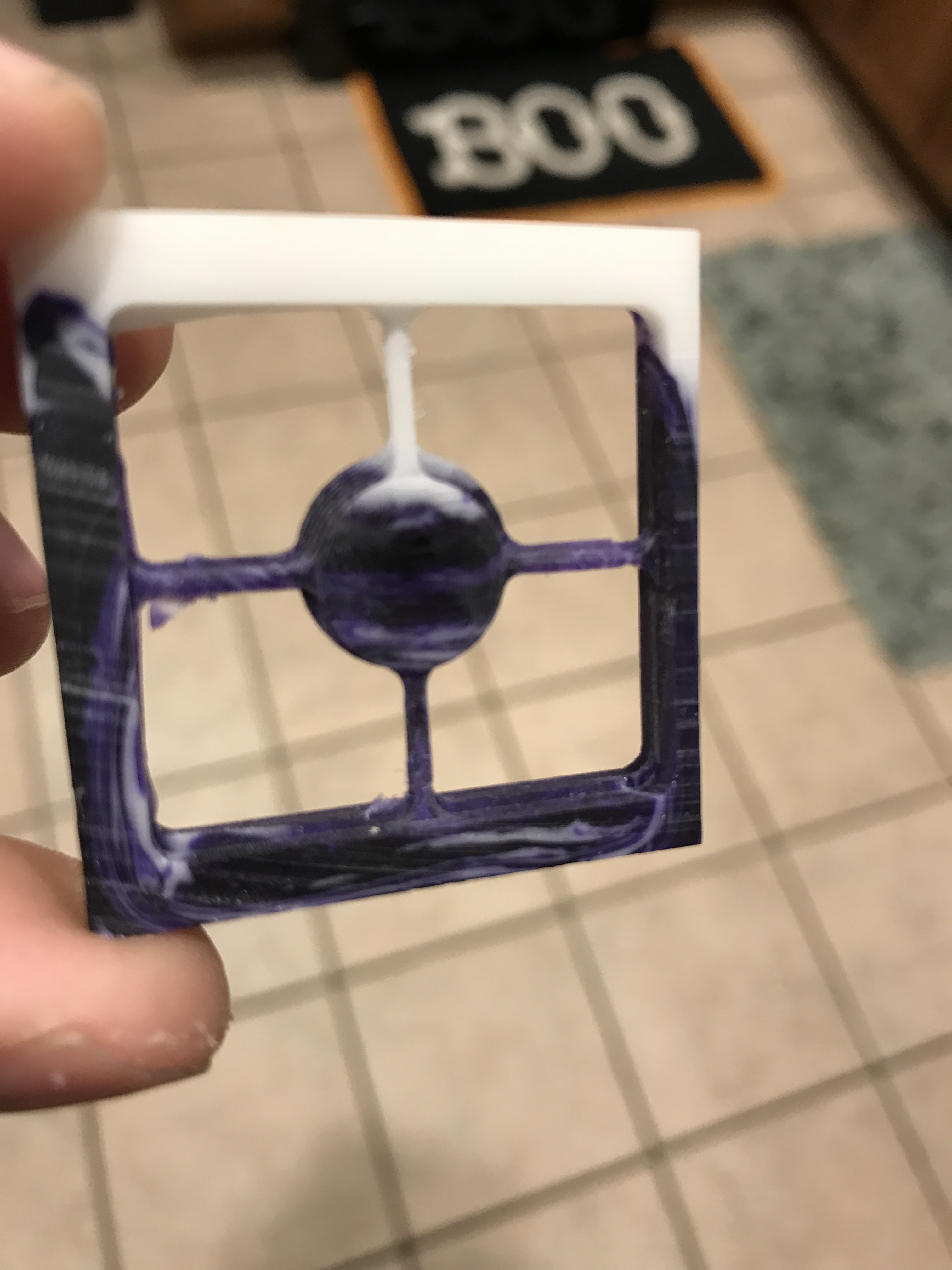
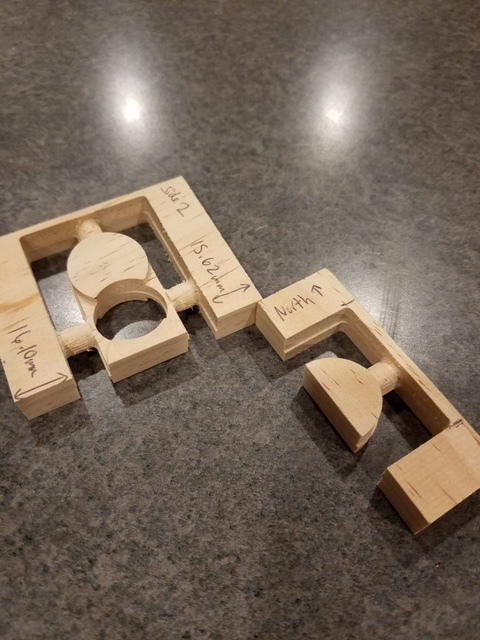
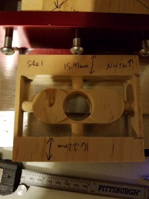
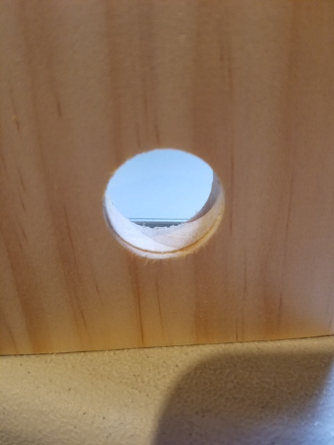
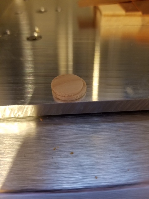
I will attach one of my most recent failed files. The support structures added are far from ideal for this very small part, however I added them to eliminate any issues with part movement. Typically I have moved the part to just below the surface of my rendered material in meshcam, created a file for side A, flipped the model and moved to bottom for side B. For all intensive purposes, I believe this file should work for troubleshooting purposes. Attached are only several pics of many failed jobs.
I do have a solid grasp on basic principals. I was a technician prior to real estate developer, and have worked on manual machines and lathes for many years. I have waited days before asking for help with this issue, but I have exhausted all possible ideas.
FILES:
bb button w supports.mcf (38.5 KB)
PICTURES:


Again, anyone who can directly assist me in this I am more than willing to offer some money for your time, or possibly a flip jig which does not work for me.