Yet another vertical workholding design

I’ve seen quite a few designs for vertical workholding on this forum. So I came with a few requirements.

  1. Must be quick to set up
  2. Must store without a lot of space
  3. Ideally no or minimal reconfiguration switching between horizontal and vertical milling (the use case of a box or drawer comes to mind.
  4. Ideally easy to make

A friend really is a big fan of 8020 aluminum extrusions encouraged me to look into it. (Versatile stuff. I interviewed a high school student for a college application who built a CNC routing machine out of 8020 and a Dremel.) So this design uses it for the base structure.

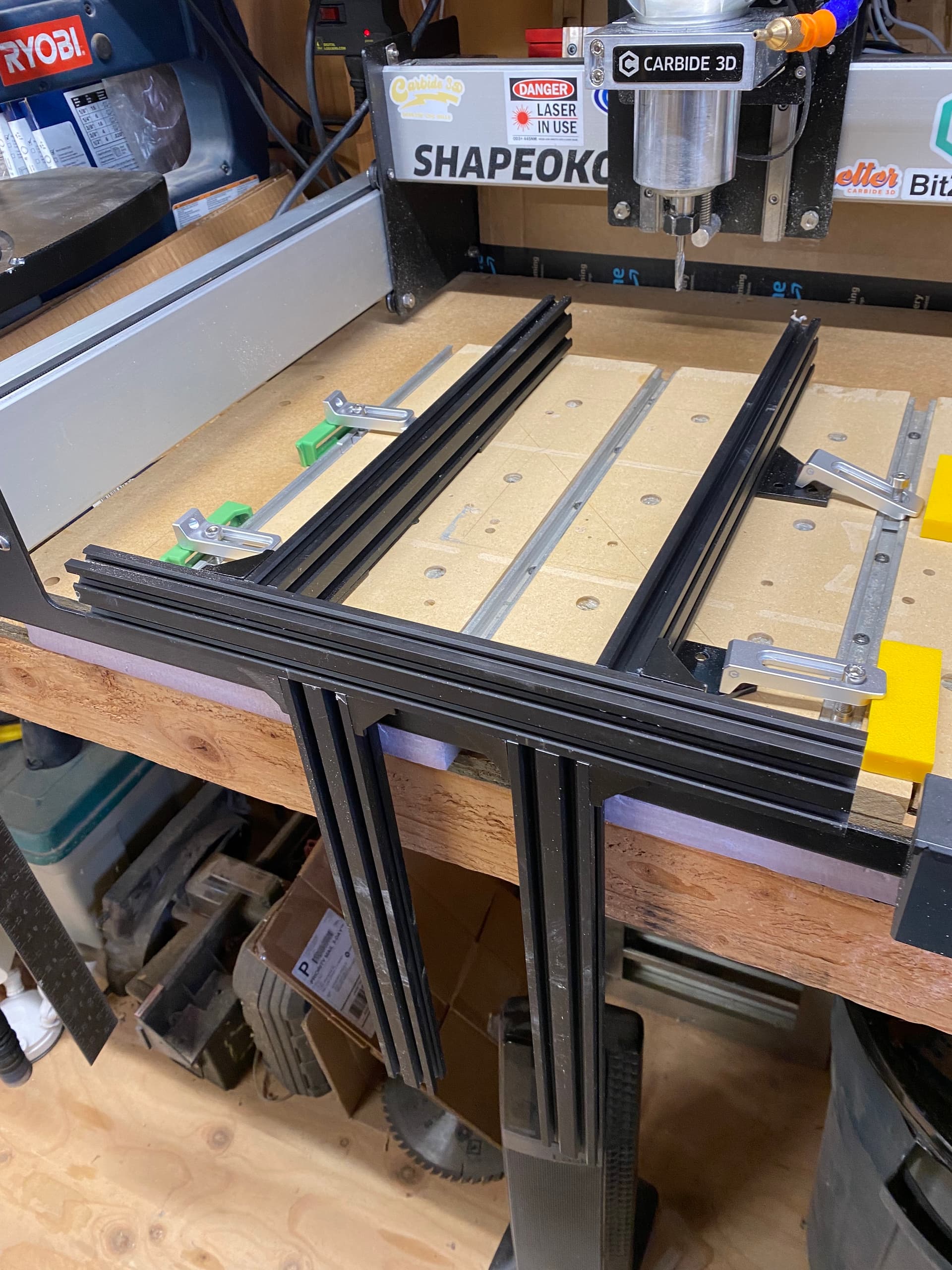
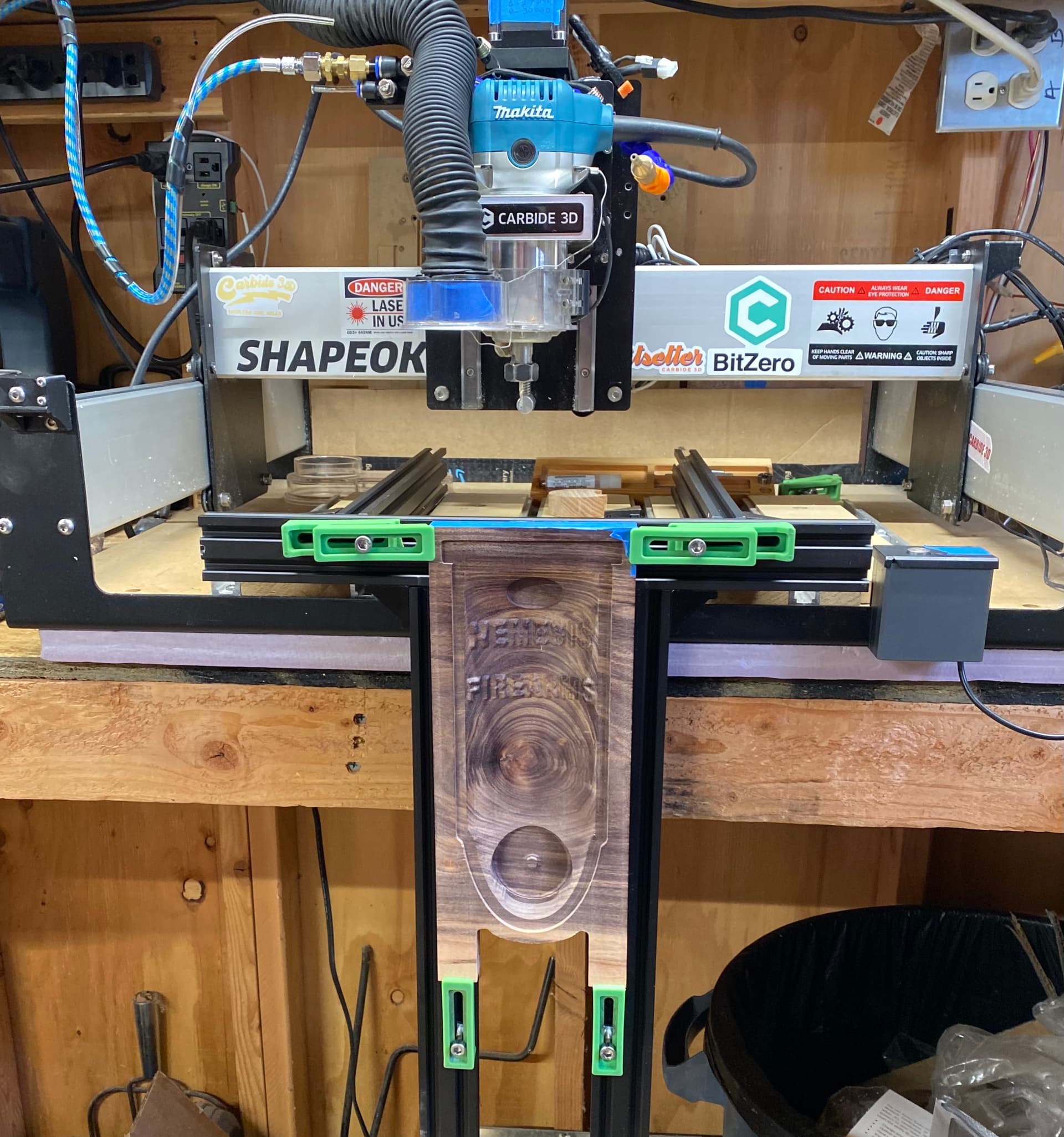
Here’s the design a picture is worth a thousand words.


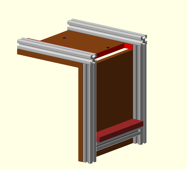
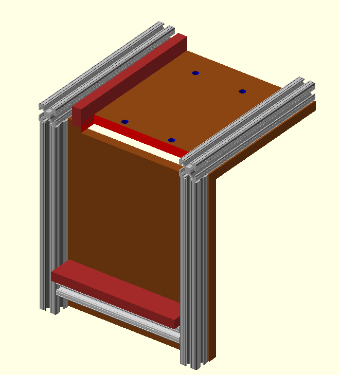
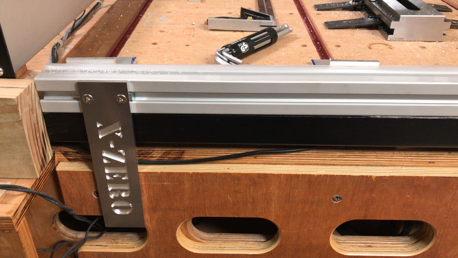
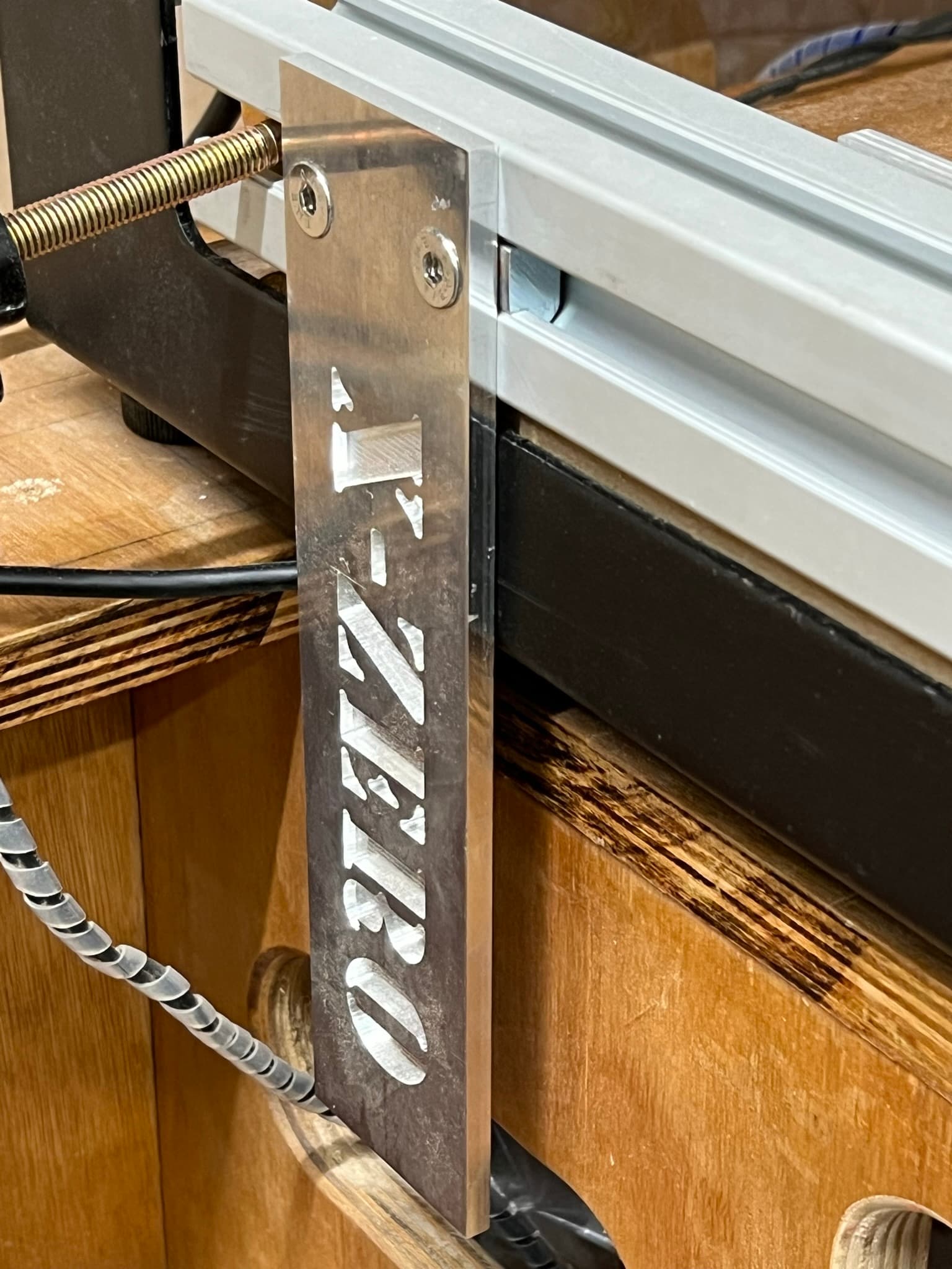
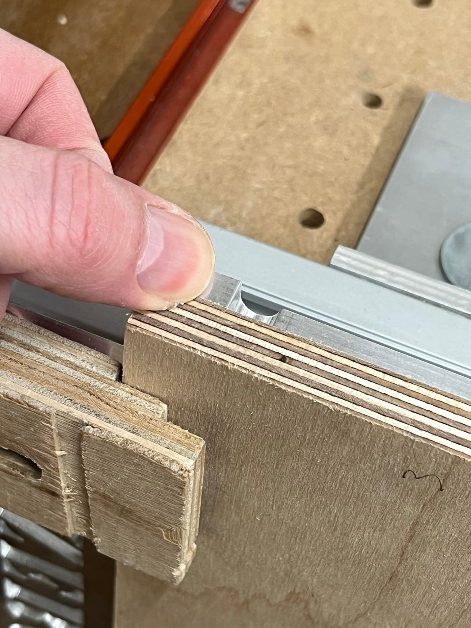
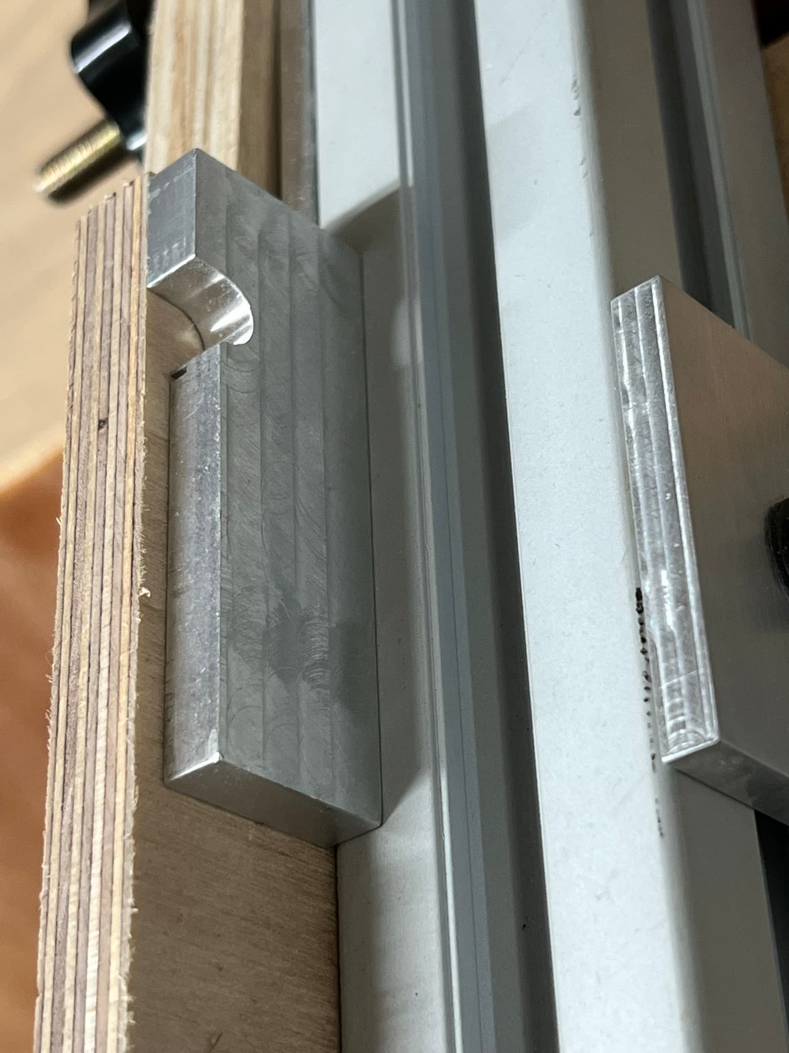
The basic idea is that two MDF boards are attached to two 8020 each (in this design 1 1/2 inch extrusions). The top board is attached through screws to the t-rails. (There is a screw hole in the top extrusions which also go through the MDF and into the t-slot where it is secured there.)

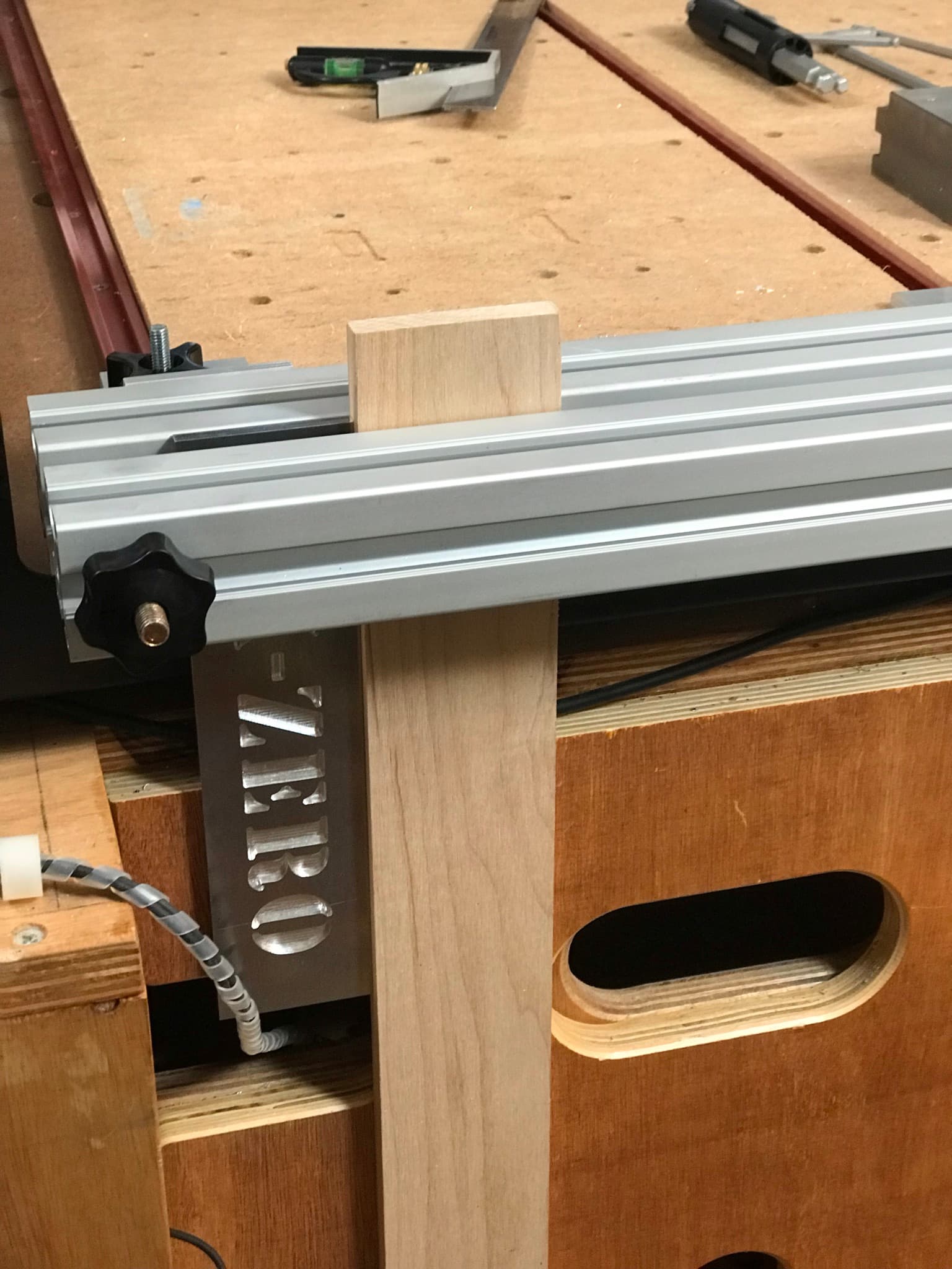
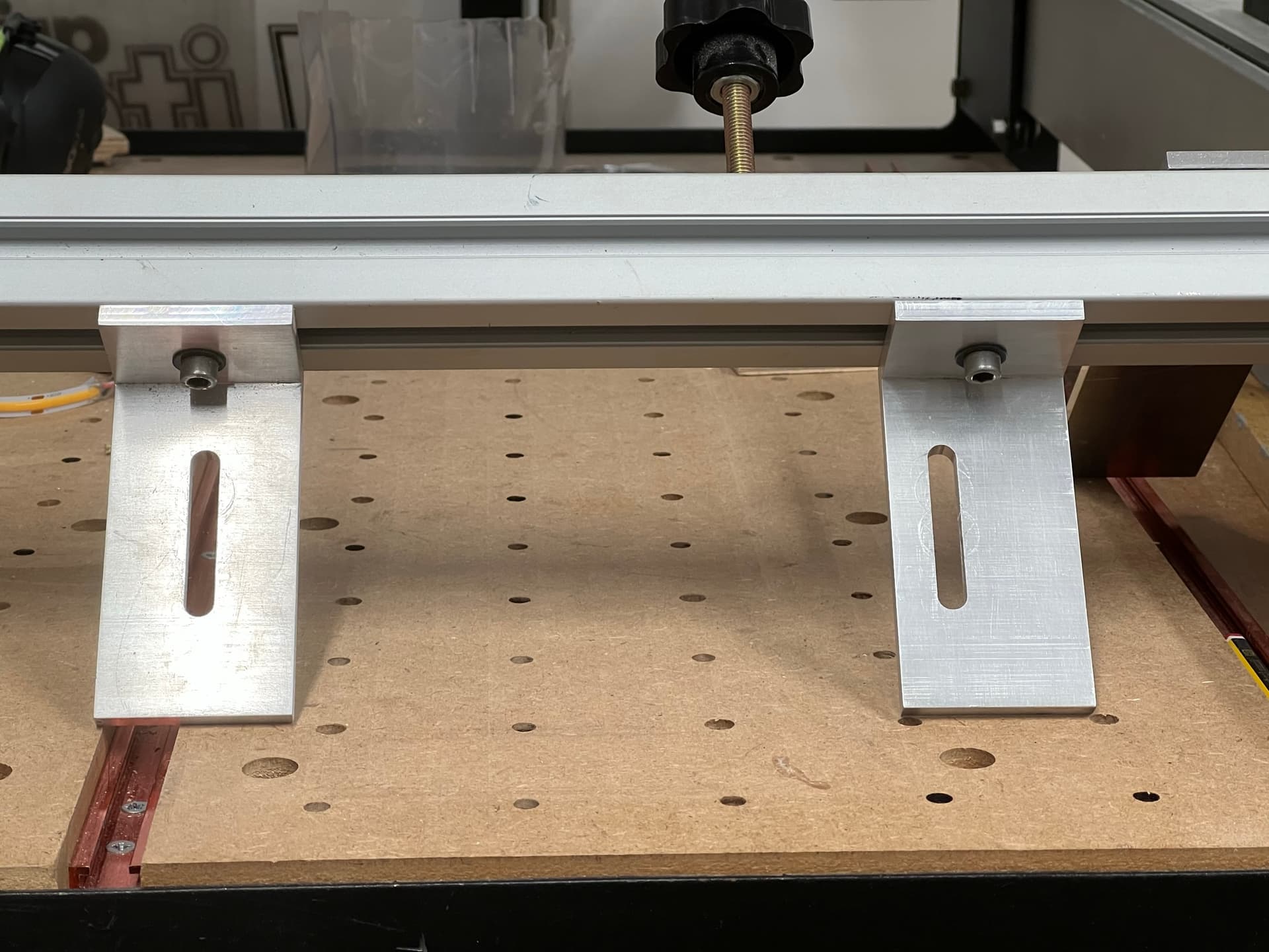
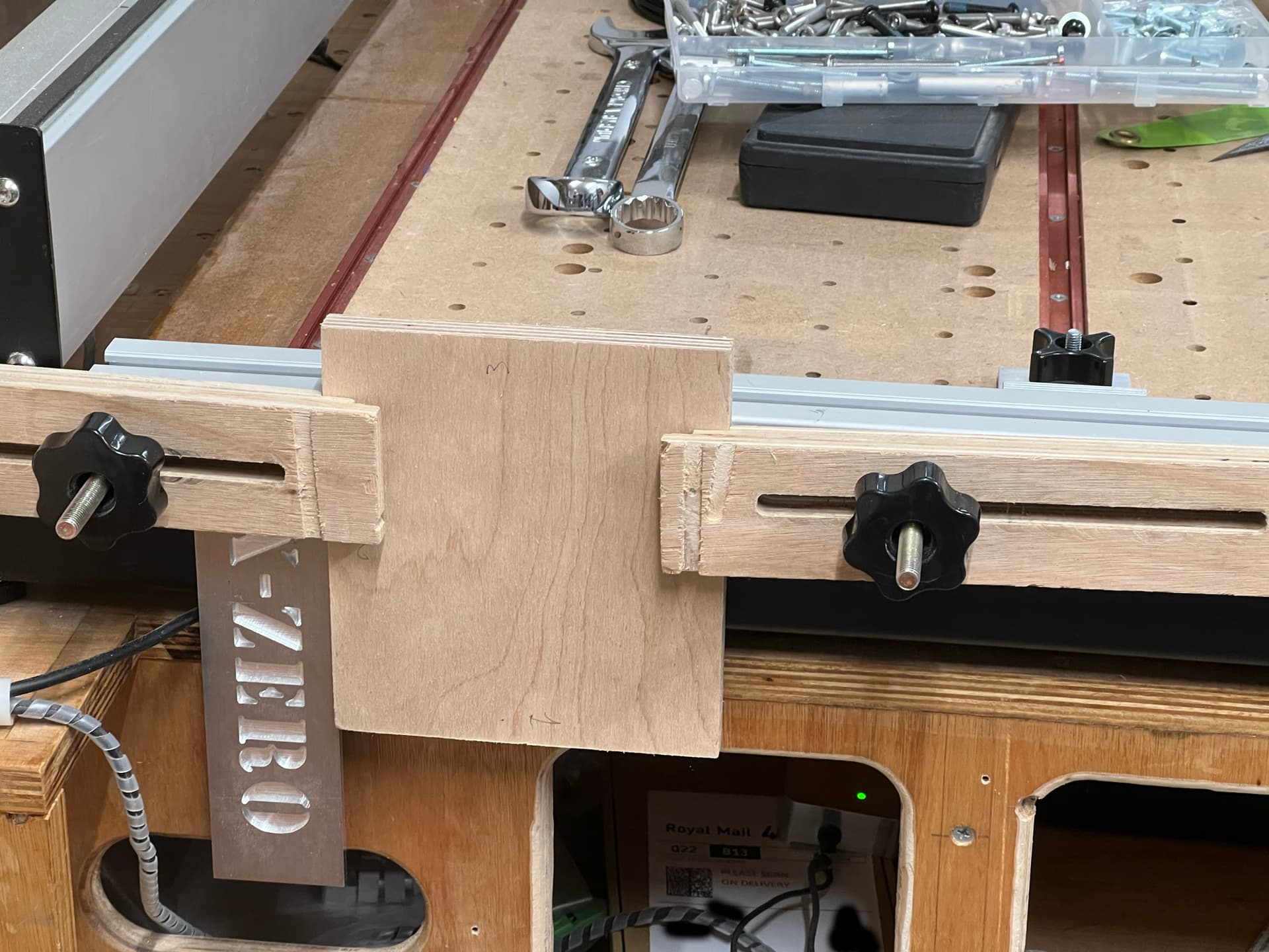
I added an alignment fence to the upper MDF so that you can easily square the stock for horizontal milling. There is also a cutout so that you can mill the end without elevating the stock or hanging over the end of the CNC. The bottom has an adjustable arm with a fence that can maintain the height of the vertical stock.

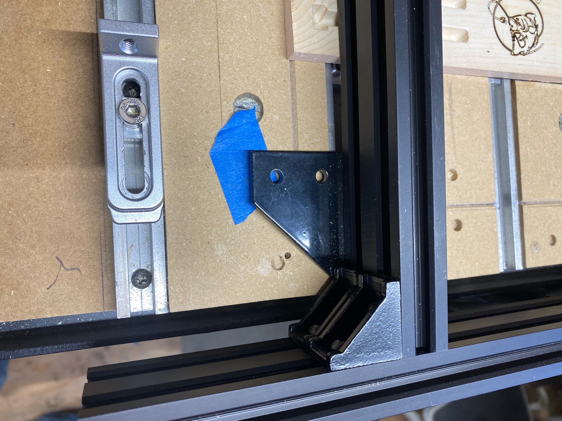
The two halves are fastened by fasteners in the 8020. I figure the jig could be disassembled for easy storage.

As for workholding, I haven’t figured it out. The two MDF boards could have threaded inserts installed. Which would give the greatest flexibility is also more work. I’m also toying with using an extrusion to go across the top with threaded openings to form a clamp.

Anyhow, this is a work in progress and would appreciate some suggestions on improving this design especially if you’ve had experience with 8020. (My experience is limited to having gotten their free sample in the mail). My biggest concern is whether fastened together the corner can hold the 90degrees under the stress and vibration of milling.

1 Like

I tried this sort of thing, and I found the ability to micro-adjust up/down and side-to-side helped a lot — that said, I found it fussy and a lot of work — any box requires at a minimum 3 setups:

  • one to cut the parts to size and machine interior features
  • one to cut corner joints in 4 side boards
  • one to cut opposite corner joints in the 4 boards

Working up joinery which can be cut flat on the machine is a lot faster, and allows a project to be done in one setup.

My vertical holding fixture, made with 4020 extrusions. This worked amazingly well once set up and is adjustable.

4 Likes

Nice design my issue is I have an SO4 so I wouldn’t clear the front. Looks like you maybe have a newer shapeoko with bigger overhang. I don’t think I can afford giving up an inch. But you have given me some ideas. Using the extrusions as a slot for workholding on the lower portion. Also using a cross beam extrusion is also a good idea.

How does that 90 degree corner between the upper and lower hold up? I don’t see any corner braces in the y-z plane.

There’s a total 8 corner braces on the fixture, it seems to be quite rigid. I’ve only used it on two projects so far so time will tell on how it holds up.

@WillAdams. I borrowed a lot from your design and am still trying to wrap my head around your flat corner box design… by the way thanks for that. I think in practice for me size of drawer and because I have the smaller SO4. I probably would have to do multiple setups anyway. I’m just trying expand my capabilities.

I have found a reliable (and adjustable) vertical edge to set the workpiece against is very useful. When running multiples, or flipping the part to do both ends, it’s also very useful not to have to re-zero X and Y.

9 Likes

Show more details, please!

Not sure if you meant my attempt, anyway, in case you did, here’s some stuff that’s good and bad about it and what I’ve learned so far…

I decided to assume my spoilboard was flat and well aligned with the X,Y so I could just use that as the ‘reference’ surface. I got some ‘heavy duty’ 4040 with much thicker wall thickness for solidity. I milled up a few aluminium brackets to attach it to the spoilboard at the front of the machine using the T tracks and some of the embedded T nuts. I think I prefer the approach shown in the posts above with the lengths of extrusion running along the bed.

The X-Zero is a 5mm piece of 6061 plate, a couple of Tee nuts in the 4040 to attach it and squared up againt the Z axis using a dial indicator in the collet and jogging up and down in Z. You only have to do this once. I don’t attempt to match this to any known X position on the Shapeoko, I just zero off the extrusion for Y and the X-Zero for X each time I install it.

I align the whole extrusion in Y by running across the front with a dial indicator in the collet. I guess I could use fixturing pins in the spoilboard but it’s so fast to set dial zero at one end then move to the other end and pull the extrusion to zero I haven’t bothered.

I stopped using the second piece of 4040 as a clamp (as in the previous pics above), it turned out that was a bad idea, all it did was bend both pieces of 4040 when clamped down. So instead I now use the M8 Tee bolts to hold individual clamps as below.

The lack of any front face support for the workpiece can be a pain and allow some vibration. I previously tried to align the front of the machine with the front of the torsion box but my torsion box wasn’t square enough for that. I do set the extrusion flush with the front steel plate of the Shapeoko so there’s about 70mm height of flat for the workpiece to align on.

On the upside, I can machine the full front overhang of the SO3 which is nice. The other designs above could do this too by removing the downward facing extrusions so probably still a good design element.

I place the workpiece up against the vertical edge and this gives me a repeatable X, Y = 0, 0 or repeatable enough for wood anyway.

When I have a set of parts to run with the same toolpath I use a fixed height block to set the workpiece to the same Z height so I can just repeat toolpaths.

Things I have learned from a few iterations and mistakes building front vertical clamps

  1. Your vertical cutting fixture needs to be fast and simple to set up and get level and aligned with the X axis, if it’s a PITA to do this you will likely not use it
  2. Keep the workpiece and toolpath up above the top of the metal parts of your clamp
  3. It’s very useful to sandwich your workpiece between some sacrificial scraps for cutting to avoid tear out on the edges, even sandwiched, keep toolpaths above the metal parts to avoid playing toolpath roulette, especially with paths such as adaptive clearing in Fusion
  4. If you’re a Fusion user, it’s worth modelling your vertical clamp the way you would a vice or other workholding
  5. Using two full length pieces of extrusion to ‘clamp’ a wooden workpiece only produces two points of clamping pressure and bends the extrusion if you try to tighten it up to get more clamping, a vertical face with multiple clamping points is likely a better design if you want more clamping force
  6. MDF and Plywood make for weak reference faces compared to Aluminium
  7. If you cheat with a CNC you can make really teeny through tenons with really accurate chamfers :wink:

HTH

7 Likes

I like the design. Very simple looks like it does the job. Not like my overly complicated design. Fewer expensive 8020 fastners too. The only think that might be a useful height stop.

This topic was automatically closed 30 days after the last reply. New replies are no longer allowed.