Z height problem

I guess I am having a brain fail. I’m working on a project using 1" thick Cedar and its been going fine. But now I have one toolpath that seems to be not setup correctly. When I start this tool path, the first thing it does is try to home the Z axis, but something is causing it to grind at the top as if trying to go further than the limit. I checked the Z limit switch and it seems ok when I place a metal wrench against it, but then when it starts the job, the Z height will be several millimeters highter than it should be. It only does this on this particular tool path and all others don’t seem to have a problem homing Z so I assume there is something I am not understanding about how the toolpath is setup.

I am attaching a screen shot of the screen where I setup my heights, but not sure what I am doiing wrong. (admittedly, this screen seems to confuse me)

Try checking the lights on the control board for the Z proximity switch. If working properly when the red light on the sensor is lit there should be a blue light on the terminal where the sensor wiring is plugged into the control board. Take the cover off and then place a metal object on the sensor to make the red light come on the blue light on the board indicates the circuit to the board is working if no blue light check all the connectors on the harness.

Anthony

Yes, the blue light comes on when the red light is triggered by a wrench. I really think its something I did wrong when I setup the 2d couture tool path. Since the settings for the tool path don’t seem to be saved after creation, I have no idea why the older toolpaths I created differ from the one that is not working. That’s why I sent the image of the height setting I used when creating this problem tool path.

I actually tried several of the previously created tool paths and did not see the problem. I don’t see any mechanical issue that might cause this. I recreated the toolpath several time and had the same issue. Admittedly, I am not the sharpest tool in the box for creating toolpaths, but up till now, I’ve been able to diagnose and fix issues. This one has me stumped.

Since I haven’t a clue what’s going on, I should also mention that when I jog to the top of the z range, the problem does not occur. Only when trying to run the problem tool path.

Probably should also mention that the issue happens during homing generated by the this one toolpath and not in manual homing with jog commands.

The end result if I allow the toopath to continue, it will air cut about a 1/4" above the surface.

Here is the gcode…

Backrest Medium x 2 v3.nc (49.6 KB)

Maybe share your fusion file?

“Grinding” and you said it happens at the lower part of the cut. Could it be a wiring issue? If a plug is working loose, there would be an interrupted circuit causing lost steps.

Good luck

Ok tried to send the file but it will only allow me to attach image files. How do I send an f3d file.

No the grinding happens when it tried to home (top of z axis), not the bottom. If I try to continue anyway, it cuts air about 1/4" above the surface.

Sorry if I am not being clear enough.

Also keep in mind that this only happens with this toolpath and not any of the others I’ve previously created for other parts of this projed5

I’ll be glad to send the file if I can fiture out how.

Zip and upload or post a link to the file online?

Got it!

keep in mind this is only a small part of a much larger multi file project.

backrest only_.zip (923.8 KB)

Sounds like your project file toolpath’s are trying to raise the Z-axis past its hard limit - the limit switches do not prevent this during a program run. The grinding you hear is the Z-axis motor skipping steps as it attempts to move & losing the Z-axis Zero-point in the process.

From your screenshot, the retract height appears to be set for 0.4" which is huge! And most likely the issue with the toolpath.

2 Likes

your stock point is different between both of those setups. Did you expect the stock point to be set to the top?

Joel: You nailed it. I set the clearance height and the job ran as expected. I am not sure how I should calculate clearance, but 0.4 ain’t it. Not sure how I ended up with that I typically to with the defaults when I’m not sure but somehow I ended up with 0.4 and since I usually don’t mess with that, I never considered that as the problem. Now I know.

Thank you, everyone.

1 Like

This can be quite confusing and a PITA in Fusion and with Carbide Motion which doesn’t warn you that the machine will be instructed to move beyond limits by the GCode you loaded.

When using longer cutters or thicker workpieces it’s quite easy to end up running out of Z travel and listening for the thump and stepper grind is something I do on taller jobs.

The machining heights are explained a little here

https://help.autodesk.com/view/fusion360/ENU/?guid=GUID3EB12C22-C06B-4601-ABFE-7F1ECBABB9CE

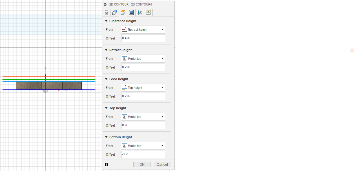
But, taking your screenshot as an example what you’ve got is everything set around Model Top, not sure if you’re zeroing on the top of the stock or down on the spoilboard, doesn’t make much odds to this issue.

Your toolpath Bottom Height is Model Top - 1" , not sure if that’s deliberate, but if your model is 1" thick, you could leave this as Model Bottom, generally only override these heights if you’ve got a good reason to. This setting can be useful to override if you want to limit how deep into a model the toolpath will cut, for example to keep a parallel or other finishing toolpath from dropping into cutouts or bores by selecting the model surface you’re finishing with the parallel and saying -0.001in

Your toolpath Top Height is the model top, that’s normal, the window between toolpath top and bottom height is the normal cutting space for Fusion, although depending on how you set up your stock you can cut down to top height in steps removing stock, see here for some more info

Your Feed Height is then set at 0.2" above the Model Top, that’s pretty normal, the feed height is where the machine should lift to for linking moves within toolpaths.

Your Retract Height is set to the same 0.2" above the Model Top, again pretty normal and sets clearance for rapid moves between cutting.

Note on Feed Height and Retract Height, if you have clamps or anything else sticking up above the model, you’ll need to either ensure that there’s no linking moves that go through the clamps (plastic or plywood clamps are good) or set these heights to above the clamp height above the workpiece.

The bit that may have caught you out is Clearance Height which is set to 0.4" above the Retract Height, thus 0.6" above the Model Top. This is the height at which the tool starts and finishes each operation, and for the rapids between toolpaths.

Given your model, you’ve got

  • 1" of model
  • plus 0.2" of feed / retract height
  • plus 0.4" of clearance height
  • giving 1.6" above model bottom that the Z will try to take the tool to at the start and end of each toolpath.

If you want to check this before a job you can zero out your tool, then try to manually jog Z up to the clearance height. If it won’t go then you don’t have room for the toolpath.

For example, assuming you have Z=0 at the model bottom then you’d zero out there with the tool, jog to Z=0 and then try to jog up to Z=1.6 inches. If you’re doing Z=0 at the top of the model then try to jog up to Z=0.6 inches.

HTH