How accurate is the simulation in Create?
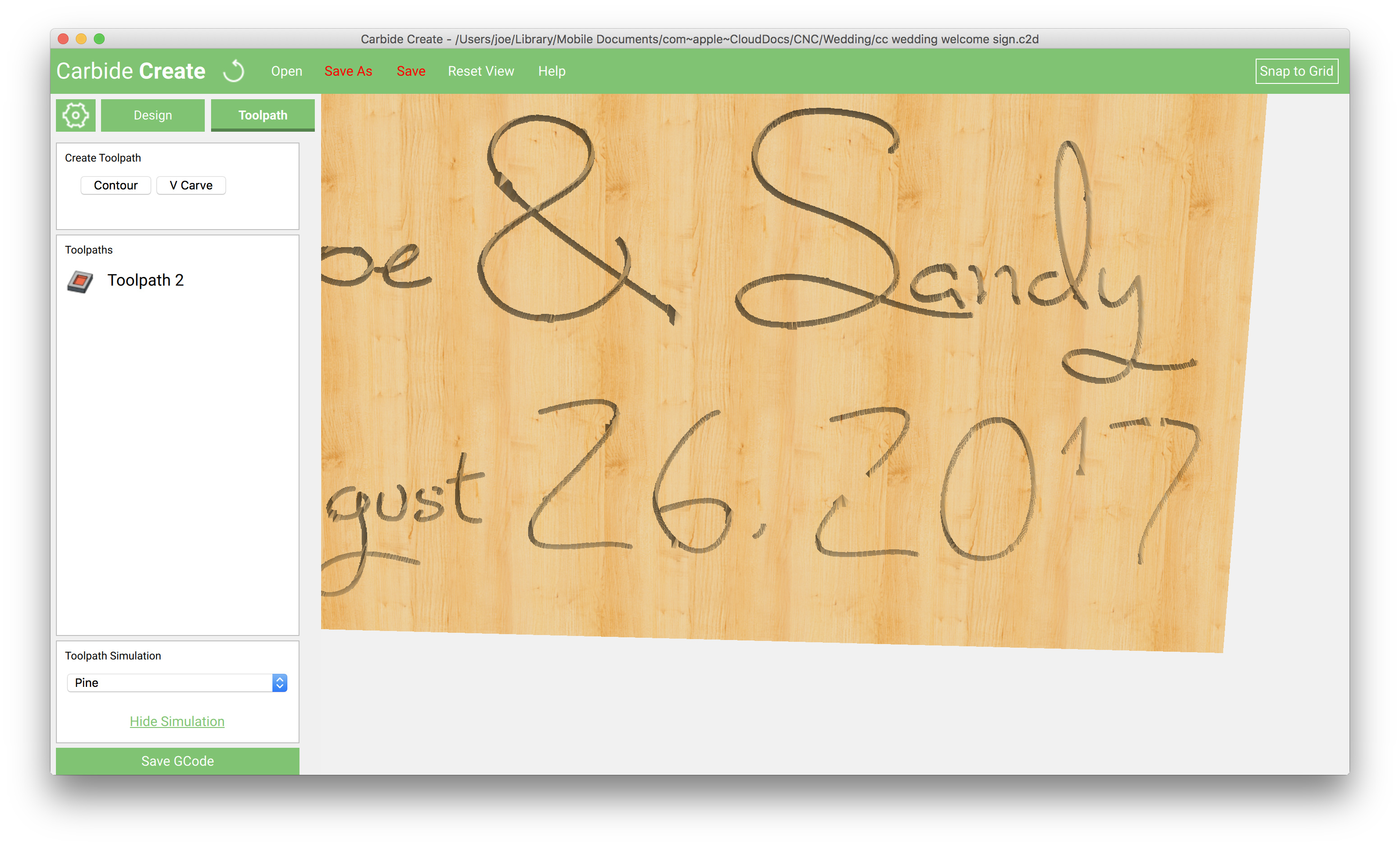
I have a simple text vector that I’m trying to pocket out. The mill is narrower than the pocket width, and the actual tool path looks good. But the simulation shows some gaps.
What am I missing?
How accurate is the simulation in Create?
I have a simple text vector that I’m trying to pocket out. The mill is narrower than the pocket width, and the actual tool path looks good. But the simulation shows some gaps.
What am I missing?
Please send in files which exhibit such problems to support@carbide3d.com and we’ll try to use them to improve that sort of thing.
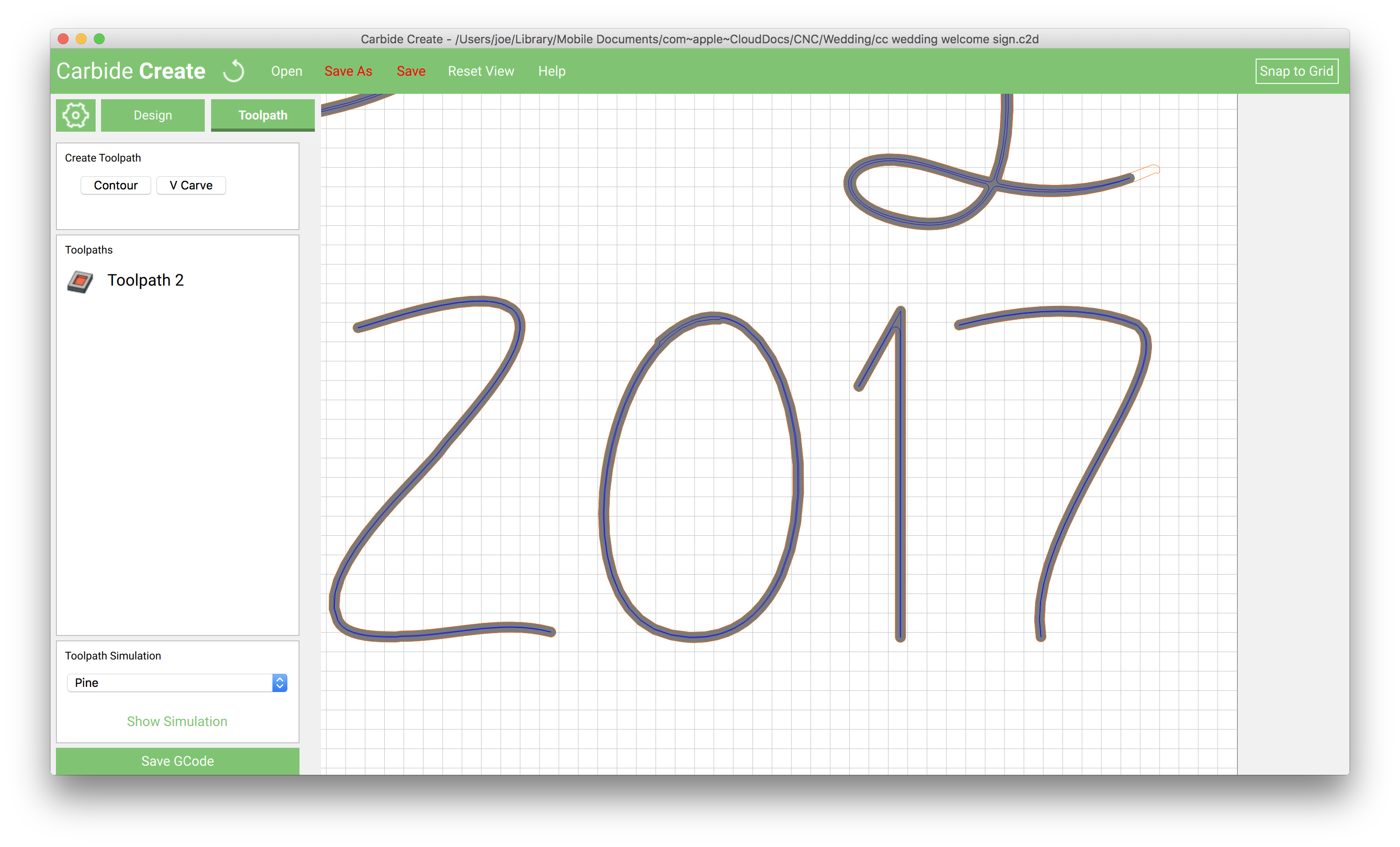
The drawn Toolpath ought to be accurate — if you encounter any instances where it isn’t, definitely send in those files.
Hey there ,
What is the diameter of tool you use to make this " simulation " ? I encounter the same problem ! When I use bigger diameter Tool the simulation is better… did you do a test with a larger diameter ?
I bought the machine to do the same thing as you and for now i encounter big problems because the parts and engraving complexity of cutting .
I did not find any information on the speed of rotation or the speed of descent and advancement for machining .
A priori to have things fine and complex it is necessary to use V form shape and then to finish the cut with another tool .
The problem in my case I can’t use Carbide creat to cut under 1mm and MeshCAM does not use Vshape cutter …
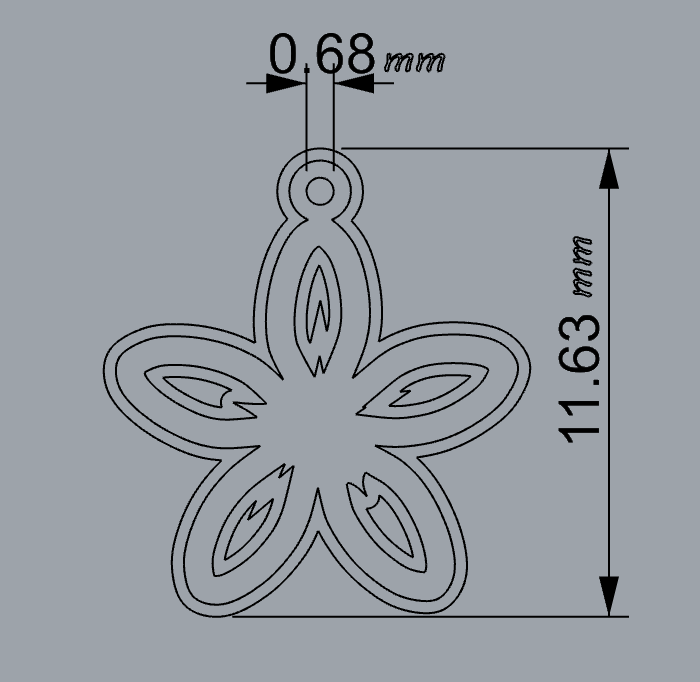
Here is an example of what i wanted to cut with nomad ( It looks relatively simple and YET …)
I’m also still waiting for a response so i can use my Nomad for now i keep doind the hand …
Why can’t you use Carbide Create to cut under 1mm? I just finished a bunch of 0.75 mm engraving?
Didn’t I draw that up? What difficulty have you been having?
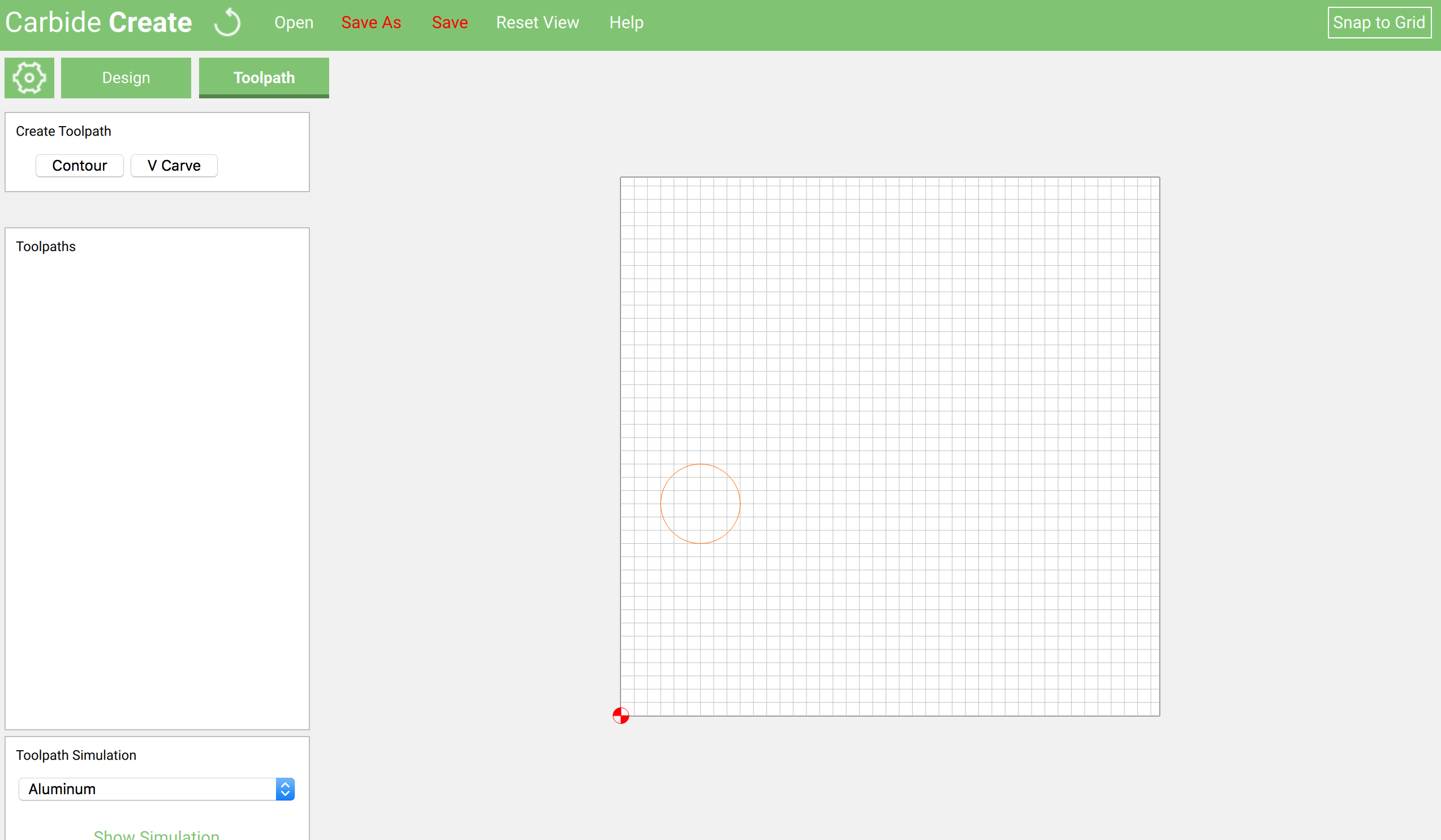
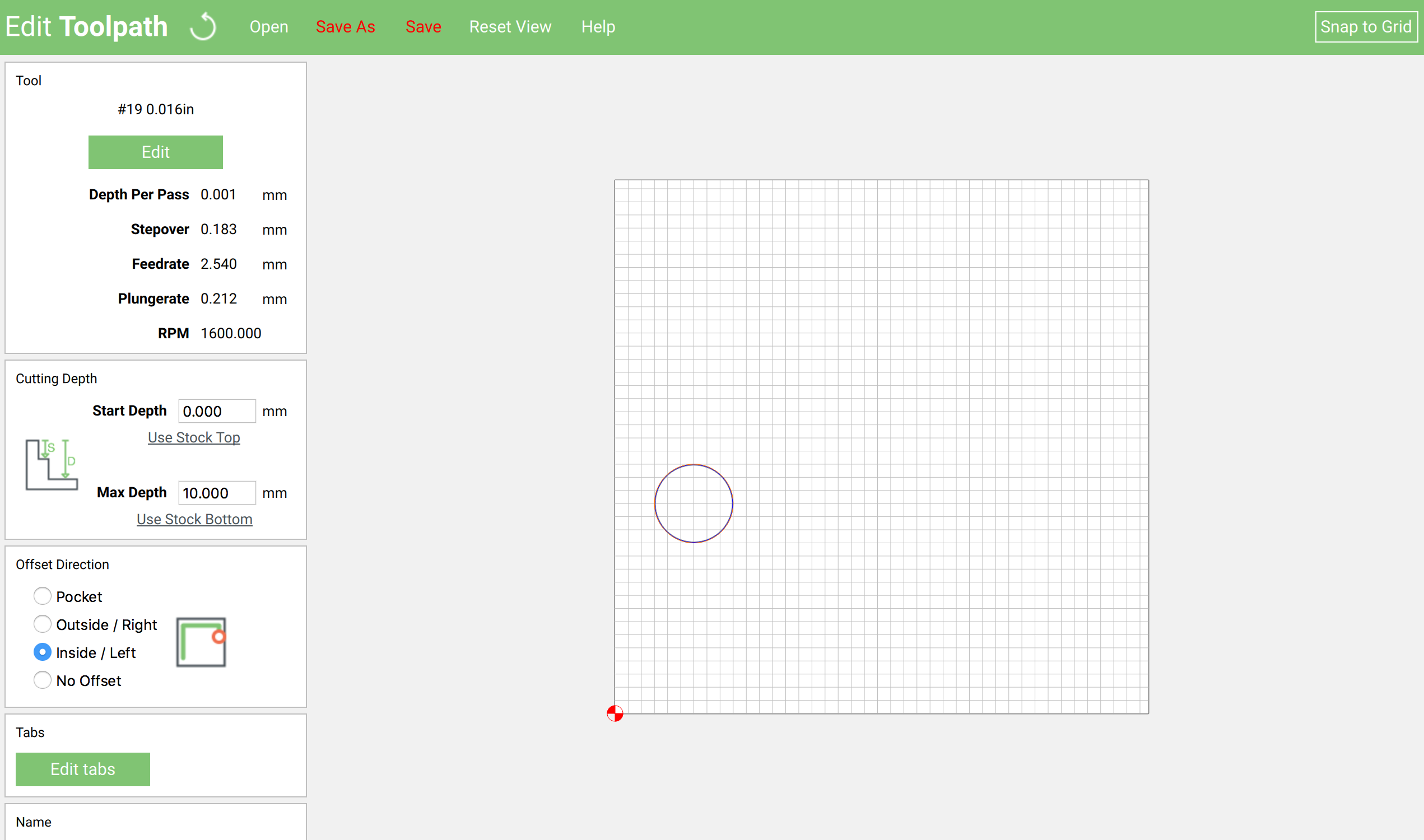
When i use the file .c2d provided by william , show simulation works … when i change my design and use show simulation it s no work … ! here a simple circle …20|517x500
Here is the result i get is what i do step by step in picture .
draw a simple circle with carbide create:
Moved this to another topic so as not to hijack the OP’s thread.
-Edward
Is that tool a .016" flat bit? Perhaps it’s just hitting the lower edge of what’s visible in a preview?
I’m with @ItsDan’s guess. Looking at the gcode generated, your job will cut correctly, despite not simulating correctly.
I’ll do a little digging into what the minimum visibility is for the previews.
-Edward
Yes it 's .016" flat bit:

If i understand correctly it is not because the work performed is not correct in simulation that it will not be realized in reality …
useless to use " show simulation " ?
For such a small bit seems so. At least for now.
You are right it is even to wonder what this function srves…BIG LOL
The only problem is that case for the moment i have been tested with a unfortunate CIRCLE and the result is not good !
I have work to do with shapes much more complex and i would have appreciated being able to see the final result and have an idea …In this way i can correct or modify my design in order to have the final result as perfect as possible !
I have no bought a NOMAD to play or to pass the time !
I have not bought a Nomad to have something approximate !
I Bought this machine CNC to be a part of my team to be part of my company to make me go ahead to save time and earn money …
thank you
Hey Luc - I have to admit I was curious so I added a 0.016" tool to Carbide Create and did the same thing - and got the same result.
What one probably could do now that Carbide Create saves files as unencrypted G-Code is to save your G-Code file and then use a 3rd party simulator software like CAMotics (CAMotics.org) to open that file and do/view the simulation. Not ideal I know, but at least you can get workflow and business under way.
Disclaimer: I am not a regular Carbide Create nor CAMotics user, my workflow is all in Fusion360. Just trying to find a solution to get you going.
Hope that helps!
Hello Phil ,
I apreciate very much that you took the time to add a 0.016" tool to your Carbide Create…
I apreciat all the interventions that will enable me to move forward and make progress !
thank you very much
IF you are not familiar with the simulator being able to rotate - just click and hold down on the mouse at the bottom of your graphic in the simulation and pull straight up to the top center of your monitor, move side to side to tilt, etc. You will find that your very faint tool paths MAY appear, especially if you have a very sharp angle like looking at your wood blank at an angle of about 15 to 30 degrees and then move the graphic around again.
I’m having the same problem though and I am still missing one of my tool paths in the upper left corner of my design. I’ll keep working on it.
By the way, I downloaded the suggested Camotics software pkg and found that even more of another Tool Path is missing, however, ti still did not pick up the missing upper left corner item - it is a 0.063 ball mill.

