New in Town - Workbench Conceptual Design

Greetings, Shapeoko forum -

After much deliberation, I finally bit the bullet and ordered up an S3 16". It arrived earlier this week, and while I have grand intentions with this machine, I quickly realized that a garage full of camping supplies, a disassembled project motorcycle, a workbench with a partially disassembled v-twin motor and various totes lying around, my usable working space to fit the humble Shapeoko just isn’t there. So - aside from housekeeping on my part - the Shapeoko needs a home. Great - a project to start and finish before I can take on more projects!

I’ve perused around the web and this forum and have seen some great designs and concepts worked up. Unfortunately, I’m a mech.e and have difficulty with building something fit-for-purpose on the fly. (Read: over-engineered and over-analyzed.) What else is an engineer to do? Dive in to Fusion 360 of course! (I only have Inventor on my corporate-issued computer, and this gives me good practice with the different modeling approach.)

My design needs to fit a few specific parameters:

  • It must be mobile
  • It must be rigid
  • It must be compact
  • It must dampen vibration (as best as possible)
  • It must look good

Instinctively, my first thought was to build something out of 80/20 t-slots like industrial automation equipment. I haven’t completely ruled this out, and it’s not terribly expensive, but the fastening solutions require special prep work if not using external brackets. (Yes, the S3 should have no problem preparing t-slot extrusions once assembled and trued - bit of a chicken or the egg conundrum. 80/20 will gladly prepare the ends for ~2$ each - which can drastically drive up the price per linear foot. For now, the t-slot idea is on the back burner - maybe something to kick around later, but I want to get going as quickly as possible. I need a common-man solution - a Home Depot solution!

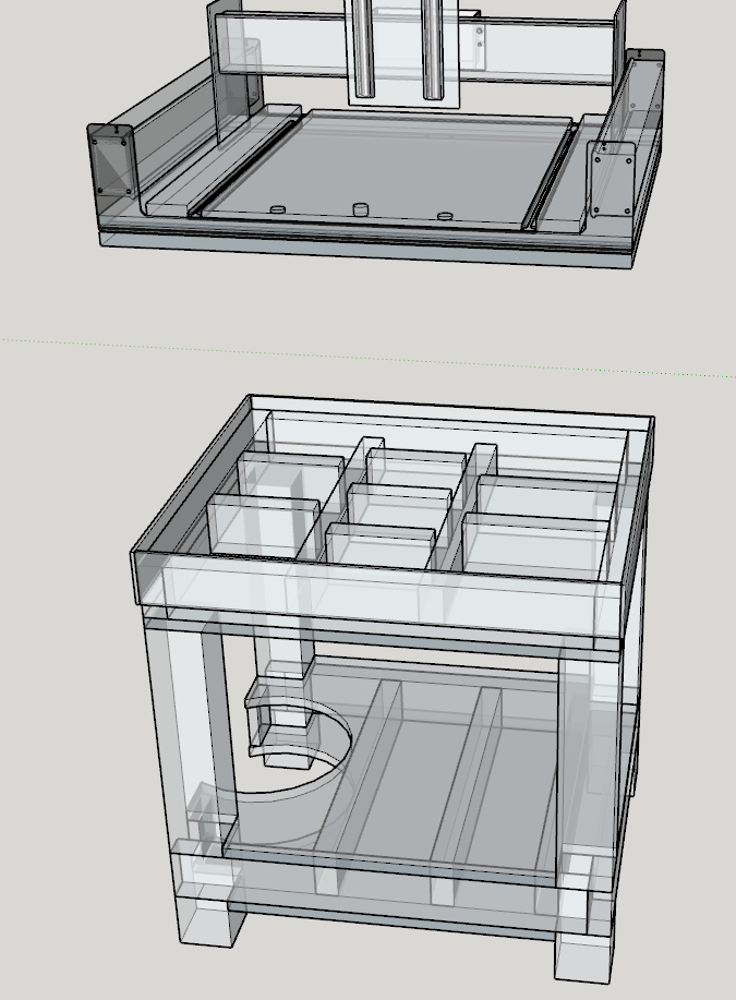
I started with a 3d model of the S3 (I didn’t model this - however the model is available to download for free from A360. It even has all the appropriate slider joints built in so all the axis can be moved to their respective limits.) and decided on a 30" x 30" footprint. It stands 36" tall (exclusive of the casters). The torsion top features 2-3-2-3 gussets longitudinally and 3 full-length transverse stiffeners. The torsion top frame is designed with off-the-shelf 1x4s in mind - only a chop saw, accurate measuring and final end-match sanding required. The top and bottom of the table can either be 3/4" MDF, or a 3/4" high-quality sanded ply. The rest of the construction is 2x4s, 4x4s and an additional sheet of ply for a shelf. Kreg normal and HD pocket holes and wood glue will provide the means of construction.

Ok, so I had completed the first design iteration. Time to build it, right? Wrong - time for static stress and modal analysis! (With all the great resources that Fusion 360 offers, why not, right?) Disclaimer: Fusion 360 did not accept my pine/plywood construction for my materials, but did offer an MDF option - close enough.

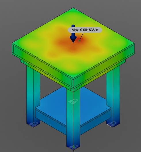
On with the stress analysis. 500lbs point-loaded at dead center of the table. Less than 0.002" deflection under 500lb load? Good enough in my book. Fusion 360 actually had the nerve on the results page to mention that the design is over-engineered, and costs could be reduced by optimizing the design or choosing less expensive materials - what sort of nonsense is that?

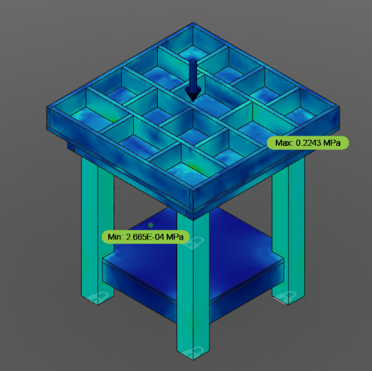
The Von Mises stress plot (I hid the top for clarity) shows the gussets doing their job and that the load is properly traveling through the vertical legs. Safety factor through the roof.

So I’ve proven it’s strong enough. Now what about those pesky resonant frequencies? I set a 70lb pre-load on the top deck and ran the analysis from 15000-28000 rpm, which is just outside the operating parameters of the Dewalt 611 router. The resonant frequencies within this range are excited by the following motor speeds:

  • 16752 pm
  • 16932 rpm (very close to speed 2)
  • 17298 rpm
  • 17328 rpm
  • 18432 rpm
  • 19170 rpm (very close to speed 3)
  • 19524 rpm
  • 19584 rpm

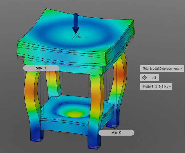
Since all the other motor speeds aren’t close to any of the above speeds, I can dismiss them from concern. Looking at the visual (exaggerated for clarity) results for modal potentials around router speeds 2/3:

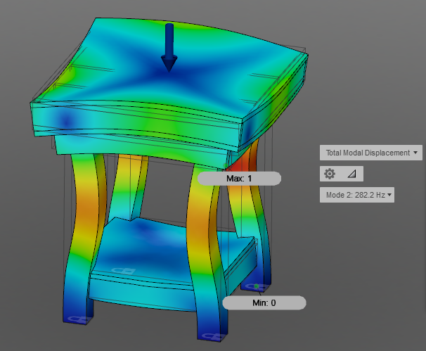
The more interesting results are at speed 3 - where the table top and bottom shelf essentially become passive loudspeakers.

Additional stiffeners were added on the vertical leg mid-spans, and one longitudinal stiffener was added under the bottom shelf. Analysis re-run.

A pretty solid loudspeaker effect is present at 17232 and 18246 rpm, which is in between router speeds 2 and 3 (it could resonate very briefly as the motor ramps up to operating speed).

Better, but let’s add 2 more transverse gussets and a 3/4" bottom skin to the shelf. It looks small because it’s a model, but the bottom board is 22" end to end - so think 19" speaker surface. This was actually my fourth iteration - the third didn’t include the bottom skin.

This scenario doesn’t occur until 21714 rpm, which will occur very briefly in between speeds 4 and 5 while ramping up.

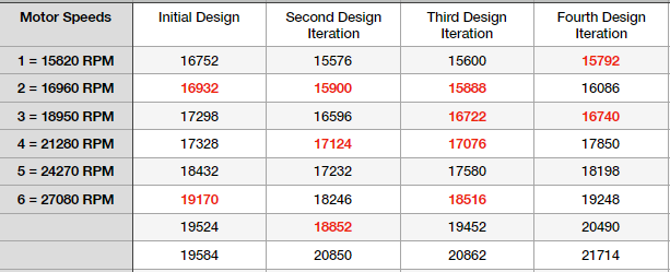
From the table, we see that the two most likely speeds that will resonate the bench are 1 and 2. In the results, these vibrations are translated through the bench legs and cross braces, but the table surfaces are relatively isolated. I’m not 100% happy with it, but this is good enough - also note that all of these designs assume that the Shakeoko is rigidly mounted to the bench top. I will likely isolate the Shapeoko from the tabletop with a damper of some sort.

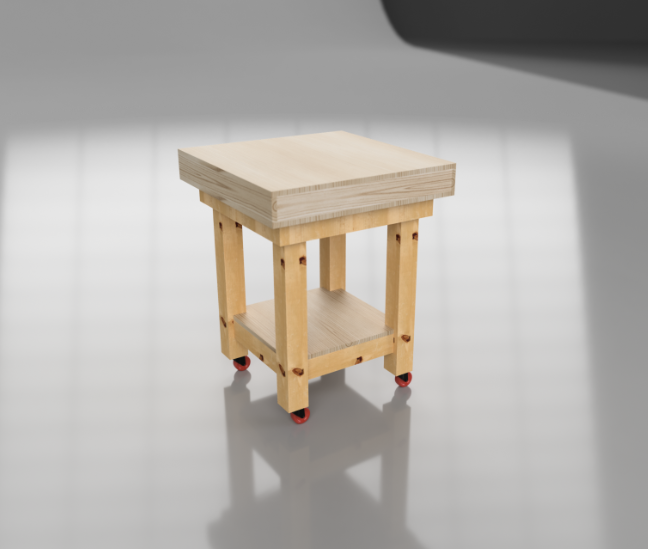
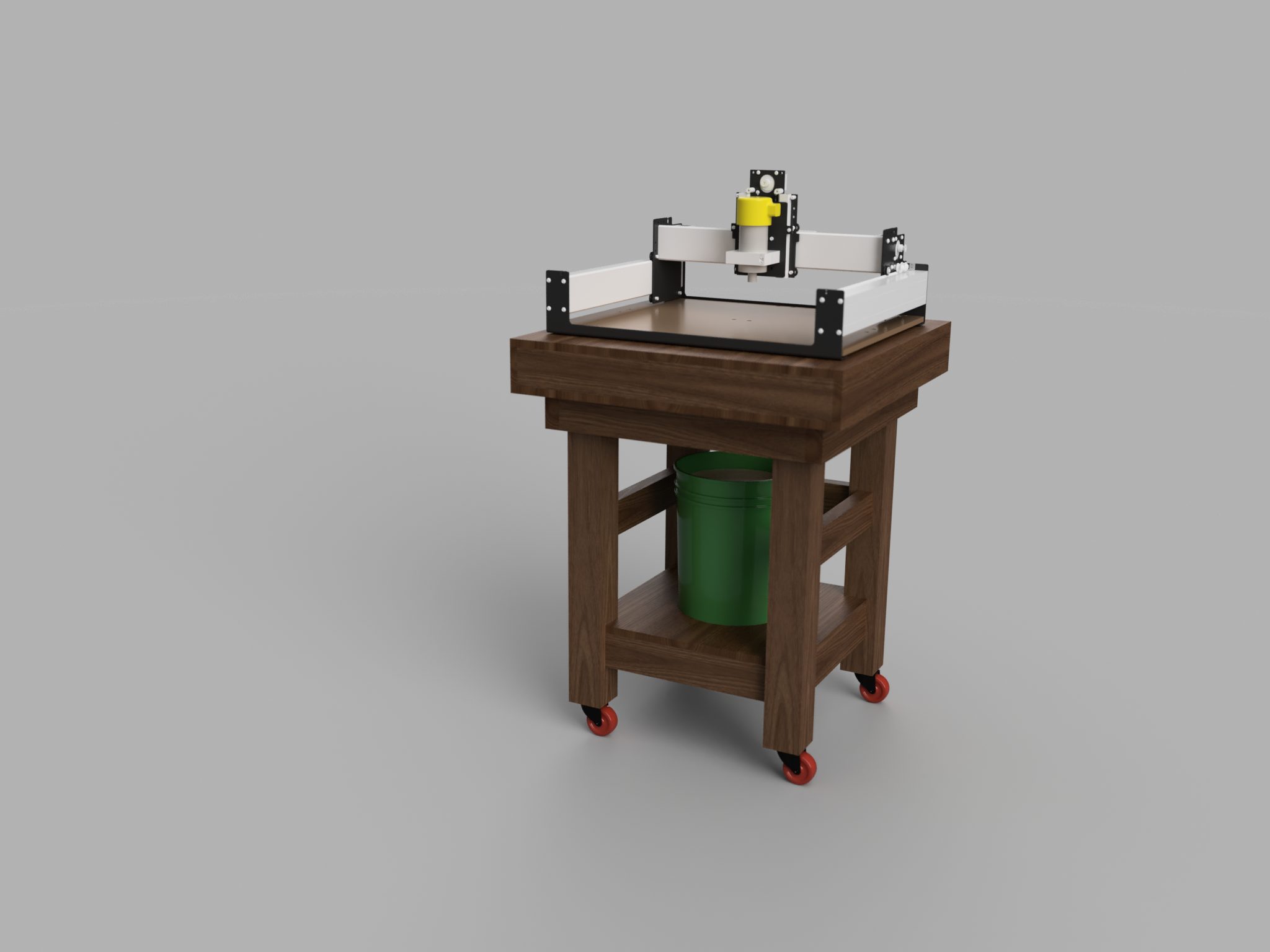
And the final (for now) revision in it’s mahogany-stained, rendered glory!

Still to do:

  • Design sound-attenuating enclosure
  • Design a fold-out laptop shelf on the side
  • Work out dust collection system (bucket shown for space-concept)
  • Make a fab drawing + BOM
  • Get off the computer and build the damn thing
  • Document the build
  • Build the Shapeoko

Once I’ve completed the drawing and take-off, I’ll post up the plans for use if anyone would like them. Thoughts on the overall design?

9 Likes

That design looks very clean, and the torsion box looks excellent :+1:

The FEA on fusion is great, and the software is free!

Dust collection - Look at the dust deputy by oneida, or something similar to that. I have one and it knocks out 99% of the dust into a 20 litre drum, then the rest goes through a Hepa filter in my festool dust extractor… quiet and clean!

I also highly recommend the Suckit Dustboot, its a great design and doesn’t move up and down with the Z-Axis, so works very well. In saying that… I think I will reverse engineer mine and make my own, more for the exercise than any other reason.

Do you have any initial projects you are aiming for?

What are you planning to use for software? The included Carbide Create is good software for 2.5D jobs, and Fusion360 has quite a powerful CAM package in it, which you are no doubt aware of. I very highly recommend the Vectric line of software, I use it and F360 depending on the application.

Look forward to seeing your progress!

1 Like

Thanks for the feedback and the tips. Fusion is excellent - I still can’t believe it’s free. I’ve been looking at the vortex-style separators - will have to find a way to stuff it in my design somehow. I’ll have to look at the Suckit boot for any wood/composite work.

For brass/aluminum work, I think I’d prefer to use compressed air for chip-clearing and cutter cooling. Then clean up later. I’ve never dry-cut aluminum but used to dry-cut stainless with only an air-blast and trichoidal milling when I used to work with industrial CNCs.

I have some motorcycle parts I’ve been designing that I’ll likely fab out of brass (foot boards, shifter/brake mechanisms, K&N air filter covers, intake manifolds, carb mounts, etc.) and some more artistic wood-working projects in the works. Maybe some carbon fiber drone parts.

I will likely use Fusion 360 for everything that I can. I haven’t used it for CAM, but I am quite familiar with HSMWorks (which Autodesk bought out and incorporated into F360). The Create looks good for simpler jobs and I look forward to trying it out as well. I have looked at the Vectric line, but I am partial to Autodesk products - I’m leaning more towards an ArtCam license. For less than $200 for the first year - and I’m horrible at learning new GUIs and workflows. It’s nice to have the continuity with the same developers.

Definitely excited to dive into the world of CAM again - this time for fun!

What if you filled the top torsion box with cement along with the bottom box (shelf)? Would that mass absorb the bulk of the resonances and for only a few bucks? Or even spray foam but the cement would provide both mass and weight which are both anti-resonance compatible? I love the dedication for completeness in your design effort and your inclination that a design can always be improved and accessorized. Why have a computer if all you do is play games on it, major kudos to you. Hope you the best in all you do. My machine sits on a poured concrete work bench and I think it is much quieter than any of the videos I’ve seen, One more question: What if you added a piece of sheet rubber (shower pan liner at Home Depot) between the parts before joining, decoupling the joint members to eliminate frequency transmission through the frame members and also MLV between the plywood and frame members. I made my own MLV using alum flashing and this sheet rubber, it was helpful and added about 20 decibles reduction to my enclosure. See how that works in your analysis efforts, I;d love to see those results. Terrific job with the modeling. Jude

1 Like

What a way to show off! and I love it! Congratulations on the Shapeoko, and thanks for whetting my appetite on what F360 can do-with someone who knows how to direct/ask it for it! I am just starting with it…not overwhelmed, but excited! Way back when, I went to Milpitas as a dealer for Autocad 10, but other than file extensions, there ain’t a whole lot I recognize!
Can’t wait to see what you do!

You can have that again pretty cheap and easy! https://youtu.be/ORJ-Q3TFW5o

2 Likes

Thats a good idea.
I watched a 12 hr video of a guy turning a cheapo drill press into a mill by filling the column up with concrete.
Thats not all he did to it, but the concrete worked.
I used to rent DIY, and machining videos from Smartflix, but I guess they’re gone, now :frowning:
Dang! I was going to learn some more stuff someday!
This was a most awesome wright up on the resonance issues.
Thats Great software.

1 Like

Rigidity, mass and cubic inches,…there are no substitutes!

2 Likes

Hands down the most comprehensive and thorough Shapeoko table design ever (that I have seen)… F360 has been on my radar for months and your write up illustrates just how incredibly power it is.

I have a newly acquired 3D printer, so it’s time to roll-up sleeves and get to it. Thanks for sharing this great write up and design, and I’m looking forward to future updates.

2 Likes

I’m an engineer as well, and outside of the torsion box that’s a very similar setup to mine. 2x4" frame, 3/4" plywood top and shelf, 4x4" legs. I have a single 2x4" runner down the middle (no torsion box, but it’s pretty quiet as-is. I could always throw more wood at it?), and my machine sits on 3/4" of foam with no leveling feet. I shimmed up the end plates to match the height of the straps, but on a 16" SO3 those don’t matter the same way. For the bucket you show in your images I actually cut a round hole in the bottom shelf to hold it so I would have clearance for my Dust Deputy and hose connections:

In same thread above look at what Jude did with his standard 16" SO3, it’s pretty slick!

Dan

2 Likes

Ohh there’s the hook!!! Thanks Dan, I’m caught, hook line & sinker… now I have to build a new stand for mine just to prove to me that I can do it better than last time. I got everything I need except the time and space. Maybe “Yoman” can help me with the " time & space " part, not to be too treky.

2 Likes

I’ll see about rounding up my spare portable hole and sending it to you…there is more than enough time and space in it! Lots of cool fresh water too, but it’s dehydrated!

1 Like

Appreciate the kind words. On the concrete, actually,I hadn’t - I had ruled out concrete or steel to not violate the mobility requirement. That being said, it’ll be on casters - it’s not like I’ll have to lift it, right?

Think I’ll run another couple sims with portland cement fill and marine-grade expanding foam fill. Should be interesting - thanks pushing fourth the idea!

I do intend on topping the bench with 1/8" or 1/4" medium durometer neoprene rubber (McMaster sells it by the foot), although I hadn’t thought that dampers between the members would be much use on something of this scale. Sounds like another sim is needed - it might not be possible/accurate since I don’t think rubber behaves linearly, but it’s worth a shot.

1 Like

Thanks - F360 is great. Wasn’t a big fan of it at first, but the more I use it I appreciate what they’re doing at Autodesk. I think the jointing method could be a bit more intuitive, but it makes sense of you don’t overthink it. I always thought Solidworks or Inventor was like legos for adults, but I think F360 nailed the lego part with their top-down design philosophy. The whole t-spline thing to me is foreign, but the potential to create some really organic shapes are endless.

Thanks for the link. I hadn’t seen that one but have seen another few with guys using HSM techniques on the Shapeoko. That was one of the selling points for me. I’m a huge fan of full-depth cutting when feasible.[quote=“YoMan, post:5, topic:5839, full:true”]
What a way to show off! and I love it! Congratulations on the Shapeoko, and thanks for whetting my appetite on what F360 can do-with someone who knows how to direct/ask it for it! I am just starting with it…not overwhelmed, but excited! Way back when, I went to Milpitas as a dealer for Autocad 10, but other than file extensions, there ain’t a whole lot I recognize!
Can’t wait to see what you do!

Which one did you get? I’ve been on the fence whether or not I would get much use out of one.

I have this idea that I may mess around with - if I have the enclosure on it air tight, then bore large holes on the sides and fill with PVC. Run some hoses into a manifold straight to the vortex/vacuum setup. Compressed air would chip-clear and push everything to the sides where the vacuum would evacuate.

This is definitely a round two sort of deal! I like his setup - wish I had that much space.

here’s my next stand,


I like self leveling cement in the top than It’ll be level for the shapeoko 3 to sit on, which is on it’s own 3/4" base. I did find my homemade MLV to work for sound reduction, before 101 d’s and after 81 d’s. So i’ll have it under the machine’s base on top of the SLC and also above the shelf’s concrete, yes both filled w/ concrete. I love overkill. Will need the BIG casters. there is a “lip” around the top exterior for the SLC to flow up to than I’ll remove the lip. Like the hole for the bucket at the edge not the middle, more room for the drawer case. and vacuum can get to it from the side. probably my contorted “thein” separator. Love to see the sim’s results. Thanks, who does sims for a stand??? We do, or YOU do, but glad you do! Oh yeah, there’s lots of comments about the dirchlet effect in here, “drum effect” vibration occelation or resonancability or something like that, cross members unevenly spaced and multiples are the best. Search dirchlet (sp?) in the forum. Jude ps homemade MLV is aluminum flashing w shower pan liner glued to it on both sides, (had leftovers of both). also I had the neoprene rubber under my machine and the pem nuts on the botton did not sink into it evenly, and when I removed the neoprene I did not hear any difference, so I doubt it was worth having in the 1st place, just my opinion.

3 Likes

Love it LOL, my Dad always saved an empty box in the garage, Mom would ask what;s in there, He’d tell her it’s full of post holes and maybe she can sell them to her friends.

If you’re referring to my setup, be careful what you wish for… my shop is 9ft X 15ft with 14 machines in it, 2 people can fit in there if the door is open, but I don;t invite anyone in my work shop anyways. It works for me fine, but I have to use every inch of every horizontal surface, above, under and hanging off the side. the bench top machines are under the table saw and I sit to use them (folding chair). Thanks though, Jude

1 Like

I was a Kickstarter backer for the Robo R2. I’ve only run test prints, but so far it’s been an outstanding user experience. I didn’t want to do a lot of fiddling with my first printer and extruder. The only issue I’ve had is the touch screen sensitivity (or lack thereof I should say). I’m gonna reach out to their tech folks and see what they suggest.

Very nice–opens my eyes what can be done. For many years, sand was used to deaden load speaker enclosures, and today shot is used for dead blow hammers. Just a thought.

1 Like