This looks like a great mod, thanks for the write-up.
I think I might have to buy one of these.
This looks like a great mod, thanks for the write-up.
I think I might have to buy one of these.
what rod and ball screw diameters are used?
I don’t see the exact dimensions of the screw on the website. You could ask Joe - cnc4newbie@gmail.com
Yes!!! I planed on retro fitting one of these onto my s3 but now that know he can make them setup for it I’m going to buy one for my standard and my xxl !!
You made my day
For sure… and if you want to see some additional exponentially larger forces just see what I’m running right now on the stock belt/wheels!! Note: No Z skipping even WITH STOCK Springs!!! I’m extremely impressed with it as of now and I firmly believe that there is something to having more mass to “suck up” some of the small issues on the machine with the default setup due to the inertia generated to keep things moving along smoothly. I thought about other upgrades as well, but when I ran my machine into my mounting bolt I broke 1 v-wheel… and not 5 other parts and bent part x & y  Weak links are like fuses made to stop the damage and might not be bad in cases like this!!!
oh and my machine!!! sorry:
Great job and nice write up!
It’s been a little over a week so… are you happy with it?
Ray
So far so good Ray. I forgot to put loctite on the grub screws for the coupler. So they both flew out. One I found immediately and the other I found the hard way when it wedged itself in between the extrusion and the carriage and caused me to lose X steps.I have since replaced the grub screws and used loctite this time. I just finished a pretty aggressive planing of a large uneven panel glue up (old warped 6" oak flooring planks) and it worked great. I’ve done a couple of carves since getting the new Z. I will post pics as soon as I can.
I am very happy with it so far. Thanks for checking out my post.
Got mine last night, but have yet to start trying to fit it. Noticed something though, on the newer X-axis plates with the pulley tensioner nub+screw, how is this supposed to clear that? Has anyone else given this a try? I did notice that they have revised the bottom mounting holes and made it just one hole, but with the tensioner nub in place I don’t see how this will fit unless I take my X axis plate to the grinder.
visual of nub:
Thanks,
Dan
Mine was a 2015 version that did not have the tensioner. I doubt they can make a hole big enough in the plate for that could they? I’d probably go ahead and grind it off unless you need to keep it on there for fallback purposes.
Very doubtful, it sticks out pretty far.
Yea, I’ve thought about that, but even though I’ve forked out the dough I’m not completely sold on this upgrade until I see it in action for a few hours(for reasons stated in my above replies). I really want it to work though, I wish there was a way to grind it off, but have it still be there for fallback reasons, haha!!! I sent a message to Joe, hoping I’ll hear something soonish.
Wonder if anyone has a 2015 plate they want to part with? @WillAdams , hypothetically speaking, if I were to destroy this plate does C3D sell it by itself? Just hypothetically of course, as in I don’t have this plate up against my grinding wheel, …just yet ![]()
Thanks,
Dan
While as a matter of policy we don’t sell à la carte parts, we will sell replacements to folks whose machine have damaged parts which need replacing.
Actually, on second look, it sticks out about 0.384" and the back plate on the Z slider is 0.375", so you could in fact mill a hole completely through and it would still miss the workings of the slider. The hole would have to be about 0.5" to clear, but I think there would still be enough material to hold the bottom single screw bolting the slider to the plate…it’d be awfully close though since the newer plate has a slot for the bottom/center hole instead of a straight hole. If I were to go that direction I’d rather have the earlier version of the slider with two holes at the bottom for security. I have a whole weekend to look at it though, and we have a Bridgeport mill at work that I have “some” access to so I could get that hole dead on.
Question, on your version of the slider, do the two bottom mounting holes also thread into the bottom screw holding plate? I wonder if on mine it would be a matter of boring a 1/2" hole, then removing the bottom plate screws, and using those threaded holes to mount the bottom? Any idea what the thread pitch is?
Thanks,
Dan
@DanoInTx I recommend you email Joe and see what he says. I’m assuming his testing was done with an older style plate like mine, so he will need to incorporate that hole in his design to accommodate all of the new plates. My package only came with M5 screws for mounting the slider and M4s for mounting the motor. I’m not sure what size Joe used for the bottom center hole. He is usually pretty fast to respond via email - cnc4newbie@gmail.com
I’ve contacted Joe and he has replied, apparently I’m the first with this issue, so I’m going to take some measurements and send them to him so he can accommodate the adjuster nub. We’ll see how it goes.
Thanks,
Dan
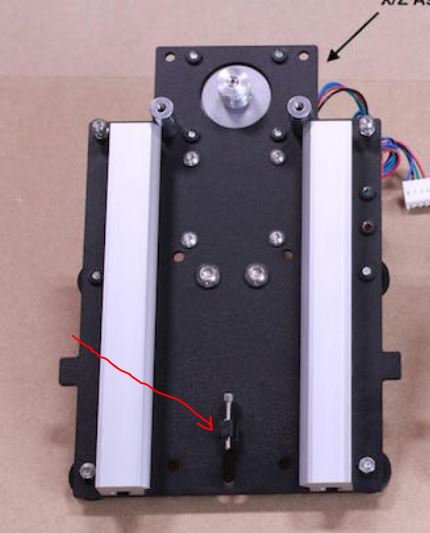
Small update. I’ve just discovered in addition to the adjustment nub there’s also a clash with the four PEM nuts used to hold the stock Z stepper motor in place. On earlier versions I suspect because belt adjustments were made by lifting the stepper they didn’t have these permanent nuts @dtilton71 can you confirm?
Thanks,
Dan
Not on my Z plate. I have a picture above of my plate prior to installing the new slider. Mine does not have PEM nuts there, just holes. I can see the PEMs you are referring to in your photo above.
I never thought I’d be so happy to have the old plate.
Also definitely worth mentioning, Joe at CNC4NEWB’s is really quick to respond to emails and is already planning to correct these issues for folks with later model X plates like mine, great customer service!!!
Yep, I didn’t think so, mostly because there is no way to move the stepper for belt adjustment on the current plate, thanks for confirming. Funny, I didn’t even think to look at your pictures above, I’m getting so blind these days I doubt I’d be able to pick those tiny PEM nuts out unless you zoomed way in.
Thanks,
Dan
HI,
Just finished this upgrade on a XL (that was converted from a standard S3).
Fit and finish was perfect, no physical anomalies at all.
However, I do have a travel issue I am hoping someone can advise me on. The Z axis moves up and down easily and cleanly but Only 4" in total. It does not matter what I set $132= to, any number from 5 to 800 has No effect on the total travel I get when jogging. (machine is usable with this much travel, I would just like to set my router higher in the clamp)
Ive read as many posts as I can find, but cant seem to figure this out. For example, I turn on cnc, start up carbide motion, home, open the send panel and type exactly $132=199
When I send, then open log and use $$ to list, I see that $132 does indeed equal 199.
However the total distance I can jog the Z azis remains the same, if I use 199 or 5, it still travels 4" down from the home limit positon.
GRBL on the carbide board is.9g and below is my latest list - any suggestions/advice much appreciated…
Thank You,
Peter
Test Waiting…
<Idle,MPos:-4.550,-18.500,-45.500,WPos:-4.550,-18.500,-45.500,Buf:0,RX:0,Ln:0,F:0.>
gc_not_motion
___________$$ ___________
$0=10 (step pulse, usec)
$1=255 (step idle delay, msec)
$2=0 (step port invert mask:00000000)
$3=2 (dir port invert mask:00000010)
$4=0 (step enable invert, bool)
$5=0 (limit pins invert, bool)
$6=0 (probe pin invert, bool)
$10=255 (status report mask:11111111)
$11=0.020 (junction deviation, mm)
$12=0.010 (arc tolerance, mm)
$13=0 (report inches, bool)
$14=1 (auto start, bool)
$20=0 (soft limits, bool)
$21=0 (hard limits, bool)
$22=1 (homing cycle, bool)
$23=0 (homing dir invert mask:00000000)
$24=100.000 (homing feed, mm/min)
$25=1000.000 (homing seek, mm/min)
$26=25 (homing debounce, msec)
$27=5.000 (homing pull-off, mm)
$100=40.000 (x, step/mm)
$101=40.000 (y, step/mm)
$102=200.000 (z, step/mm)
$110=5000.000 (x max rate, mm/min)
$111=5000.000 (y max rate, mm/min)
$112=5000.000 (z max rate, mm/min)
$120=400.000 (x accel, mm/sec^2)
$121=400.000 (y accel, mm/sec^2)
$122=400.000 (z accel, mm/sec^2)
$130=425.000 (x max travel, mm)
$131=465.000 (y max travel, mm)
$132=199.000 (z max travel, mm)
ok
gc_dwell
___________N0 G4P0.05 ___________
gc_get_offsets
___________$# ___________
[G54:0.000,0.000,0.000]
[G55:0.000,0.000,0.000]
[G56:0.000,0.000,0.000]
[G57:0.000,0.000,0.000]
[G58:0.000,0.000,0.000]
[G59:0.000,0.000,0.000]
[G28:0.000,0.000,0.000]
[G30:0.000,0.000,0.000]
[G92:0.000,0.000,0.000]
[TLO:0.000]
[PRB:0.000,0.000,0.000:0]
ok
gc_parser_state
___________$G ___________
[G1 G54 G17 G21 G90 G94 M0 M5 M9 T0 F100. S0.]
ok
<Idle,MPos:-4.550,-18.500,-45.500,WPos:-4.550,-18.500,-45.500,Buf:0,RX:0,Ln:0,F:0.>
I don’t see anything that would limit your Z travel. Your steps/mm are set to 200 ($102). I see your $13 is set to 0, so you are not reporting in inches, but that must means you are reporting in mm, should not be limiting anything. Your hard limits are not turned on $21=0, so I’m not sure how your homing works, but I guess I’ve never tried homing with $21=0; If you have an XL, shouldn’t your $130 be more like 840 or 850 (not that it would affect your Z travel). I’m not the GRBL expert by any means, but I don’t see anything that would be limiting your Z travel. Hopefully someone smarter than me will be more helpful.