You changed a rapid move command to a feed rate move command.
Looks like the problem is It has the rapid move command, with no Axis, or distance afterwords.
EDIT: The Zed height is in line 3 (.5mm)
There should be an F word before that line, too, so G1 knows how fast to move.
For instance maybe:
G0 1
G1Z-0.25 ???
G0 1 = Move rapidly to 1 mm above, then next line is
G1 Z -0.25 = Move at selected feedrate to -0.25mm
After the M3 line you should have an F word that will control the G1 moves.
One thing that helped me learn G code the most, was that it doesn’t have to be in any specific order (usually), as long as all the codes are on a line Before any moves.
Anything in () is just for humans to read, and is ignored.
Your code starts telling the machine:
%= begin (Start or end of program)
G21= METRIC moves
G90= Moves are absolute coordinates
M6= change to tool
T9= Tool #9
M3= turn spindle on clockwise
S 1200= spindle rpm 1200
F= how fast to move with G1 commands(probably covered by the red arrow)
G0 = MOVE AS FAST AS IT CAN
@kdur
You shouldn’t have to tweek the code from CC. It was made for this machine
I believe the above quote would fix this issue, and it’s one you’ll pay attention to a lot.
I Hate waiting for long slow plunges!
But be Careful. I’ve also been known to crash into a few clamps here and there.
It’s supposed to be higher than your clamps, but I try to keep them out of the way. Doesn’ always work that way.
I used tape on plexiglass, and table, then super glued them together last night.
It worked good.
There is a good section in the Wiki on work holding.
The code in the picture is the code generated by CC. I was trying to do what WillAdams said a few comments up in this thread. I was under the impression this would change the rate at which Z drops on the initial after hitting begin project. Changing the 'retract height" in CC doesn’t change the initial rate of speed on the Z. Hope that makes sense!
I understood, but what I was trying to say is the retract height setting should also change the speed.
It should move fast to the height specified, then slow down to the feed rate.
What comes after the G0 behind the red arrow?
In your code, after the M3 line, is there a feed specified for G1?
Where it says: G1Z-0.25 (big red arrow)?
There needs to be one.
It looks like there is one on the next line under the arrow, maybe, otherwise it must be a slow plunge somewhere else in the code?
The G1Z-0.25 should have your plunge feed after it.
My retract height setting only works once the cutting has begun and I move from toolpath to toolpath. I have it set at 1mm. Changing it does nothing to the intial plunge.
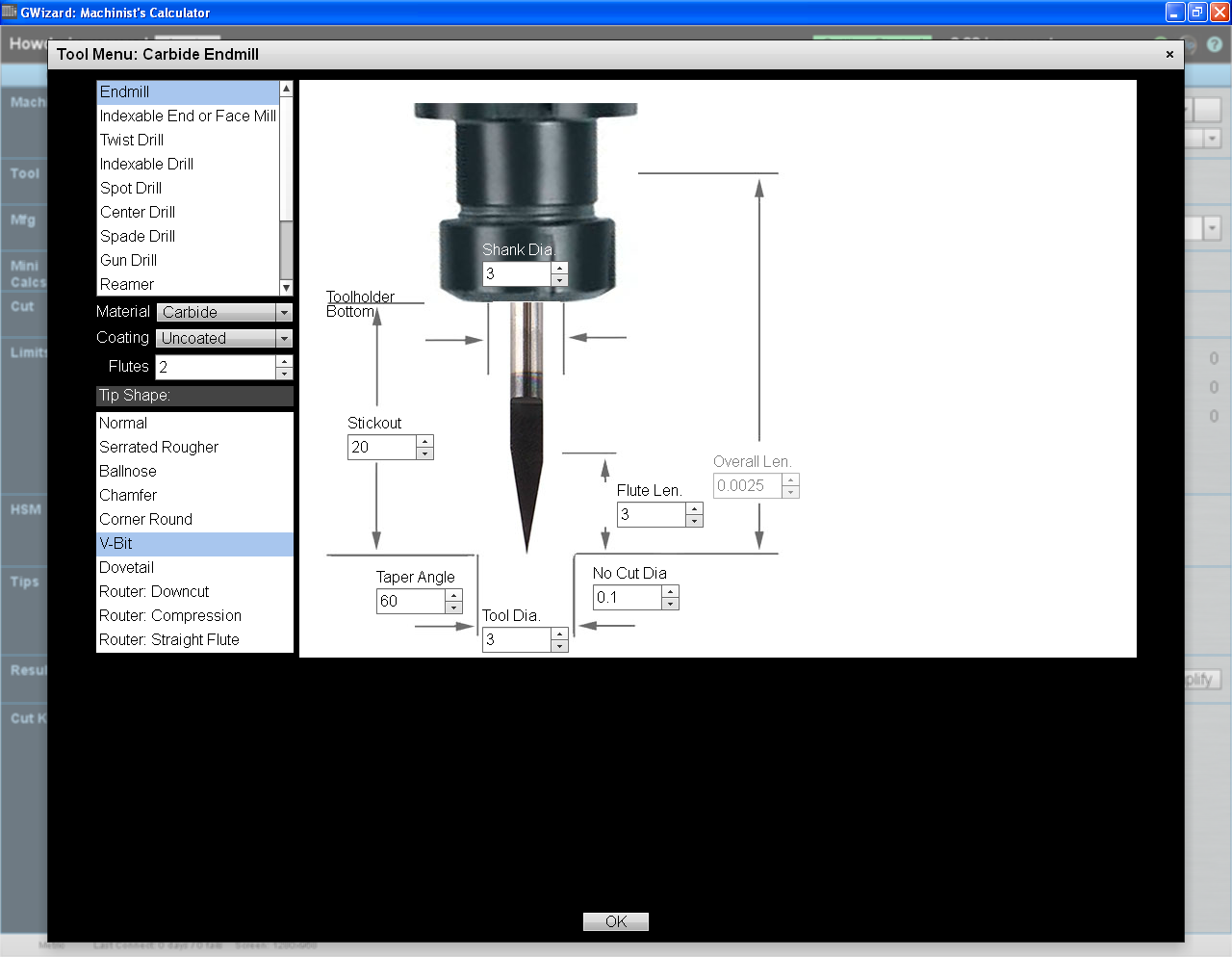
Here’s what I got using GWizard.
I had to guess a little about your tool parameters.
Stick out is important, and 30 Deg in CC is 60 Deg in GW (I think I saw that somewhere),
So if the first Pic is close, then so should the second one
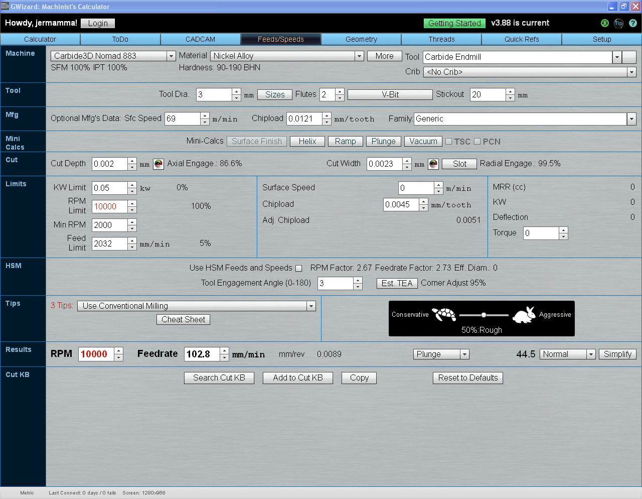
In the next picture the red just means that we could go faster if we could.
Towards the bottom is your answers.
Anything you need me to change I will.
The MFG and MINI CALCS section can be ignored.
If that works good, and you want to try, I think you could go deeper passes.
I dont do micro machining, under 1.5mm yet, but .002mm?
I moved the slider all the way to Turtle and rabbit, and the settings never changed, meaning that there is no load, or deflection at that depth and speed on the cutter.
I get the same answer for .5mm depth of cut, but in the middle, over the rabbit (in the limits section), You can see tool deflection, Material removal rate, and Kw usage, starting to factor in.
No warnings yet.
Tool deflection should be good up to here 0.0254mm. We’re only at .002258
I can try and see if that helps. The tiny cutters snap almost immediately once they touch the metal. I thought I could do a pocket cut with a .007 on small letters.
With these tiny cutters, I believe your spindle should be maxed out.
I think thats a lot of why your breaking them. Too slow rpm to feed, maybe. Plus if they turn too slow they rub instead of cut, then break, even if the rpm and chipload equal what you want.
Babying mills can break em too.
Of course I’m not the one buying the End mills, so it’s easy for me to guess
But I do use this @ 45% rough. Thats been working good for me.
I have it turned all the way down for you, so I HOPE it’s safe feeds.
I noticed you ran your RPMs way slow for those diameter cutters.
For instance the example above wants
33000 RPM
339 FEED
147 PLUNGE
The chipload is the same.
If the RPMs are too fast the cutter wont usually snap right away. It gets too hot and burns up first, then breaks.
If it snaps right away, the rpm was too slow for the feed, or just too slow.
Regarding the wax, you want to melt a blob that goes under the majority (or even all) of your stock to produce a thin uniform seal. Use a heat gun on low setting to melt the wax, and wiggle the material as you’re applying pressure to mount it to the plate to squeeze out bubbles and extra wax to ensure it’s uniform underneath.
While Will’s ideas of using Super77 or a vacuum table aren’t bad, there are side consequences for that—namely the work to clean-off the adhesive or the work of creating a vacuum setup, which is a whole project to itself!
In reading about the challenges you’re having with the engraving cutters, I’d recommend trying either straight or spiral pyramid tools, which are like engraving tools but have 3 cutting edges instead of just one and are much sturdier, or tapered ball end mills because the engraving cutters are generally meant for softer materials, especially at those really small feature sizes. Bitsbits.com has some good tools, and you can easily order online. They frequently have ‘surplus specials’ which are a great way to pick up tools inexpensively.
I would recommend that you use the widest angle cutter you can, because the wider the angle the stronger the tool—so if you want 0.007"deep by 0.007" wide letters, you could use a 60° included angle cutter and be far less likely to break the tool than if you use a ‘skinnier’ tool.
Rather than monkeying with the G-code directly to rapidly move into position for cutting, I’d recommend using a CAM system where you can edit those variables in the CAM process, just to make sure your simulations and your actual cut paths are going to match up. Personally I’d recommend Fusion360 from Autodesk because it’s free/cheap depending on your usage type (hobbyist vs. student vs. professional).
There are also a lot of YouTube video tutorials and such on how to use Fusion online. Good luck!