$100 Cash bounty: Can't figure out why my diamond engraver is making inconsistent textures

My guesses

You may have chipped the diamond check it under magnification

try lubrication on a piece perhaps it’s somehow galling

What Z axis are you using stock?

2 Likes

I should have mentioned that I’ve both inspected the bit under a microscope and tried a different bit with no change. It’s the stock z axis.

Both ways, but on reviewing the video I took I can see it creates both ‘colors’ while dragging in the same direction.

definitely inconsistent pressure of some sort and with such little room for error a screw driven Z may be necessary.

have you tried facing the stock before engraving? When was the last time you faced your waste board?

I do wonder if you could sandwich a piece of borosilicate glass under the copper without breaking it that would give a hard flat base to engrave on. Glass base face the copper then run a job.

1 Like

Why would the pressure be different at the bottom of each of the shapes though?

I don’t know much about engravers but in my experience surface finish problems usually are related to chip clearing. I’m not sure if that is even a thing with your engraver but it could explain the inconsistent nature of the problem.

I don’t know how good the extrusion tolerance of your stock is so facing a small piece and running a sample might be worth while.

you might also have a flat spot on a v wheel. Can you mark the X-Y orientation in the picture

Could it be something to do with parallax in viewing the reflections? With no visible difference with even balanced lighting, perhaps there is a lenticular* effect with the reflection under normal lighting.

  • I may be grossly misusing this concept. I’m thinking of those magic moving images that change with the angle you view them at.
2 Likes

Can you tell me a little something about your spindle/router?

Brand-name, model?

Could you inspect the different surface finishes with a microscope as well? That could be quite revealing.

Regarding the theory about pressure, I think we can test it like this:

  • Get a piece of stock (or a few pieces of stock)
  • Put the zero at some point on your machine such that you can reuse it a few times
  • For each depth between <normal depth ± 0.03mm>
    • Face ~20mmx20mm of the stock
    • Engrave ~15mmx15mm of the stock at depth

The intention here is to see if small deviations in the depth of cut lead to the effect you’re seeing. The reason we reuse the same zero is to try to eliminate variations in the axes of your machine. That’s also the reason why we face the stock each time, instead of facing it once.

1 Like

Is every line parallel and the same distance from its neighbour? It’s hard to see in the pictures but the patter does not appear to be regularly spaced.

One possibility is that the metal is beings scribed for some cuts, but deformed for others. So cutting a V shape into a flat surface gives one result. Scribing a V next to another V bends the metal on the existing V since it’s very thin, especially at the top. Or putting a V between two V’s bends both sides. Each then produces a different reflections.

5 Likes

@bellxone,

I might have missed it in this thread or the earlier one, but can you confirm you are using a spring-loaded diamond-drag bit ? 99.99% sure you do, but still asking.

Could it be a mechanical issue inside the DDB, I’m thinking some kind of grip inside the mechanism that would prevent a fully smooth movement of the bit along the Z axis.

I happen to have a spring-loaded DDB and some leftover brass plate from a cut, I’ll try to engrave a similar raster pattern and see what it does on my machine. Can you confirm the line spacing is around 0.004"?

3 Likes

Could the tip of the DDB not be perfectly circular? Maybe it has facets, and as it drags back and forth, it is rotating in the spring loaded body and creating the different scratch geometries? Maybe put a sharpie mark on the shaft of the bit itself and see if it is rotating.

4 Likes

So, I tried engraving a 20x20mm square using a raster pattern at 0.004" stepover, and 2mm depth/pressure on the DDB, in brass, at 40 ipm feedrate.

The engraved surface is mirror like and it was near impossible to catch a good snapshot that would not reflect various parts of my enclosure and its lighting, but basically the surface looks uniform when I observe it from various angles.

@bellxone, would you mind sharing a tiny sample of your G-code (that would for example be limited to a single “leaf”), for me to run that and see what happens? In your CAM, does the DDB move in a raster pattern between left and right, or always in the same direction ?

1 Like

definitely inconsistent pressure of some sort and with such little room for error a screw driven Z may be necessary.

I kind of doubt this explanation as I tried different depths varying by more than 0.1" which I don’t think produced anything like this dull effect. Seems unlikely a much smaller variation in depth produced by an error somewhere could produce it.

I don’t know much about engravers but in my experience surface finish problems usually are related to chip clearing.

I considered this, but that wouldn’t explain why the dull section always tends to be toward the bottom, or why it seems to be getting worse over subsequent jobs.

you might also have a flat spot on a v wheel. Can you mark the X-Y orientation in the picture
1: Right is bottom
2: Not sure
3: Left is bottom.
Again, hard to explain the bottom of these shapes usually being the dull part with a flat spot on the wheel.

Can you tell me a little something about your spindle/router? Brand-name, model?
It’s the Makita that Carbide3D sells.

Could you inspect the different surface finishes with a microscope as well? That could be quite revealing.

I did. Pictures in the first thread. I couldn’t discern anything from them.

The intention here is to see if small deviations in the depth of cut lead to the effect you’re seeing.
I tested this some time ago but can try again once I get my CAD machine fixed (I broke the partition somehow.)

Is every line parallel and the same distance from its neighbour? It’s hard to see in the pictures but the patter does not appear to be regularly spaced.
There’s some wobble in the lines if you look at the microscope photos in the first thread, but not a ton. The earlier jobs that didn’t have this problem don’t seem to be any straighter.

One possibility is that the metal is beings scribed for some cuts, but deformed for others. So cutting a V shape into a flat surface gives one result. Scribing a V next to another V bends the metal on the existing V since it’s very thin, especially at the top. Or putting a V between two V’s bends both sides. Each then produces a different reflections.

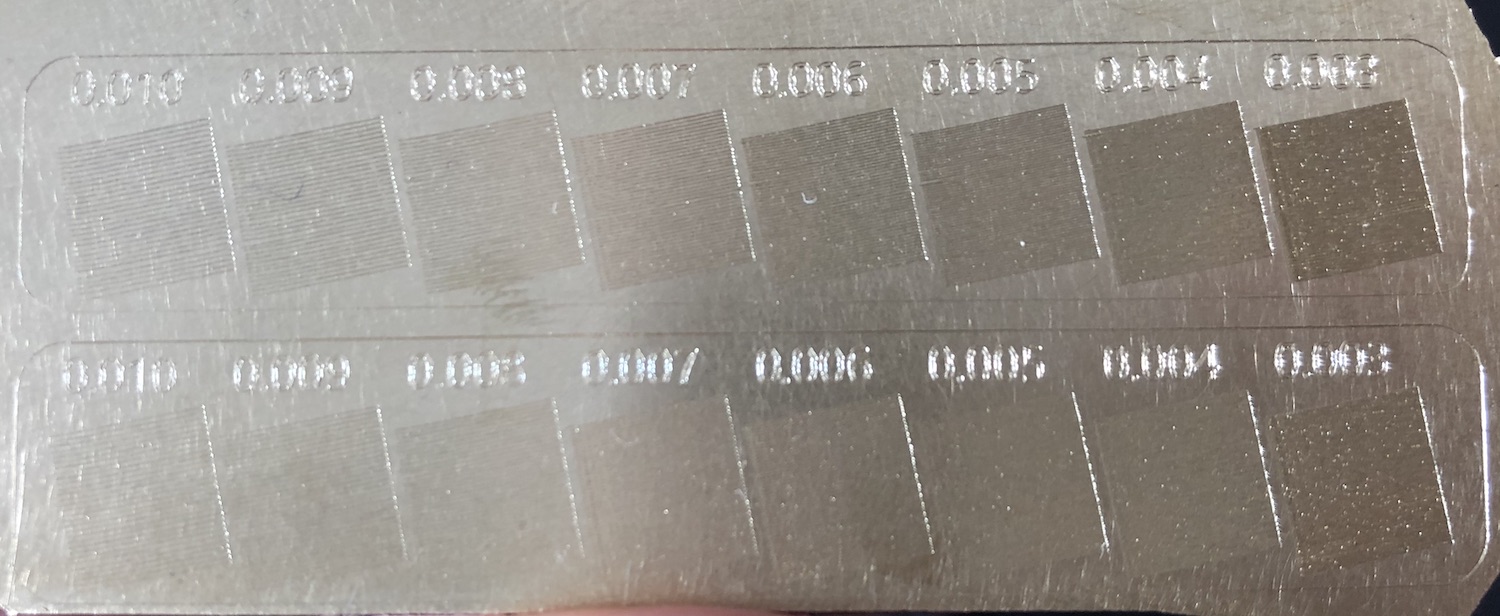
Interesting theory. I considered something like this, but still not sure why it would suddenly start happening… Maybe my pitch is too tight. These are around 3 thou between the center of each line. Once I fix my CAD machine I’ll try running some different pitches. The weird thing is I ran a piece with a bunch of different test pitches and none of them had this issue. See image:

I might have missed it in this thread or the earlier one, but can you confirm you are using a spring-loaded diamond-drag bit ? 99.99% sure you do, but still asking.

That’s right. I’ve tried a new bit too. Spacing is 0.003.

Could the tip of the DDB not be perfectly circular? Maybe it has facets, and as it drags back and forth, it is rotating in the spring loaded body and creating the different scratch geometries? Maybe put a sharpie mark on the shaft of the bit itself and see if it is rotating.

Already tried this with a piece of tap. Couldn’t see any rotation happening.

would you mind sharing a tiny sample of your G-code (that would for example be limited to a single “leaf”), for me to run that and see what happens?

To be honest not sure how to do this. The gcode file is 200k+ lines and the leaves aren’t done sequentially - it jumps between them.

In your CAM, does the DDB move in a raster pattern between left and right, or always in the same direction?

Usually the same direction but I think I’ve seen it go the other way too. I already checked to see if the dull spots were created by it traveling in a different direction from the bright spots, but that doesn’t seem to be the case.

1 Like

Interesting…I wonder if this might be a factor, especially considering your test piece at different pitches is clean. Is there any way you could force the CAM to engrave one leaf at a time, raster style, rather than jumping around and coming back ? At such a small pitch, tiny mechanical errors (backlash, slop, …) might introduce a tiny offset between one line and the next one engraved when the DDB comes back from somewhere else. It would be interesting to visualize the G-code, and see if the transition areas you are seeing match the rapids between.

Depends on your CAD file, you may be able to just select one leaf and apply the toolpath to that. I did not want to ask for the full G-code file or the full design file as I guess you would like to protect your artwork.

1 Like

I experienced that the GRBL controller (or the gcode sender) is sometimes not able to process the gcode fast enough and causes an unwanted slowdown of the feed when the machine path is very fragmented, i. e. when there are many many little movements in the gcode. The slowed feed rate could cause a different surface finish.

In Fusion 360, I always use tool path smoothing to avoid that. (No help for you I suppose…)

Maybe you check you gcode if it contains many small movements per ‘scratch’…

3 Likes

Not all spring loaded bit holders are of the same quality. I had to try a few to get consistent results.

Here’s one test you can do. Try engraving some circles of different diameters, especially small ones on the order of 2 or 3 mm. Are they well rounded? Does the engraved width vary?

3 Likes

I’m using Vectric Aspire for the actual path generation. I’m guessing it doesn’t have many options for determining the exact path generation but I’ll take a look.

I’m going to try carving some different patterns to see if I can learn anything.

This topic was automatically closed 30 days after the last reply. New replies are no longer allowed.