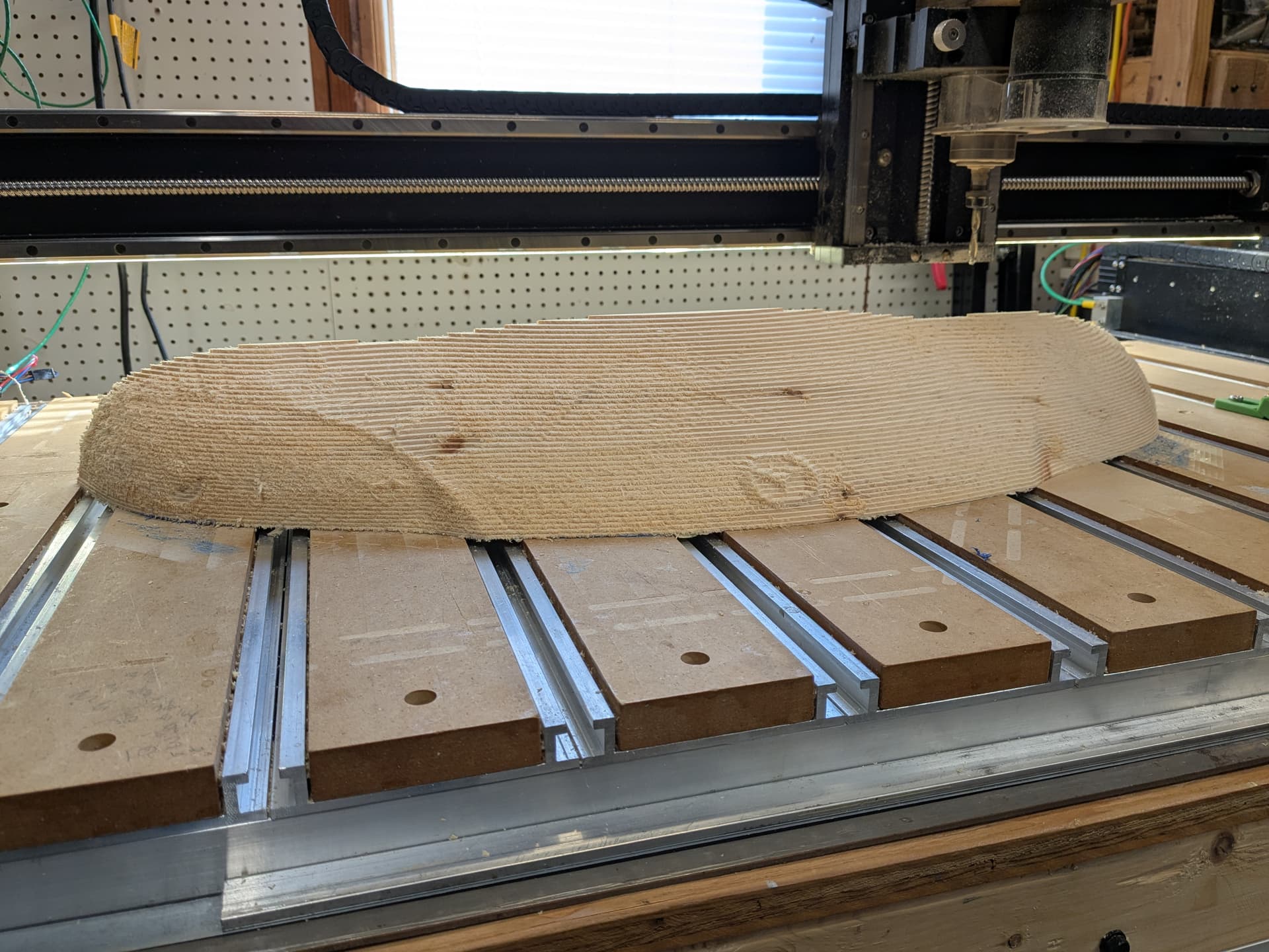
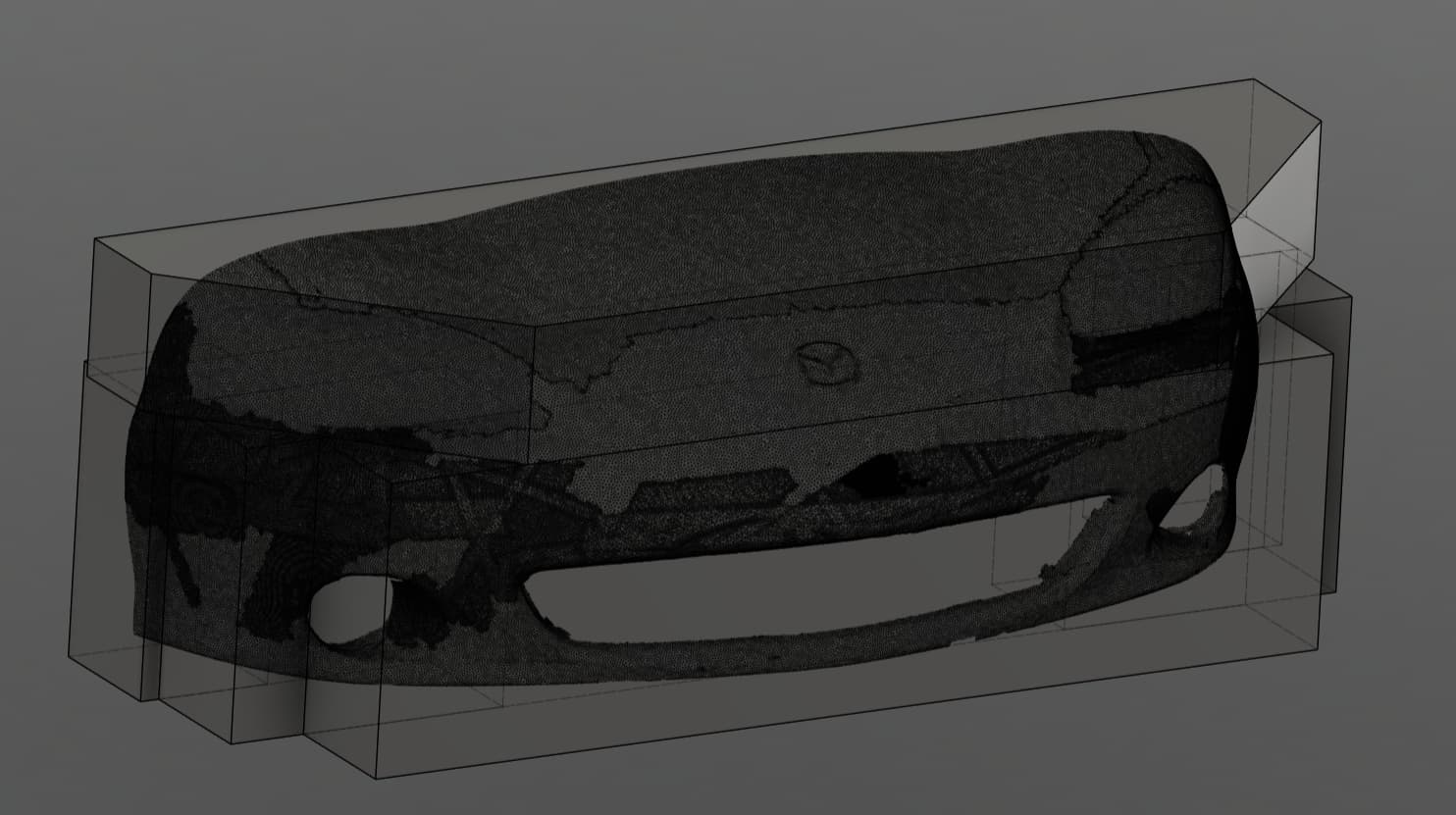
I am attempting to make a 1/2 scale replica of the nose of my wife’s Miata.
I laser scanned the nose.
I am using Eastern white pine because it was free.
There are a boatload of lessons I am encountering, but I will limit the question to a finish cut.
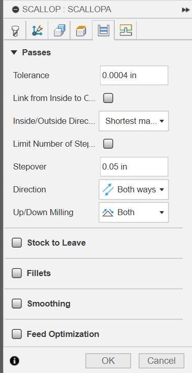
In Fusion I used a Scallop path for the finish with a 1/4 "Downtown Jenny. I used that because I had excellent results when I cut a Minnie doll.
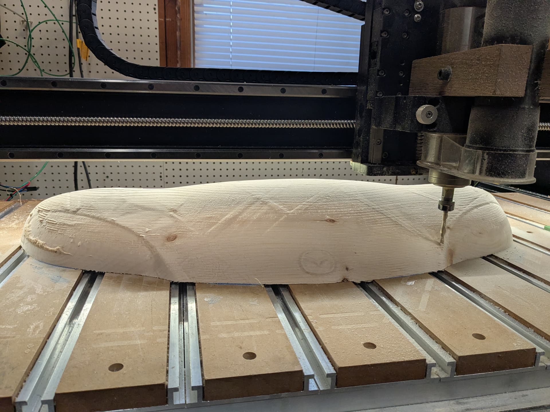
The results on the top plate was not nearly as good. The only really nice surface was 30 deg off of vertical at the headlight lens. I realized the Minnie cut was mostly vertical surfaces.
I have a 65 mm spindle so I can not use a big ball end mill.
What are your suggestions for cutting path technique to cut swoopy mostly horizontal surfaces ?
It looks like a Parallel path is my best bet, at least it seems better.
I realize the Pine will not smooth like a hardwood. Looks like I have to do some sanding.
I had a 97 Model 1 Miata. I loved that car. That car proved it is not the size of the dog in the fight but size of the fight in the dog. I wish I had never sold that car. Mazda Miata is a car with a lot of soul.
I bought that car in California and drove it back to Texas. I felt like I was riding on a skateboard all the way back. You sit very low to the ground and when 18 wheelers would pass me I felt very small. That car was a ton of fun. I would be going 90 miles an hour around flyovers that were marked for 45 MPH and if it had wings I would have been flying. Hopefully your wife obeys the speed limit. I usually do obey the speed limit but sometimes… My current sports car is a 2003 Ford Thunderbird. That car left the Miata in the dust and goes 140 miles an hour. Dont ask me how I know. But it is electronically limited to 140 and I have to buy Z rated tires in case somehow it goes 140. Although the T-Bird is fun I still miss my Miata.
We can it “the skateboard”. 2004 Mazdaspeed 6-speed manual.
Fun on New England side roads. Highway not so much.
I can go about an hour before my back says enough. Cheap to run and maintain.
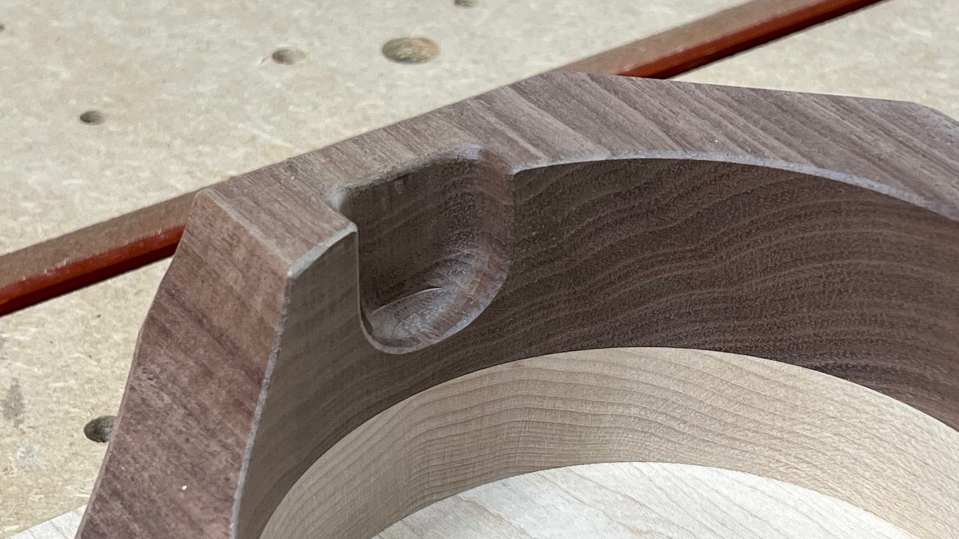
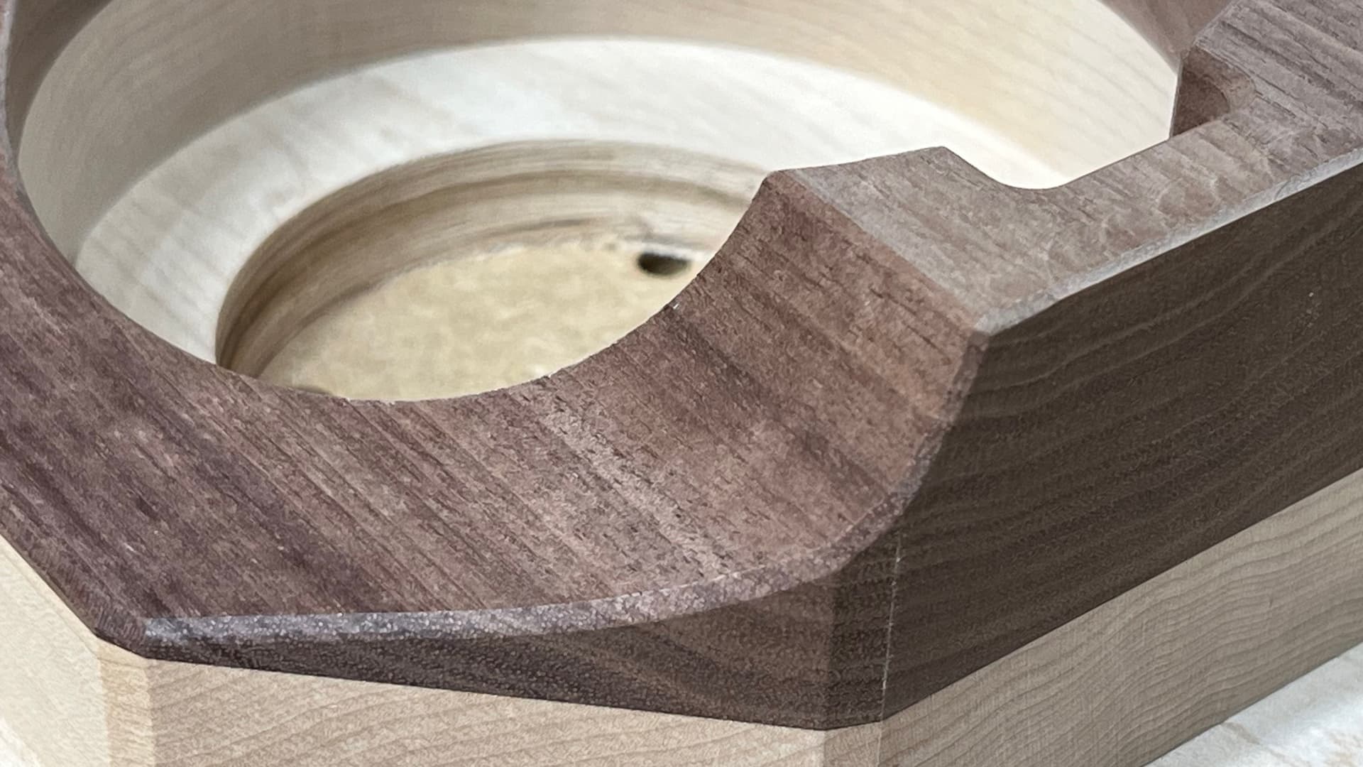
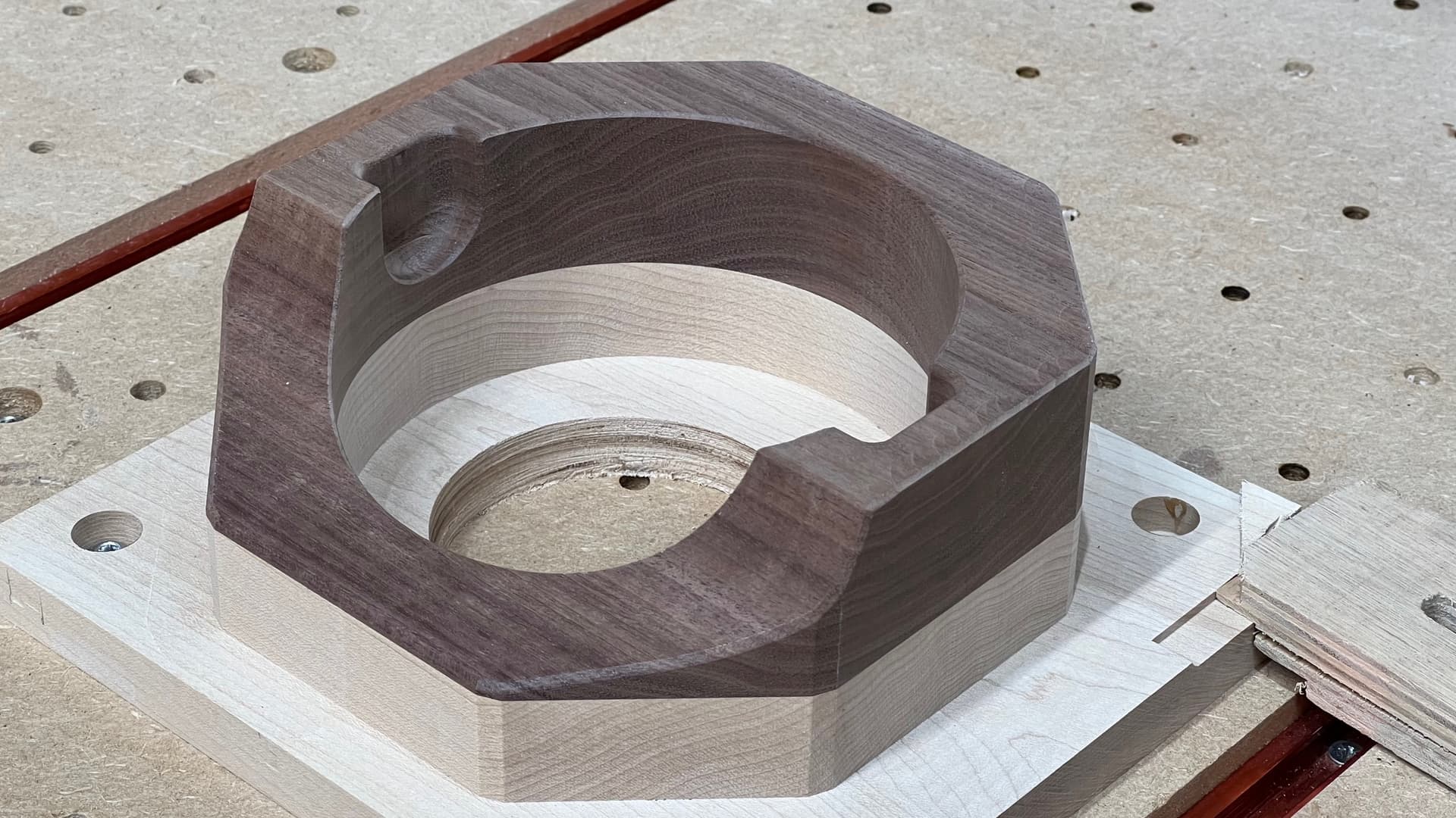
I use these two bits a fair amount for curved surface finishing
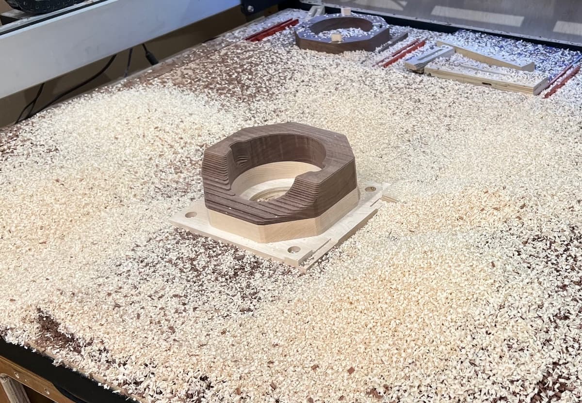
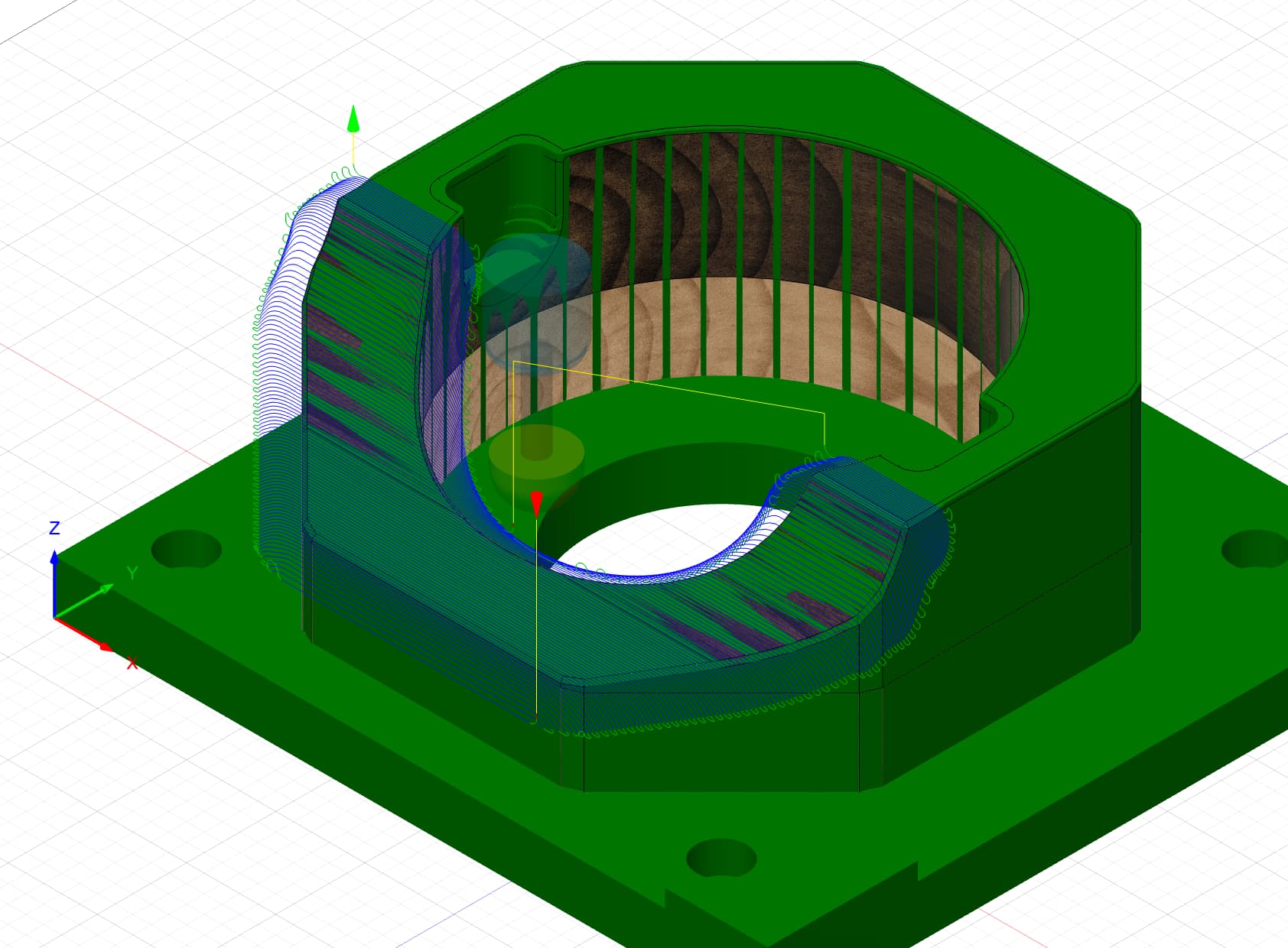
I tend to use the largest radius that will still reach into the features, in the case of the piece below, the 19.1mm for the large curves and the 10mm for the smaller pockets.
Those pics are all on the machine with no post-finishing work.
Finish on Pine will likely be a little rougher and I would likely run a larger stepover to reduce machining time, however in the case of this complex curve set in walnut I didn’t want to change the shape whilst sanding.
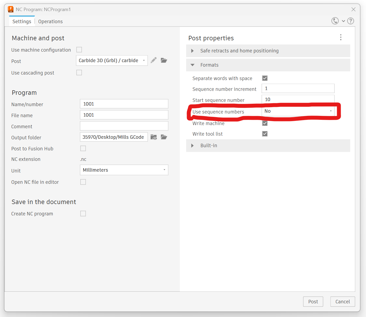
I’ve done an 8 hour 3D carve in aluminum and didn’t hit line number issues. It’s an easy fix. In the post processor, Set the “Use sequence numbers” option to “No”. That removes the numbers so that grbl ignores that and you don’t hit a max number.
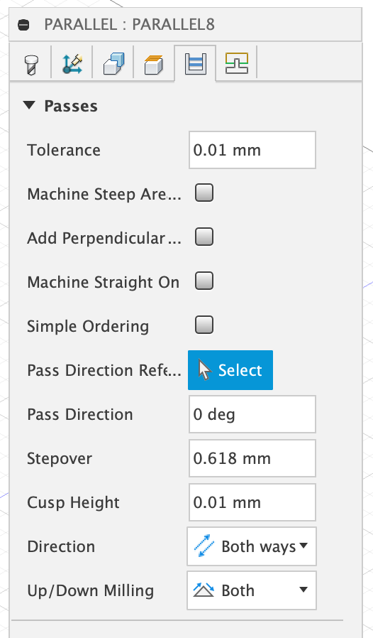
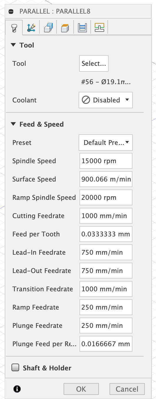
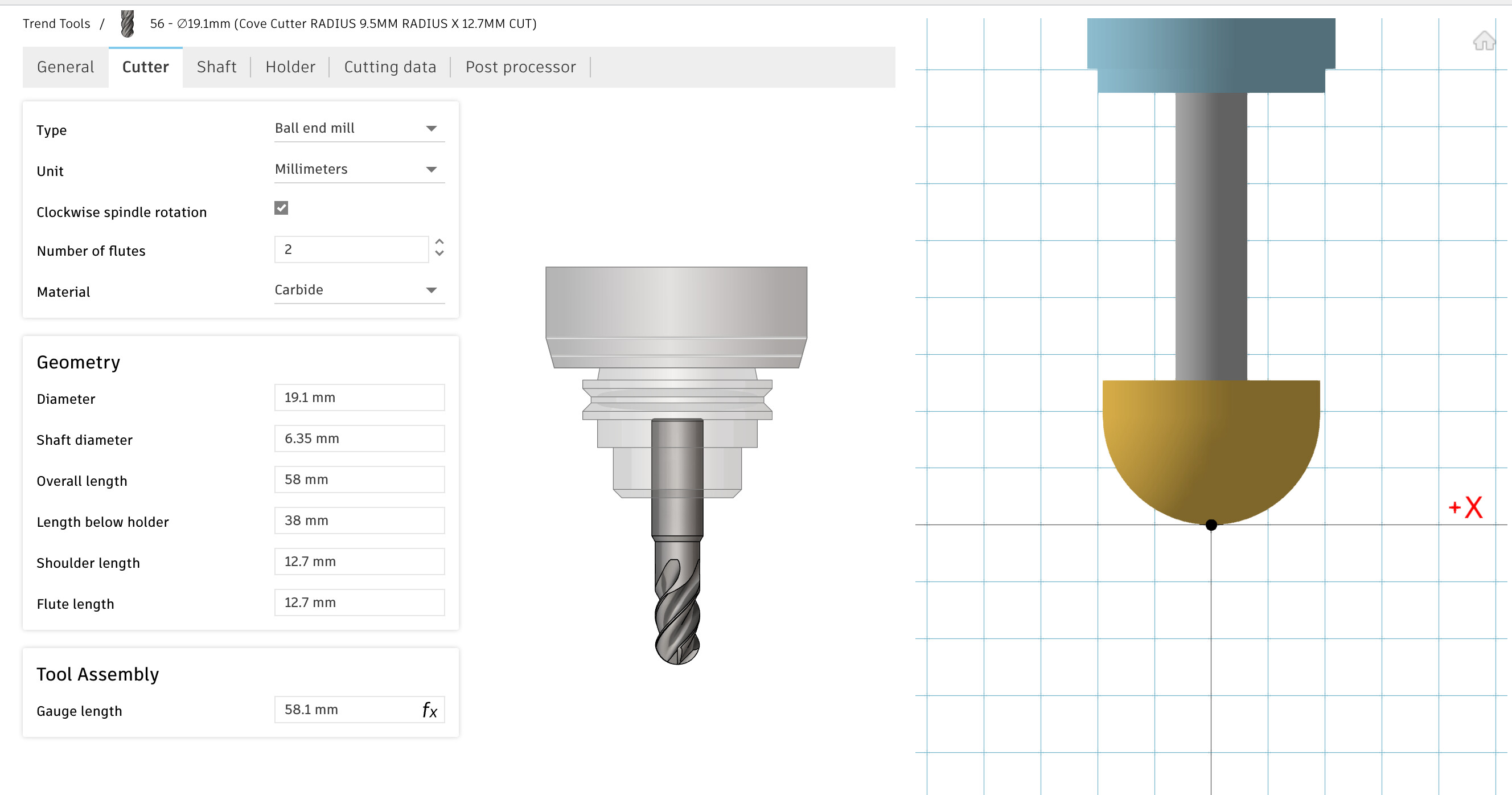
I don’t think the Trend bits are particularly special, they’re reasonable quality and predictable geometry but I’m sure there’s US vendors with equivalent bits. Once you’ve worked out how to set up the reduced shank ball end in Fusion it’s easy to set up more. (screenshot below just in case anyone else comes reading later)
A quick look at a certain US store suggests CMT, I’ve had good experience with their router bits and table saw blades
That’s a bullnose profile rather than a ball end mill when set up in Fusion, there’s lots of these with top bearings which I suspect you could just remove for use on the CNC
I’m still learning how to use the cusp height and similar settings to get the right balance between time on the machine and time spend hand sanding afterwards. On a piece this large I might break up the toolpaths into a mix of contour, spiral and parallel and set different stepover or stepdown based on the surface complexity. Or maybe let Fusion do the “steep and shallow” thing and see if that works. You can get a pretty good view of the leftover cusps in simulation and figure out what stepover or stepdown limits you need for each area, I frequently run several toolpaths on the one tool.
I am learning how well the simulation works. The tool marks in the wood are just like the simulation. Now if I could get by that GREEN default.
It is shiny so really clean surfaces are noticeable.
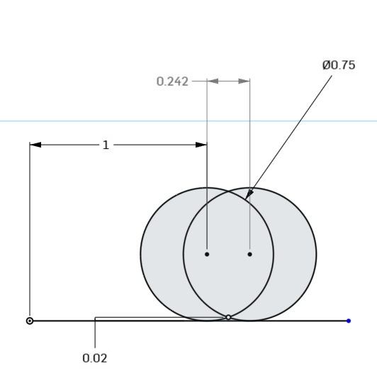
I bought two Whiteside round nose bits 1406 (3/4) and 1404 (1/2) with 1/4 shanks.
This will have no problems cleaning the pine.
I did not want a flat, not sure why, but that’s where I went
I am going to exercise the cusp height setting. I would seem logical if it controls the remaining ridge heights to sand. TBD
I don’t care too much about time until I get a good results.
The next piece is the nose. The front stock across the nose.
I use a DownTown Jenny to 3D Pocket first, 0.08 inch max stepdown. (2 mm) stock to leave.
I had done climb only last time, I am going to both next time, to reduce run time.
You can calculate either one from the other, the driving dimension is the one you enter in the CAM software. In NX, I can enter either one & it will calculate the other.
Yep, in Fusion I found you could enter a value in one and it would set the other.
What I had more trouble working out was whether the cusp height was calculated on the angle of the surface being machined, and if so, was a single stepover or stepdown set for the whole toolpath to minimise the worst cusp or does the calculation assume something else?
I like the cusp height option because that is effectively want I am looking for in a finish cut.
I have done carves where the features snap off if the step down is too great, It creates peaks that break off taking the “base” model with it. So I will watch the step down.
I don’t have Fusion, but if the top view of the toolpath is straight parallel lace/zig-zag/raster lines, then the scallop is calculated on a flat plane. If it’s following the contour, the lines will morph closer together on the steeper surfaces. If you have steeper contours, either set the direction so it’s going up & down the hill rather than across it, or reduce the stepover to accommodate it.