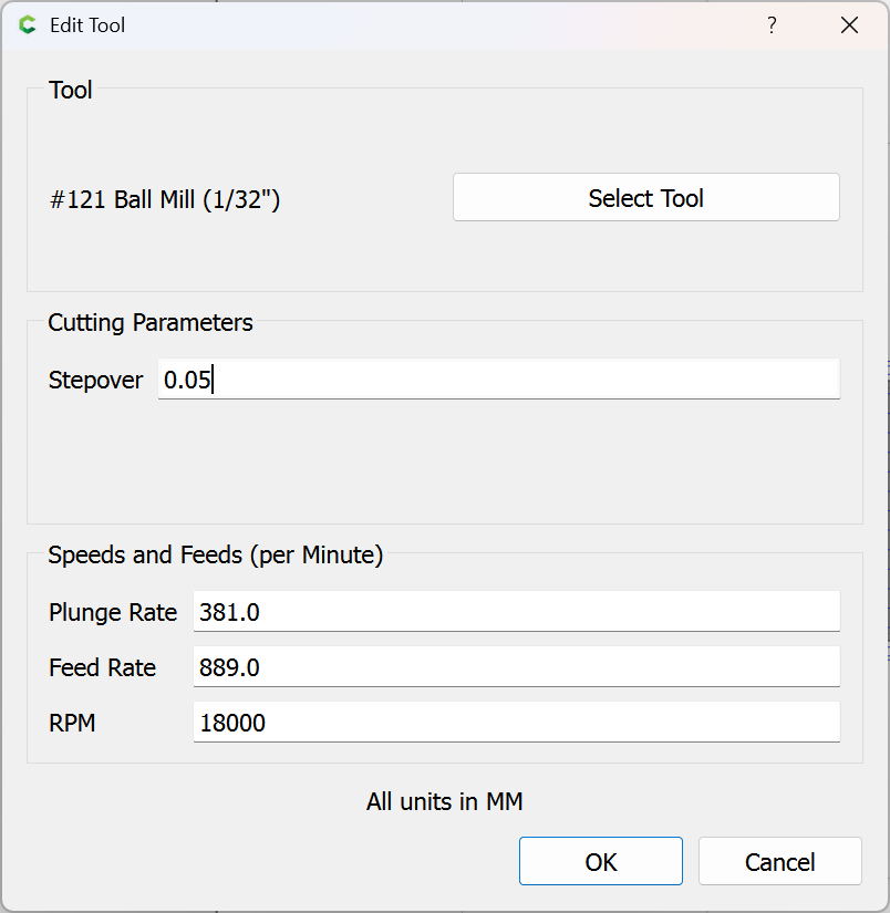
Hi there I just got the carbide create pro and have been doing test cuts on some wood with the 3d rough pass. I’m seeing odd gantry movement on any round contours, it’s sort of stuttering and isn’t smooth at all.
So I checked my bed alignment and did some simple circles in 2d contour and the gantry moves smoothly as it should on various tight and wide curve contours.
I’ve seen other people post this same issue on earlier versions of carbide create and they seemed to solve it by going to previous versions. Those posts are quite old now though and there are many updates since then.
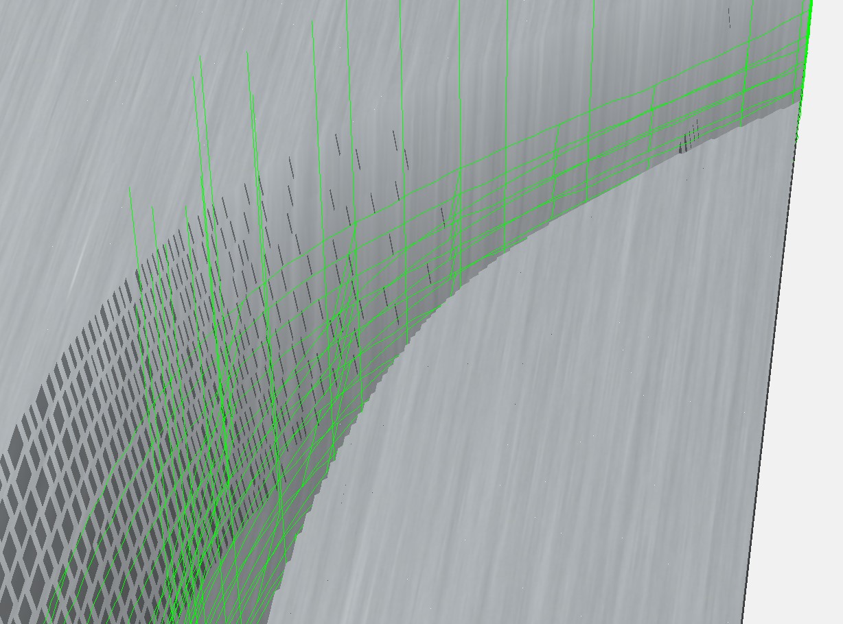
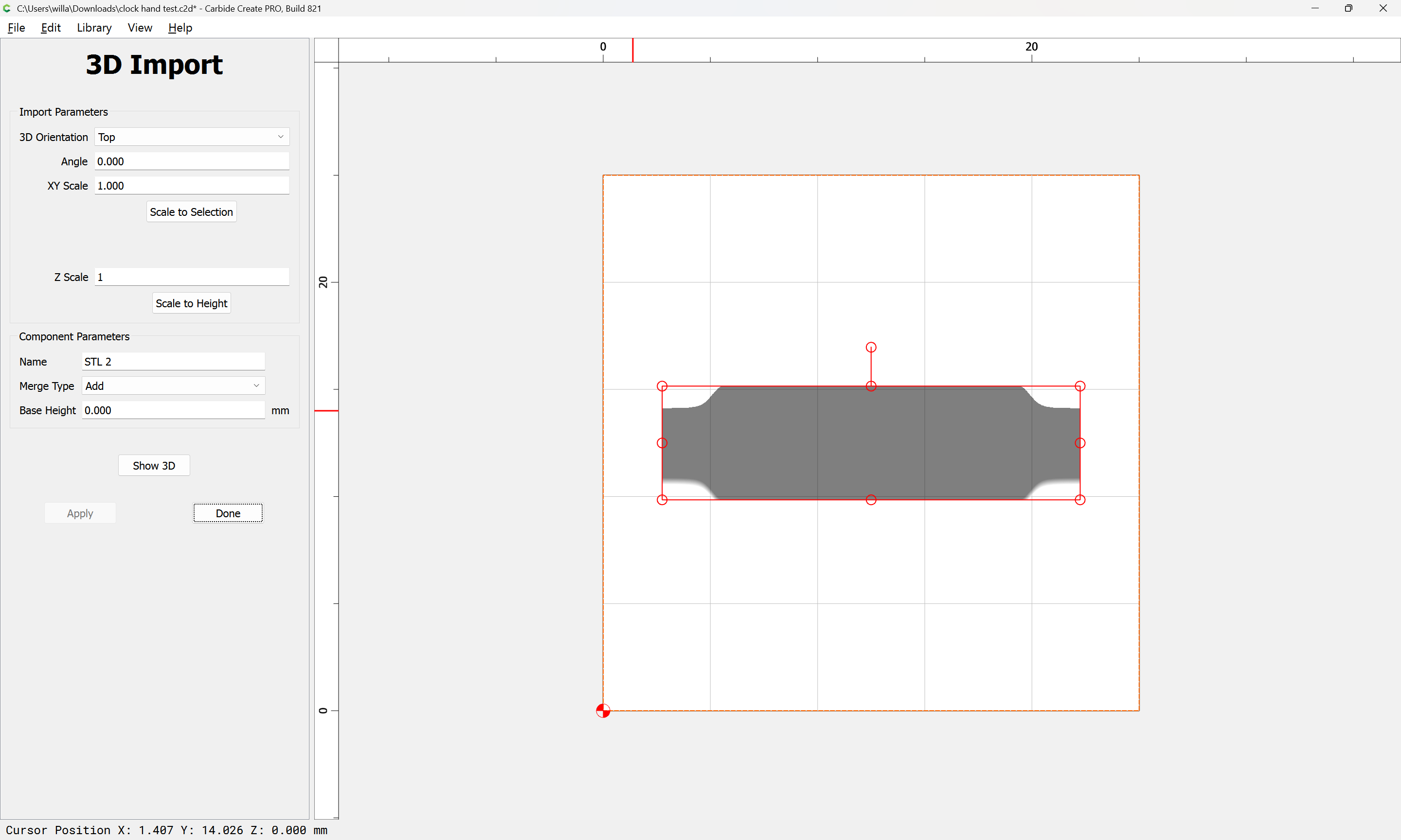
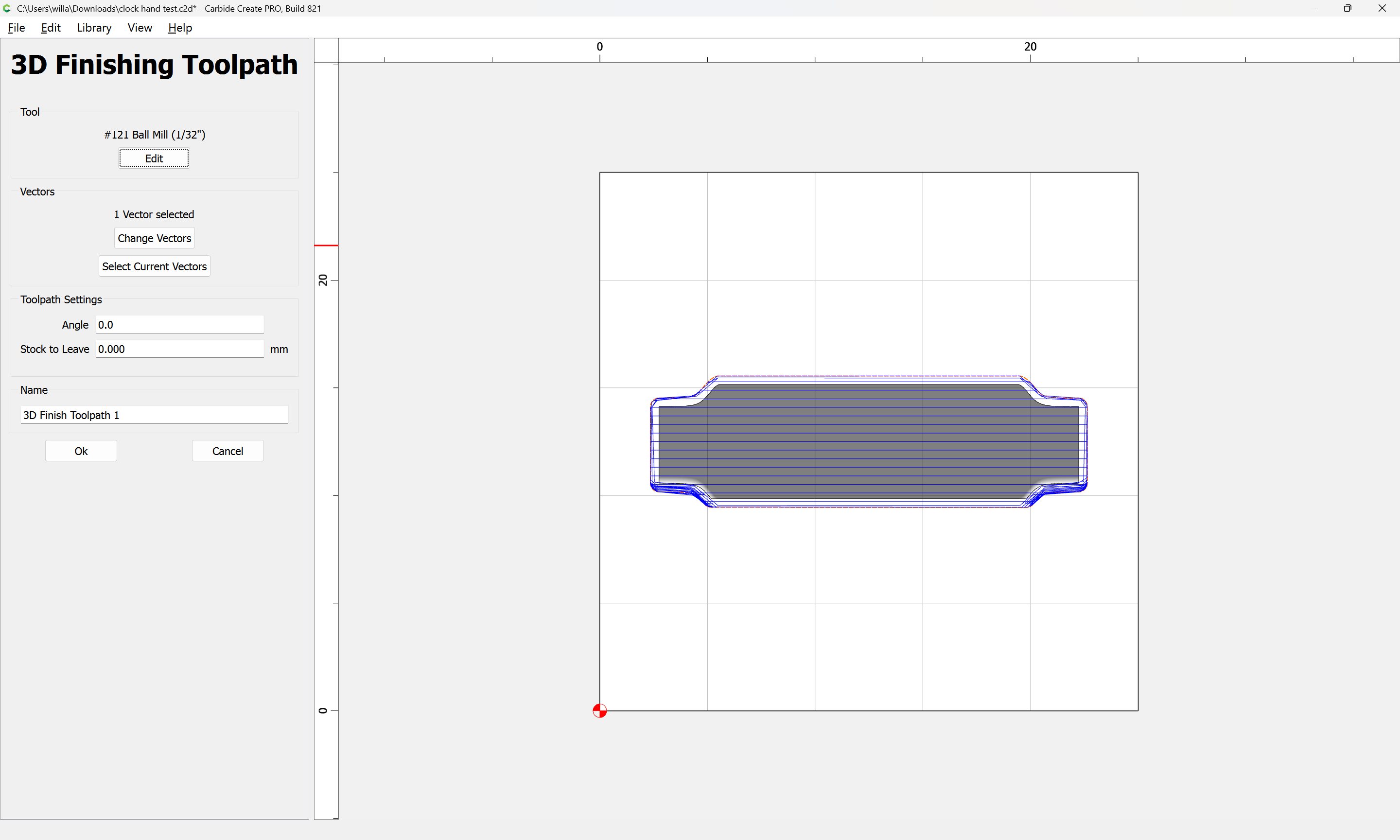
The toolpaths look a little bit bumpy so I am wondering if the STL formatting might be causing this in some way.
The finish is okay and you can’t really see the result of the stuttering unless you look closely but it does require more sanding to get it smooth than I’d like. Any help would be greatly appreciated!
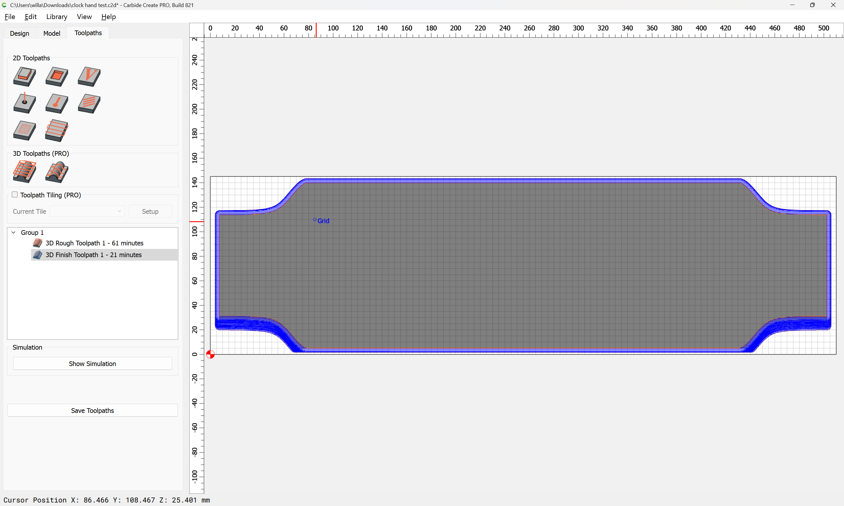
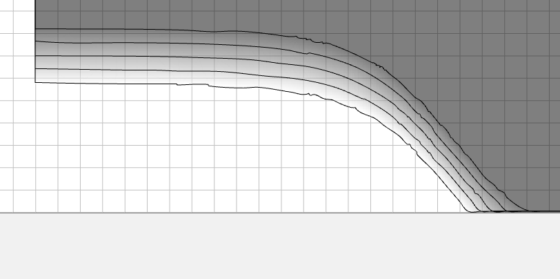
Here’s a photo of the tool paths I simplified so you can see the steps easier
Carbide Create converts things to polylines to make the math simpler — but it should be done with line lengths short enough to result in an accurate representation.
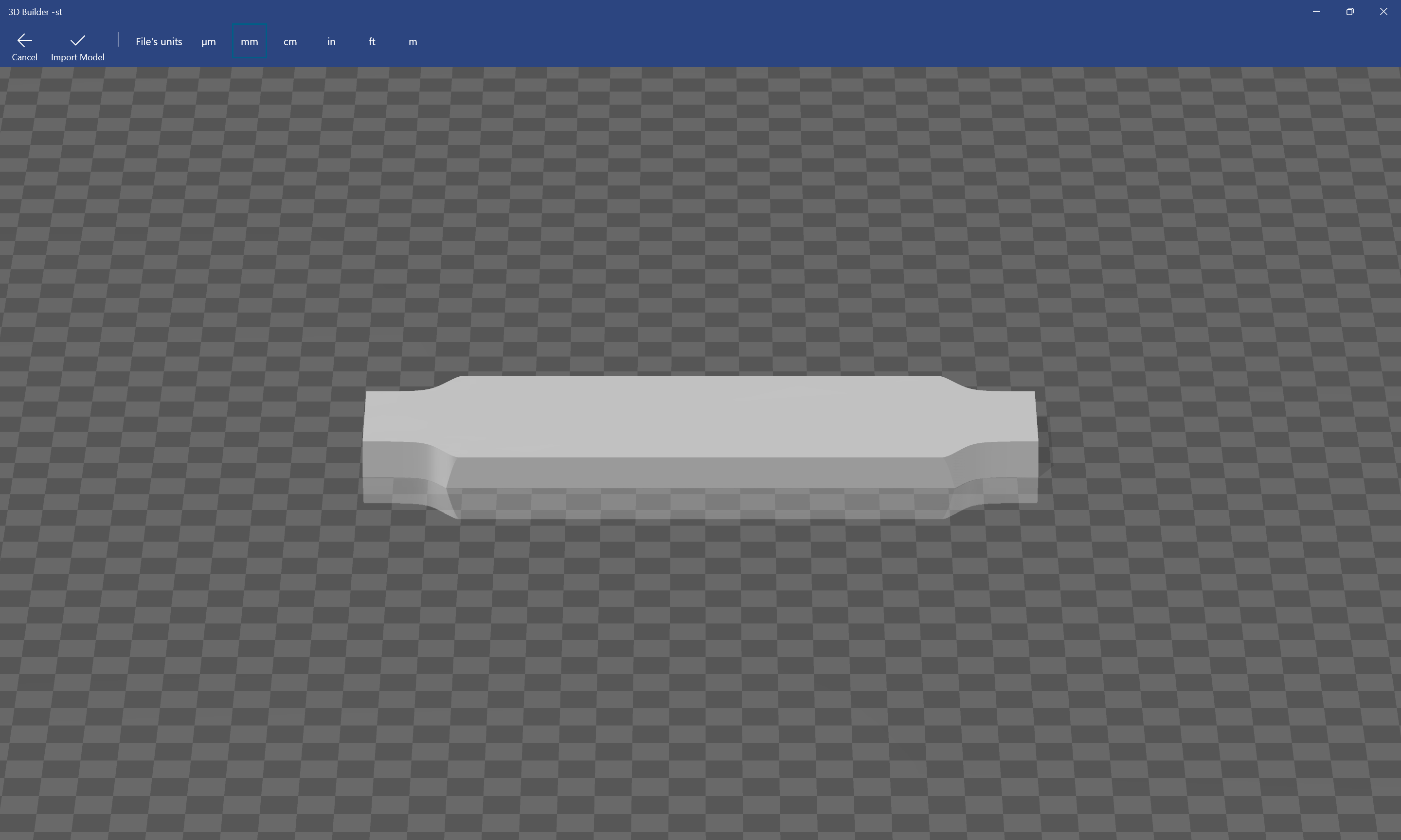
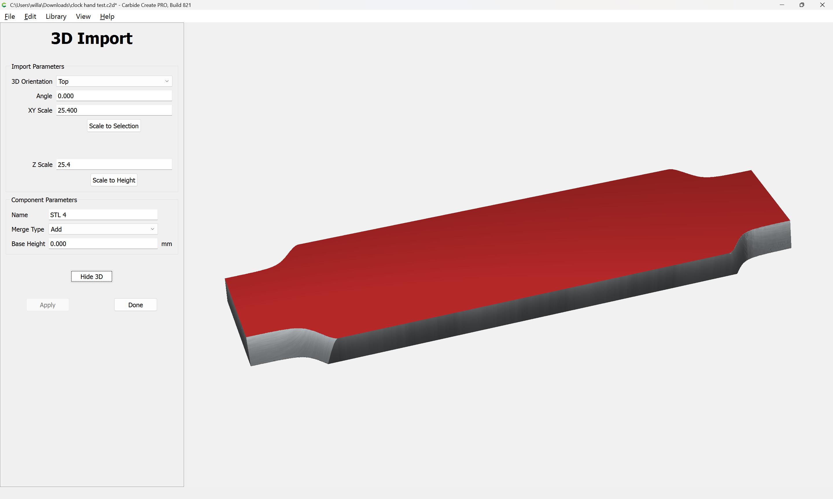
What does your source STL look like in a third-party 3D viewer?
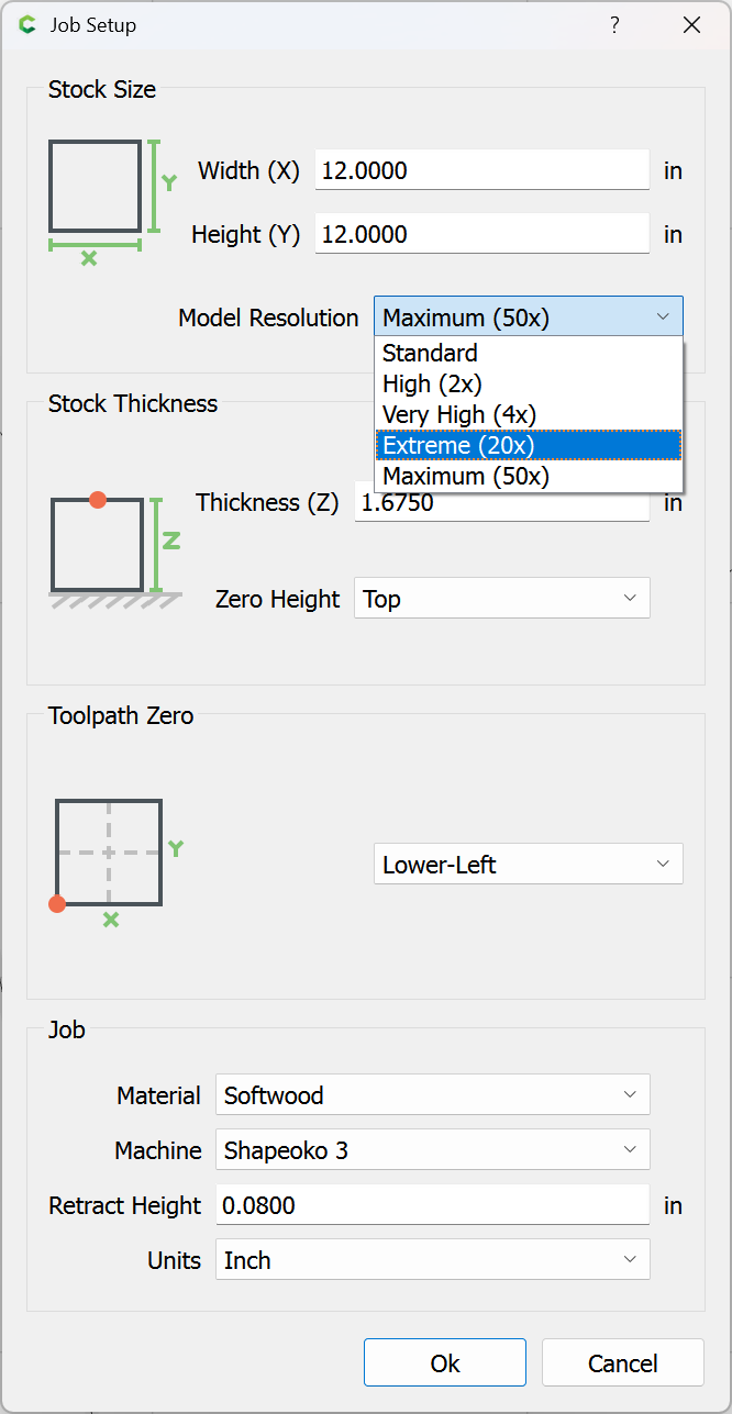
I just realized I have an older version of carbide create on this computer than the one connected to the machine (V7). I’ve downloaded 8 and will try again. I did notice that I don’t have the same model resolutions in the dropdown as you do, it only shows standard, high and very high in the latest version I just installed. I’m using Rhino3d for exporting the STL.
Here is the same file in v8 and the toolpaths look way worse with zigzags. (in any resolution). V8 test.c2d (456 KB)
I just ran this program to see how the machine would react and it’s really moving around erratically now on the round contours. Way worse than the carbide create v7 stuttering issues I had.
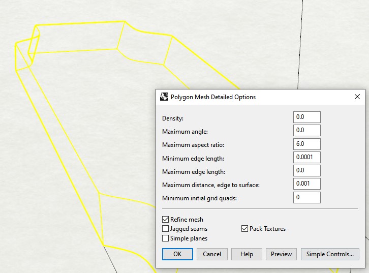
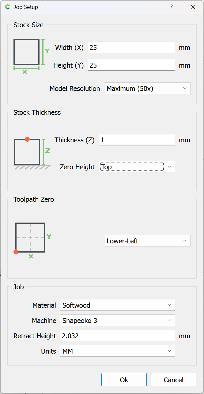
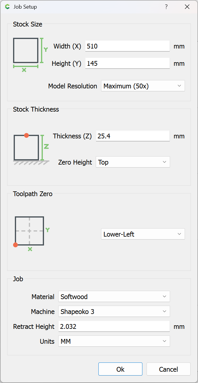
Here are my settings for exporting the STL if that helps
I have everything set to inches I’m not sure if that will change what you did here? I played around with the export settings from Rhino3d by changing the maximum edge length to .1 (anything less and it wouldn’t compile the toothpath in ccp) The mesh preview showed a lot more contours in the export and I think that helped as the contour toolpath motion in the machine is much smoother now (not perfect but way better).
I only have the trial of carbide create pro so I will see if Meshcam works better. I really appreciate you taking the time to help troubleshoot this.
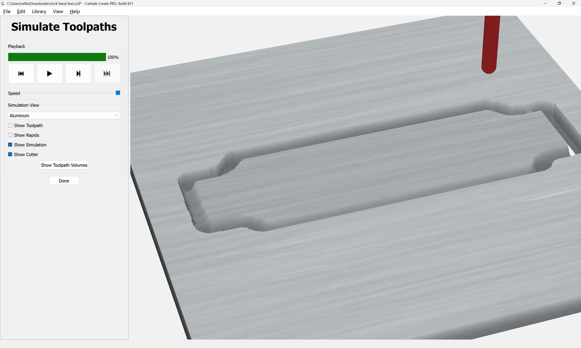
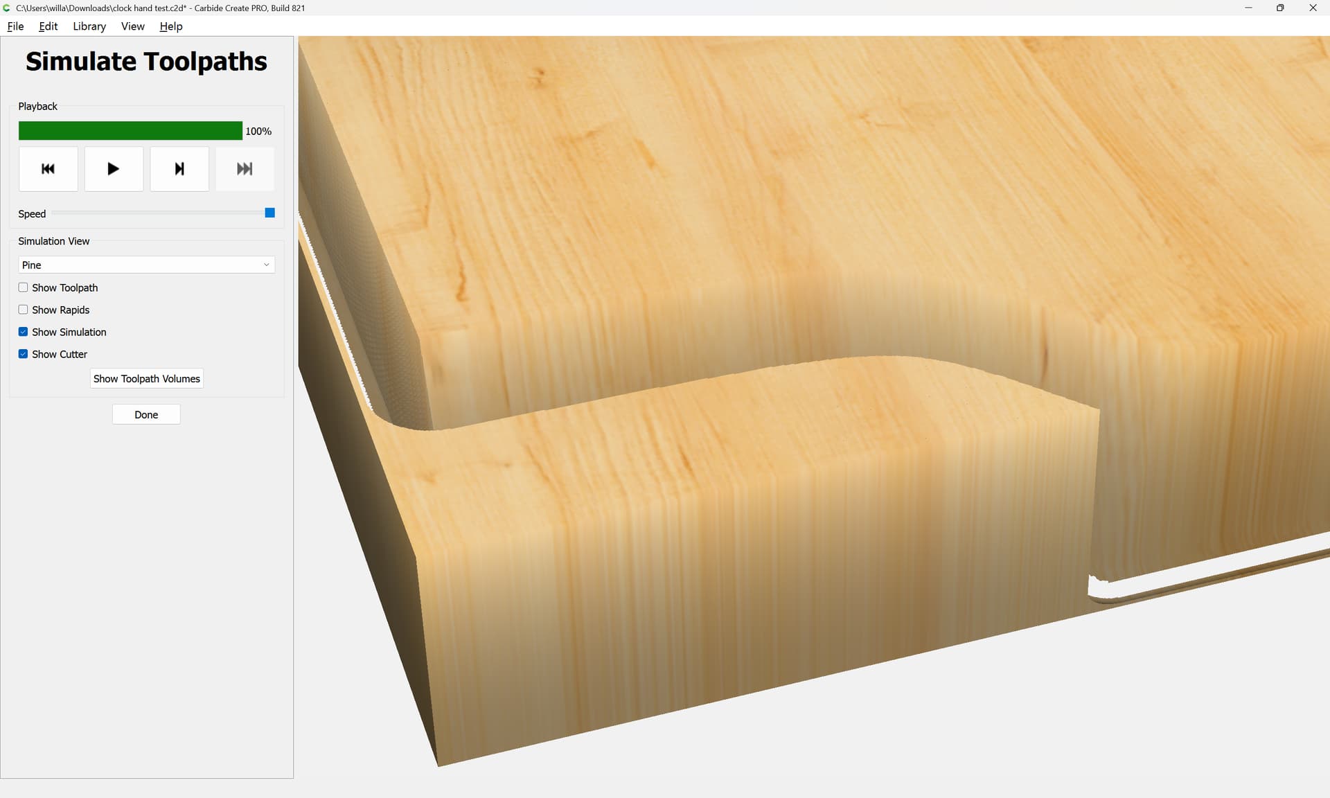
It appears that in the st_v8.c2d file you sent the simulation is not cutting in 3D. The path is straight down and not cutting the angles on the corners. It looks like the angle is there in the photo you uploaded though so I’m not sure why it changed on my end (in both rough and finishing pass it’s straight down).
I tried meshcam and the toolpath is moving exactly as it should when tested on the machine, smoothly with no odd jittering movement.
MeshCam uses G2/G3 circular interpolation (i.e. true arc movement) on constant-Z moves (i.e. in a level plane). Carbide Create approximates arcs with many small linear segments. On large-radius arcs, there isn’t much difference, but on smaller-radius arcs, even my Nomad judders. This is especially evident when “rolling” a cutter around a square outside corner.
That’s interesting because I would assume that the 3D toolpath isn’t technically different from the 2D toolpath in carbide create in that they are both moving in the same motion. I made a version of the same piece which cut straight down using 2d contour and there was no jittering movement at all.
What you’re saying about carbide create and the small linear segments in 3d roughing makes sense, which I think would be fine if the toolpaths weren’t so wobbly on top of that.
I’m sorry, @ingotvein, I might have misunderstood your problem. It sounds like more than the CC curve interpolation. I’ve never used Rhino3D (my main experience is with SolidWorks), but looking at your STL export screenshot way above I see the setting Maximum distance, edge to surface which is set to 0.001. Just as a shot in the dark, that is R3D fitting tangents to the modeled surface, which will ultimately determine the mesh density as the local curvature changes. You might try tightening that number to 0.0001 and see how much of a difference it makes on your part (or even a test case, like an ovoid or egg shape). That is independent of the Carbide Create input, where Will showed the corresponding setting CC uses , I’m guessing when parsing an STL.
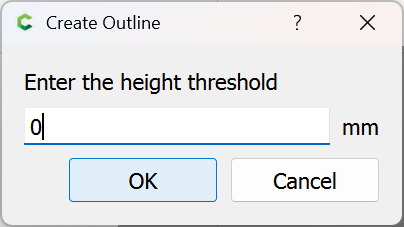
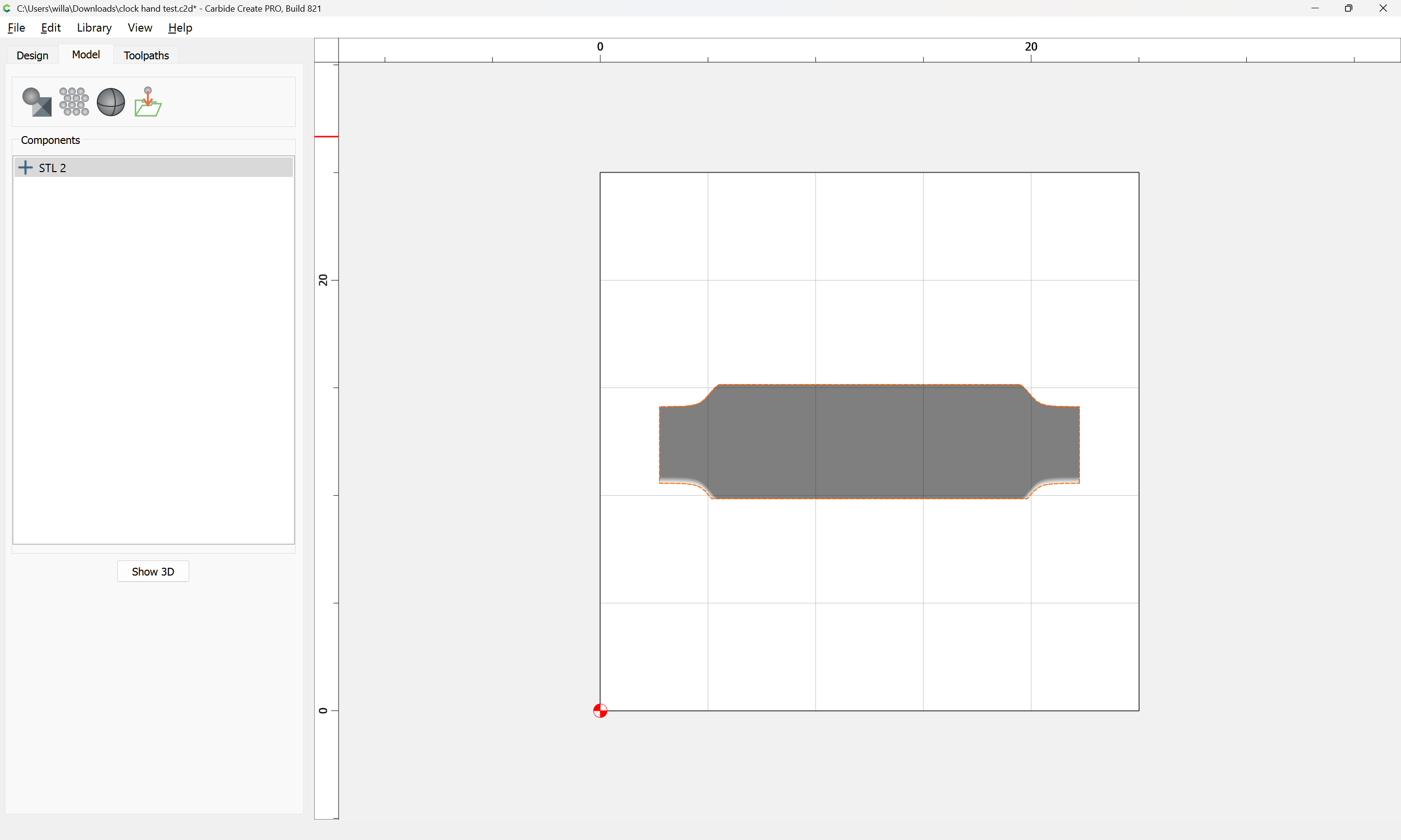
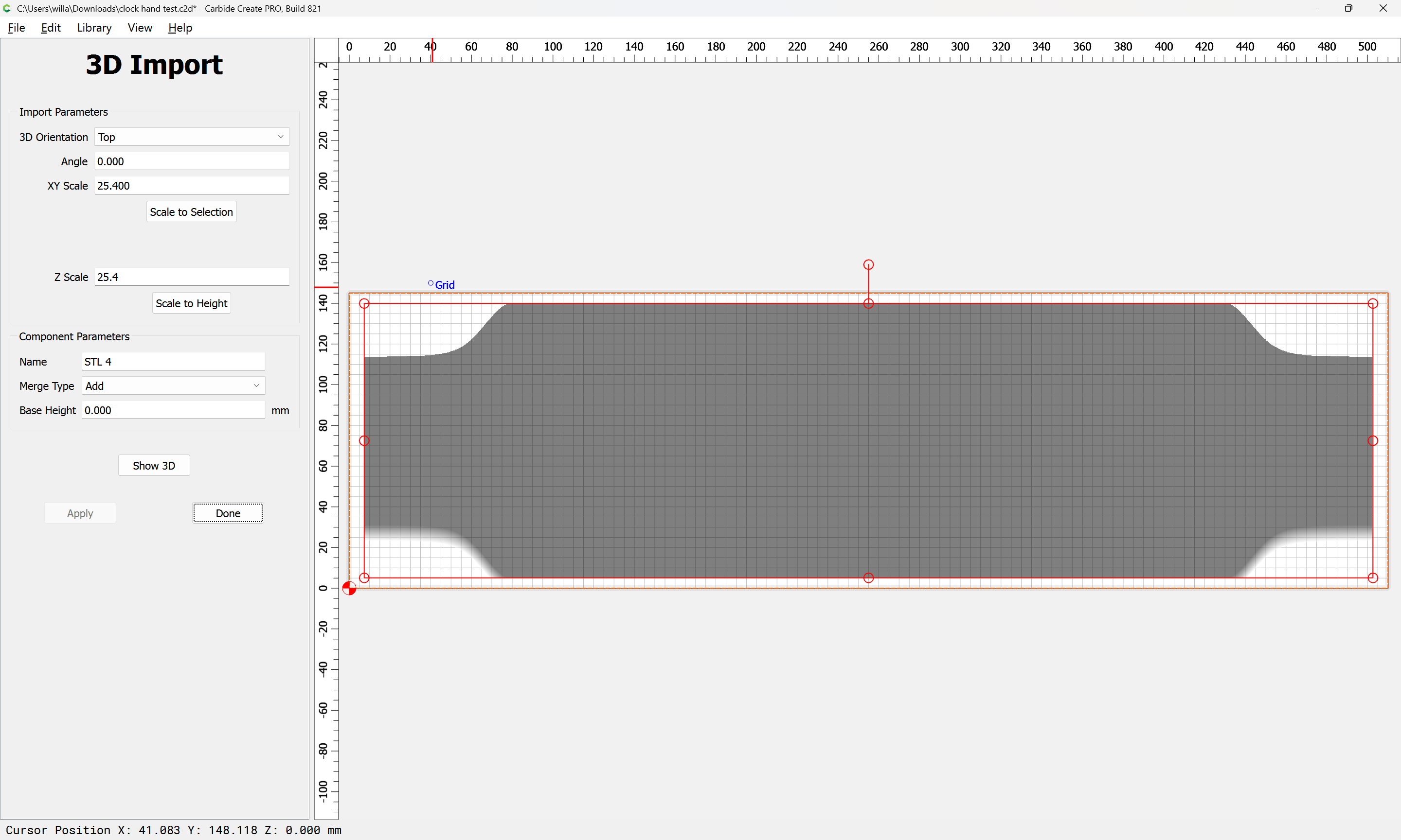
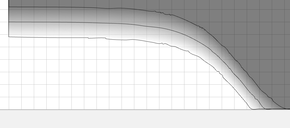
When CC imports a STL, it converts it to a 3D height map. Similar to a 2D bitmap, but with a 3rd dimension. You can see the edge trace after the conversion is not very smooth, and if you do another edge trace at 0.5" or 1.0", you’ll see it’s not that great either. It’s just the nature of the 3D format.
I will give that a shot, I definitely had better luck by reducing the edge length but I will try the maximum distance setting next. So far I’ve been running tests with meshcam and it’s got a lot of functionality like being able to set zones to machine or not machine which is really useful for this particular part, as it has to be flipped to get the same shape on the opposing side.
I think what you said about it being similar to a height map kind of makes sense in the way it’s interpolating the object and outputting rough looking toolpaths. As if it’s trying to create toolpaths from a low res object. I’m likely not going to keep using CC but I am going to keep playing around to see if there is a solution anyway.
You are correct there, sir! I have extensive experience with MeshCAM but that goes back 8 years or so, and I’m just about to get back into it. It really is an excellent program. In earlier days with low-resolution STL’s, MeshCAM’s toolpaths would faithfully follow the individual facets. I’m sure they still would, but STL generation has gotten a whole lot better.
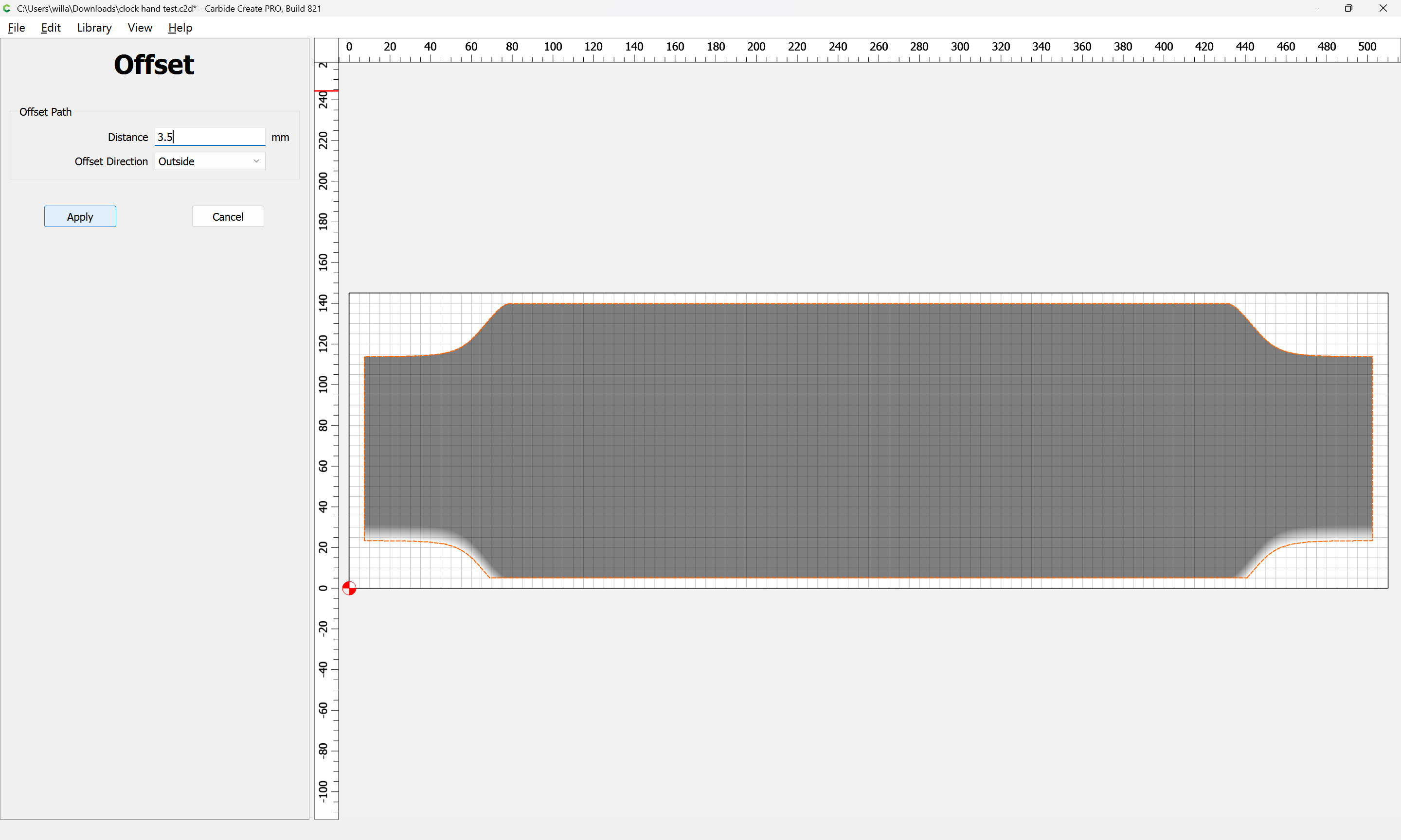
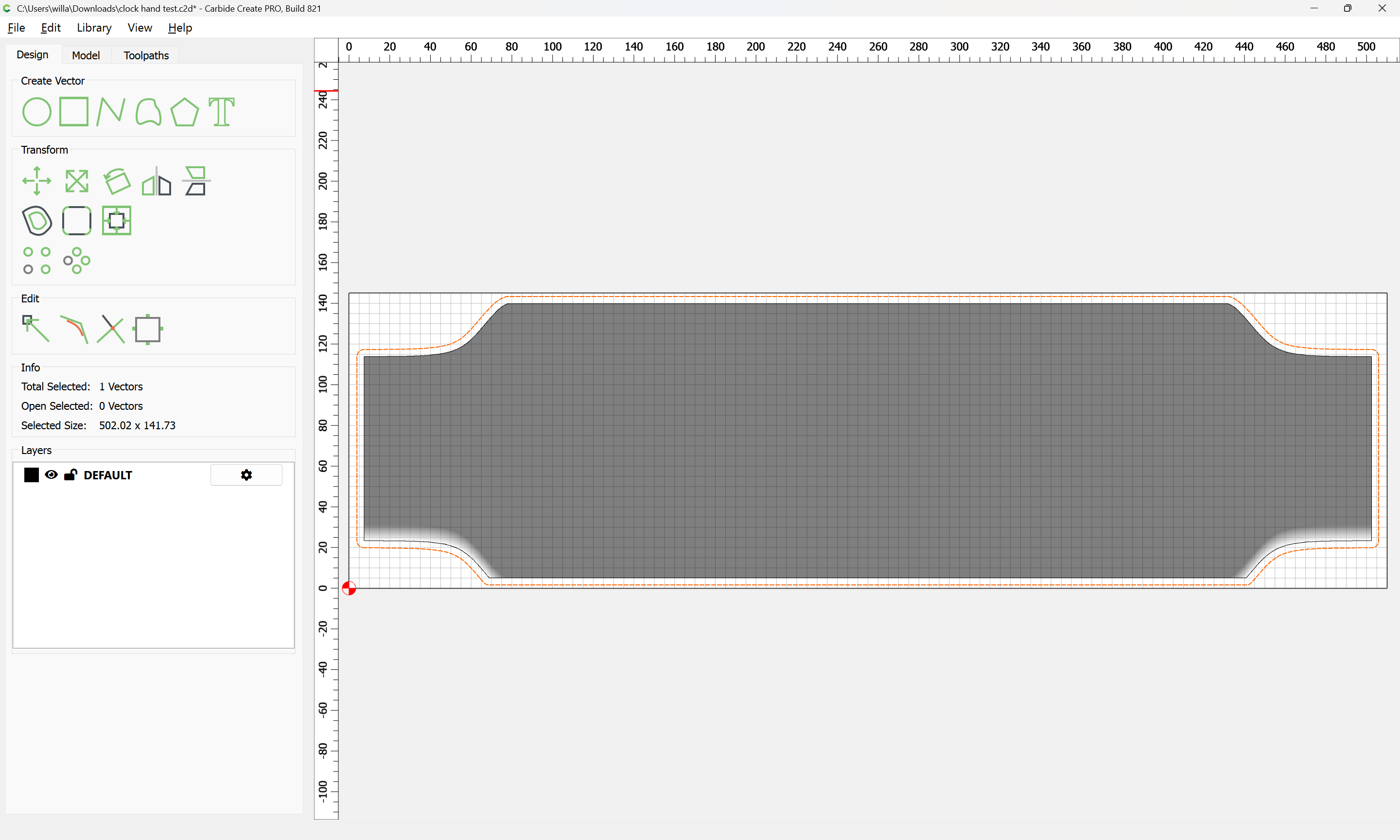
You could replicate the algorithm that other CAM software uses for Z-level machining by creating Z section lines, offsetting & contour path each section at a different depth.
Like this, but with the sections cut through the original solid model