Seems like there are some artifacts in my design, which I can’t figure out. It’s extremely simple, created 100% in carbide create. What is going on here?
Also, why can I not edit model heights again after I create them? Is that going to be fixed in a future version?
Sometimes you have to overlap the 3D components a bit to get the desired result. But from looking at your file, it looks like it would help to turn the Model Resolution to Very High in the Job Setup settings.
After changing the modeling to Very High, the 3D roughing seemed to calculate out completely. I would also adjust the Stock to Leave setting in the 3D Roughing Toolpath to 0.100" .
As Will referenced, the v8 Beta allows more flexability when it comes to the 3D modeling components & editing them after the initial setup.
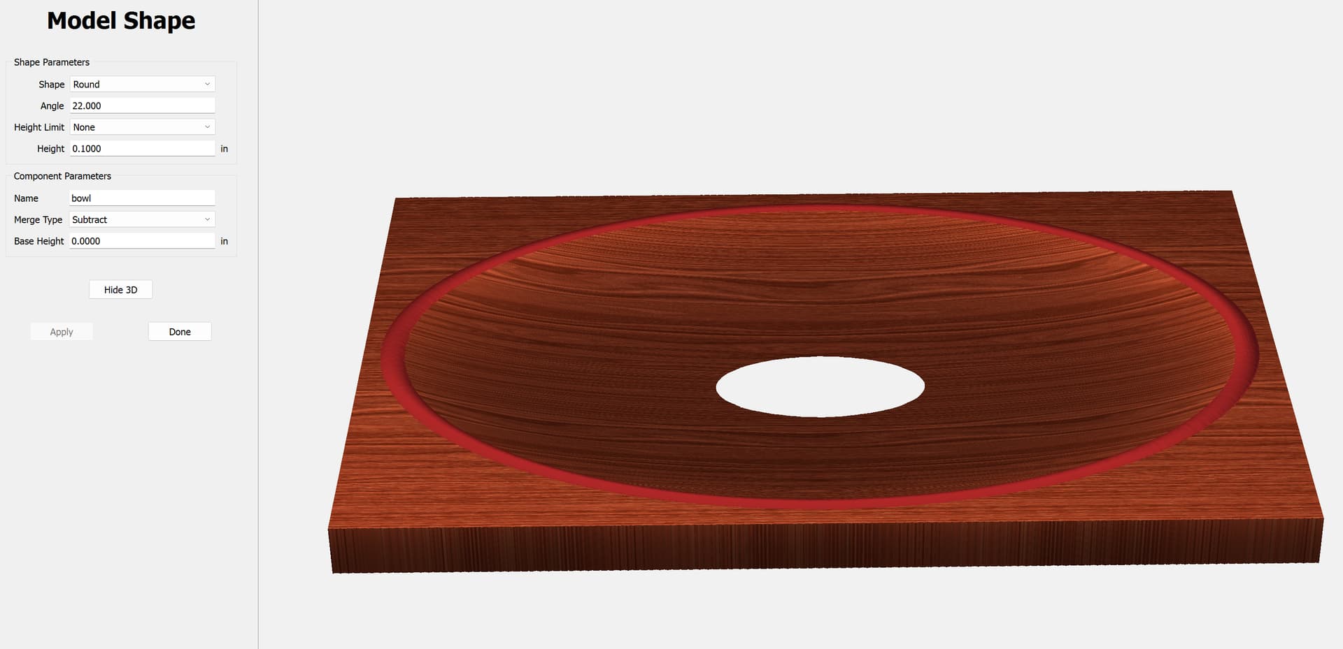
Not sure what you mean by ‘referencing height’. The Model Shape pane allows you to define a shape with the Height Limit & Height parameters - if Height Limit is set to None then the Height parameter usually doesn’t apply. A quick modeling test shows me that the Subtract function limits the component by the set amount.
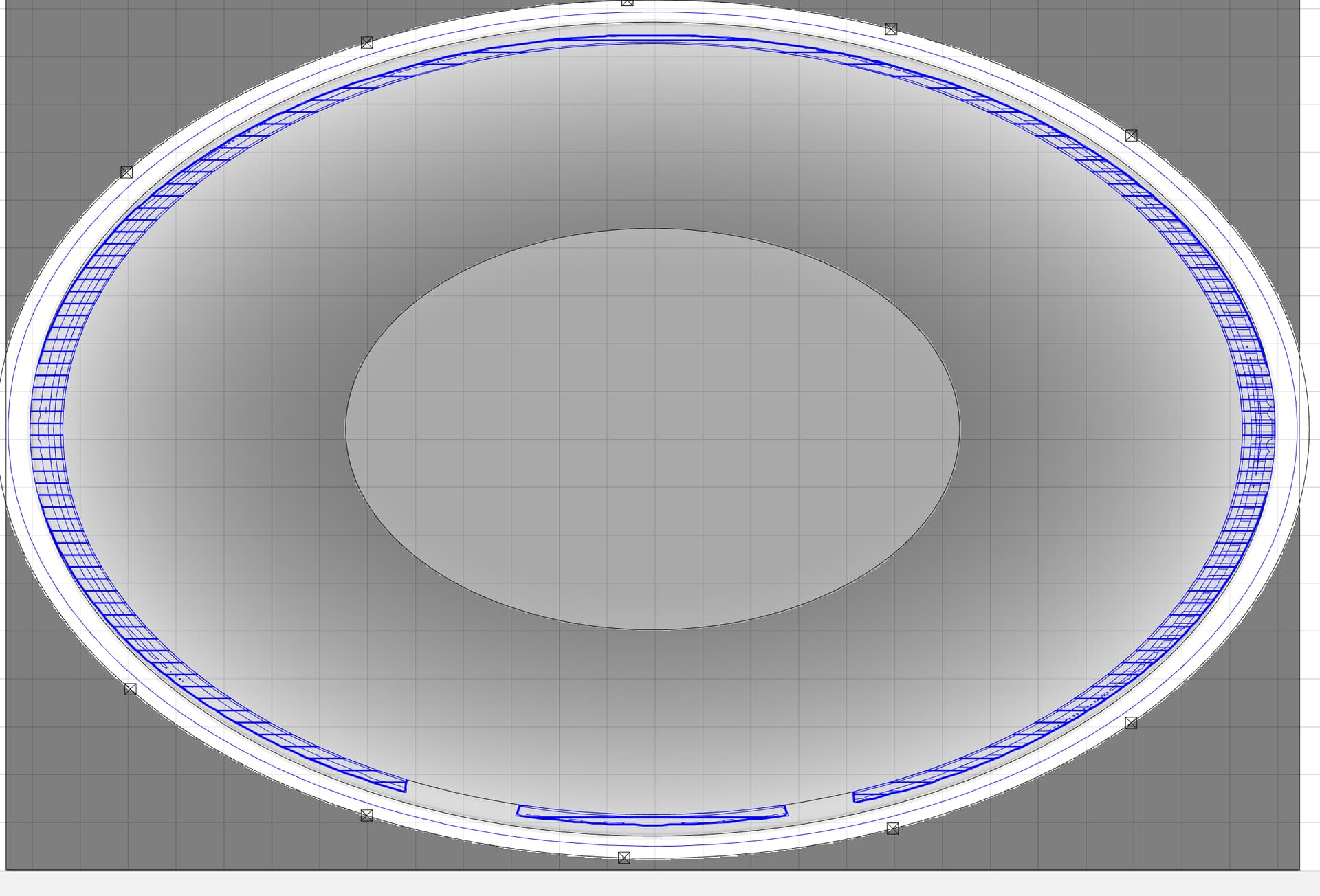
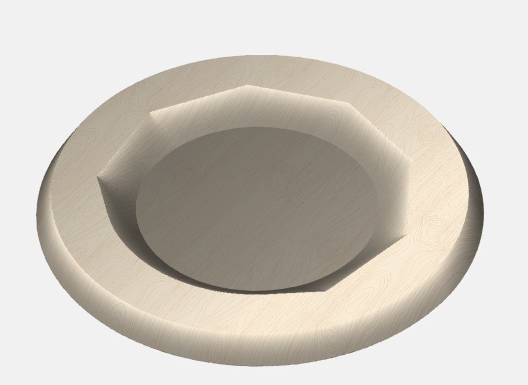
However, in doing my quick test, I did discover a quirk in the modeling. I made a base circle with a 9-sided polygon subtracted in it. The 2D view shows what you expect. But upon generating the 3D model, the polygon loses a few sides.
Tested polygon shapes below 9-sided & they all seemed to render as expected with all sides. But above 8-sided, it seems to reach a limit & create a curve in place of the sides it can’t handle.
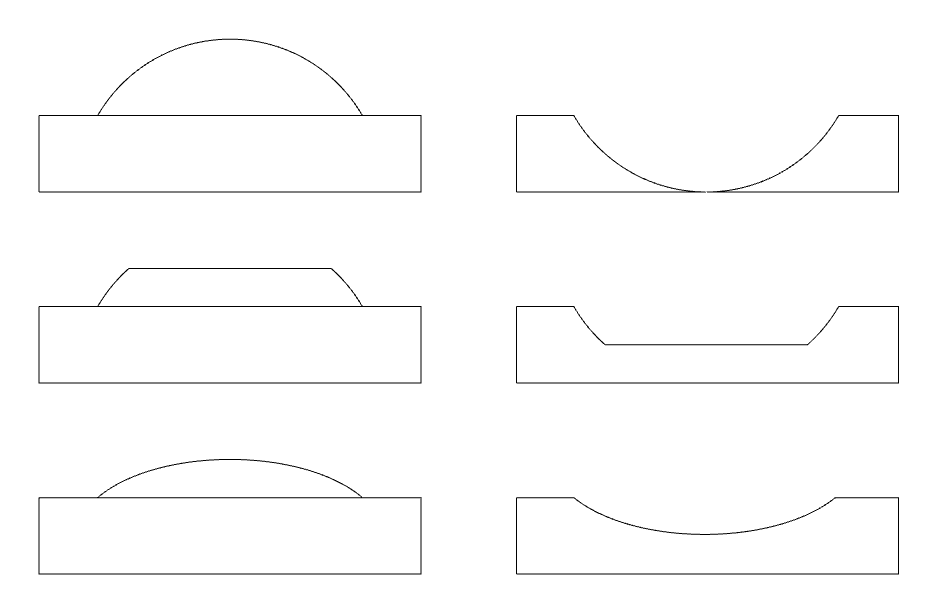
If I define an angled or round component, let’s say with a 45° angle, with no height limit, I will get a shape defined only by the angle. With a 45° angle I’m getting a quarter of a circle.
Top image is no height limit, add on the left, subtract on the right.
If I limit the height to something smaller, it chops it off at that height.
If I scale the height, it scales the whole feature down to that height.
Thanks, all of this makes sense. I must have been flailing all around the past few days learning about this software, and got myself confused. Now if I choose a height, and subtract, it works as expected.
I could have swore that the height was not working with a subtract, and I had to use the ‘base height’ instead, and the height parameter wasn’t being used. I can’t seem to duplicate that now though, so no worries.
V8 is exactly the feature I wanted for modeling! And I never noticed the modeling level being able to be set to a higher value in the project setup. No more screenshots for me!
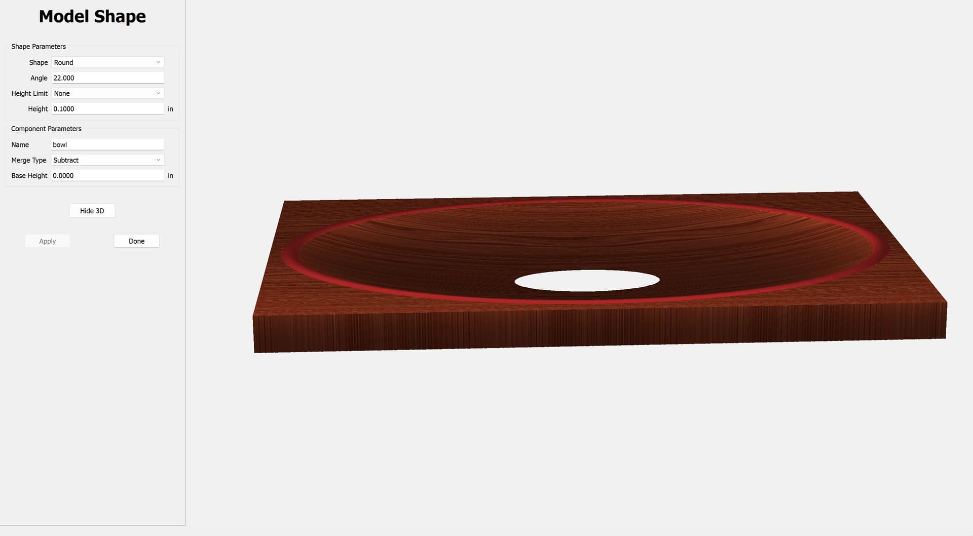
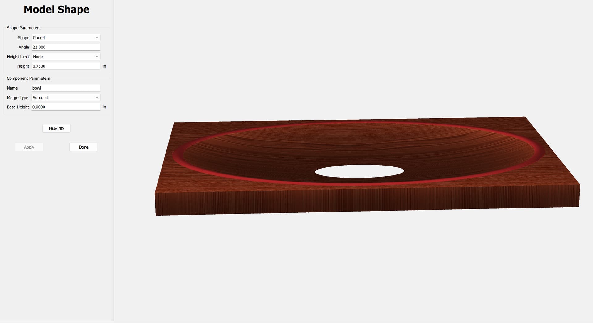
I have attached 3 files - with the height set at .10, .50 and .75 at a .75 inch thick piece of stock. It doesn’t matter what its set to, it always has the subtraction the exact same size.
also, ‘save as’ does not work if you are on an existing model and haven’t click ‘done’
unfortunately i cannot save the files here, as they are over 4mb. got a backup when that happens?
edit: perhaps im misunderstanding the angles here, but I would expect no matter what angle i enter, it should stop once it reaches the height i specified
edit2: as it stands, it seems the only legitimate way to curve my bowl on the top, is to reduce the angle until it no longer gets to the bottom of the stock. I would highly prefer to be able to angle sharply (25 degrees) down to the center - at the height i tell it - and then it stop.
It is up to the user to keep the parameters so as to create dimensions which will fit within the stock — it is not the place of the program to do other than what the user requests of it.