I make wooden toys and thus cut lots of small pieces out of large panels of stock. Some of the patterns extend past the working length of the SO3, ex. 32” long panel (I cut a sheet of plywood into 9 pieces 32” long X 16” wide). The rubber band rifle I’m currently building has a length of about 28”. I need to cut the outline of the pattern in 2 cuts and the 2 cuts have to start at the middle of the pattern and extend towards one end and then continue from the middle and extend towards the other end, and they have to match up at the middle. This is how I do that, as requested by another member.
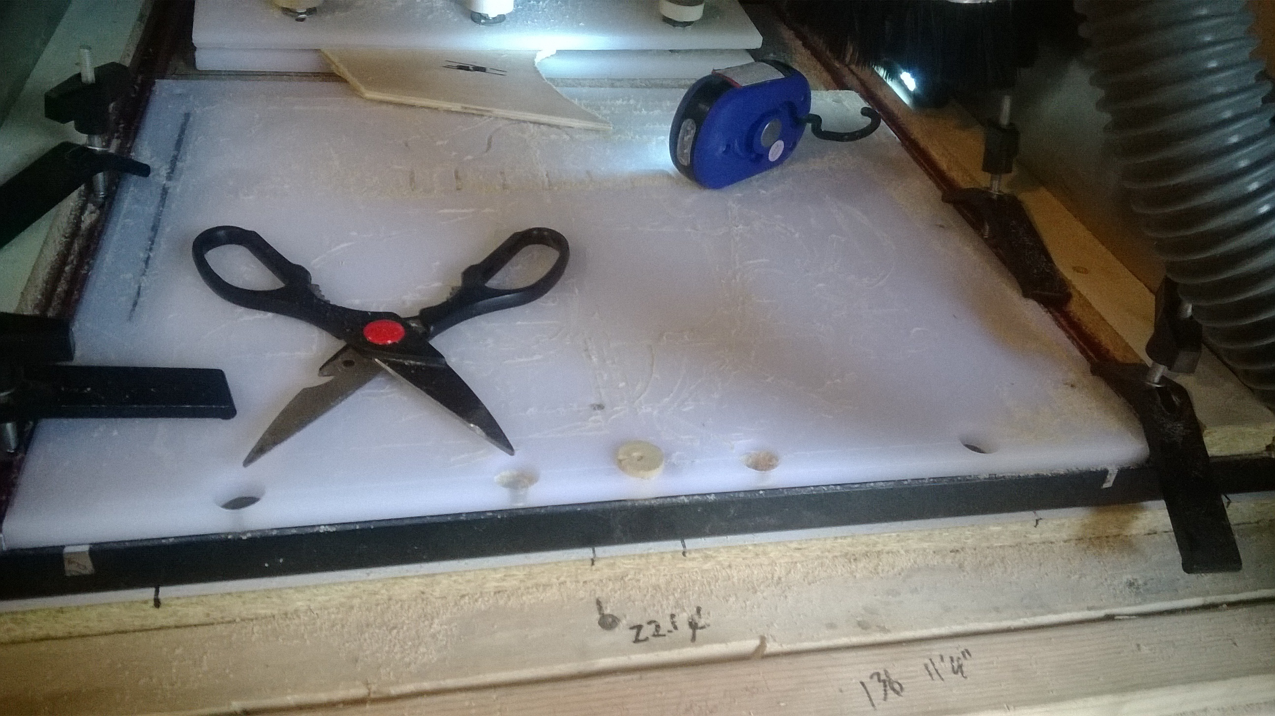
The first picture shows my SO3 setup (drawn in sketchup without the router for clarity and because my photography sucks). I have 3 removable pegs in the waste board. The holes were cut by the SO3 (so they are centered and in alignment with each other).

I take a project panel and diagonally find the center of it and forstner drill a matching sized hole in the center of the panel. This hole will center the panel onto the center peg on my SO3. Only half of the panel will be on top of the waste board but the SO3 can only cut on that half so I don’t worry about the unsupported half sticking out one end of the SO3.
The next picture shows my Rubber Band Rifle toy I am making. NOTE: Please do not copy this picture to use for your designs, it is my own drawing from scratch and I am trying to make money selling the toys. I simply trust your intentions as this tutorial is only intended for members of the Carbide3d Community Forum.
Anyways, the picture shows the full size drawing of the rifle pattern centered on a 32” x 16” piece of plywood. The greyed edges are the edges of the panel and the drawing is dimensioned smaller.
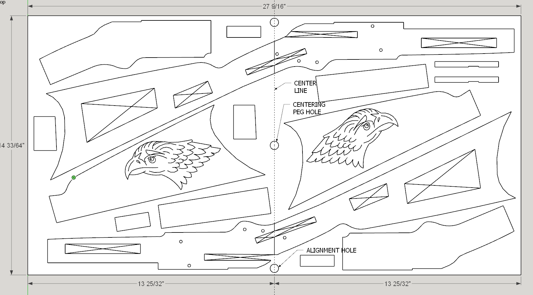
There is a dotted center line dividing the pattern in half, note the center peg hole that will be hand drilled prior to clamping onto the SO3. The alignment holes on each side will be cut by the SO3 (I make many of these so for the first one of this project panel I cut the side alignment holes with the SO3 deep into the waste board and the following panels the alignment holes are only cut thru the panel itself.) This aligns the side holes with the center hole. When I “zero” my SO3, I zero X and Y on the center of the center peg and zero Z on the surface.
The big problem is how to continue the pattern cuts after rotating the panel on the center peg hole and match the cuts in the 1st half.
Note in the rifle pattern a vertical line (on the center line) that divides the pattern into 2 parts. This is important and will be shown in the next picture.
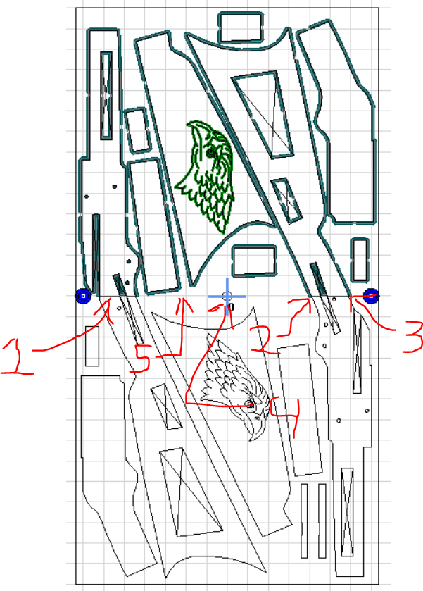
Note 1 is that line. It does not divide the cutting of the part but assigns a start point and end point which you can start from with the second half of the panel. In Estlcam, there is an “engrave” command that assigns a tool path to single lines which do not require being “closed”. Using that command, I start at the end of that line (note 2) and follow dot to dot around the pattern until I reach the other end of “that line” (note 3), you simply select the “close” box in the “engrave” command and Estlcam treats that single line as a closed “vector”. Note 4 shows the center peg and Note 5 shows the grey center line.
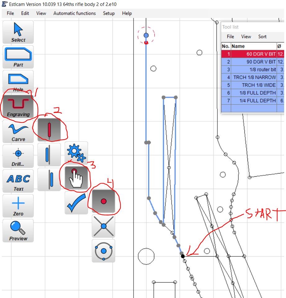
Estlcam Engraving command, 1. select command, 2. on line, left or right of line 3. Recognized lines or dot to dot 4. Dots, intersections or center points.
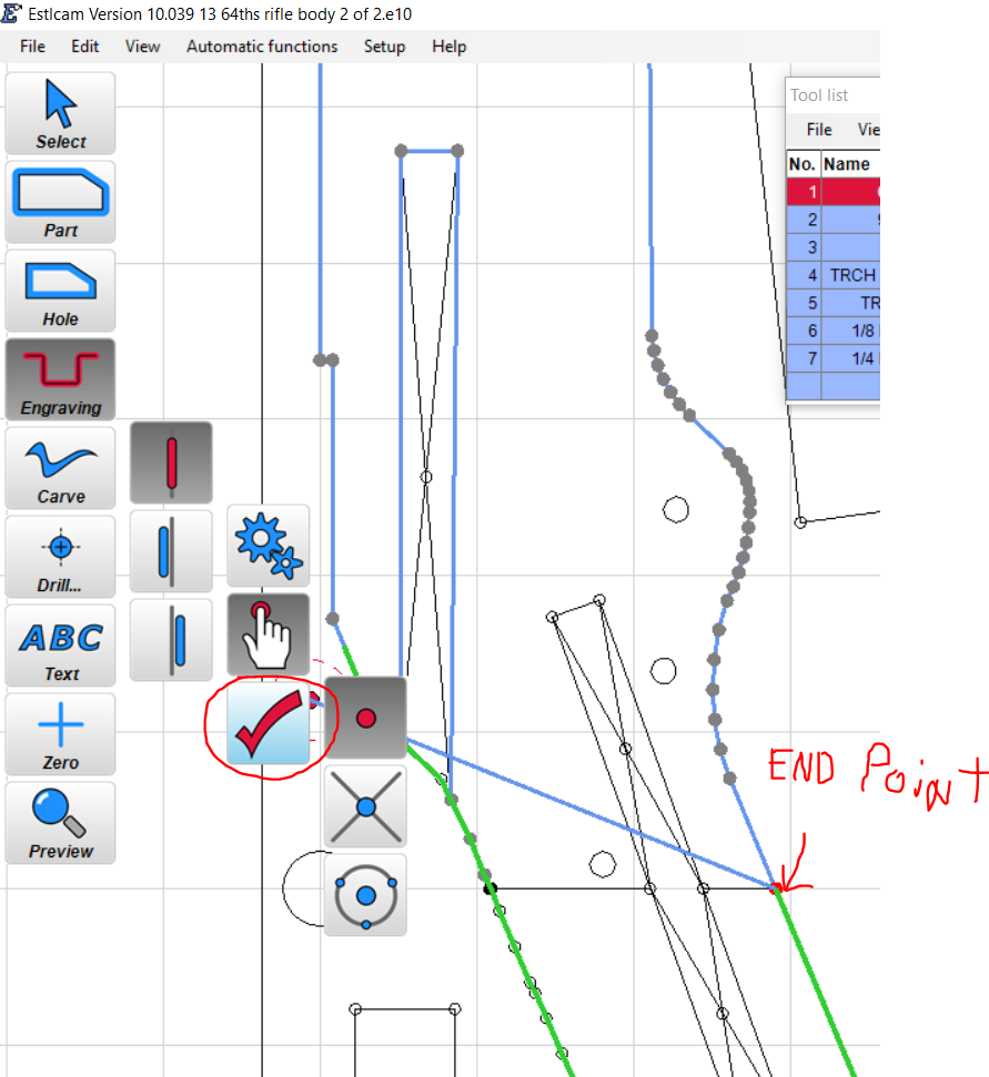
When you get to the other end, select the “check mark” to close your selection and complete an engraving tool path. The green line simply shows an expected path you can continue with. The blue line is the tool path.
The first cut I do with my cut file is to drill the 2 alignment holes. They will be important when cutting the 2nd half of the panel.
It is important to note that I create 2 cut files, 1 for each half of the panel. Since both halves are created from the same drawing, all 3 holes are in perfect alignment for each half of the panel. The side alignment holes than allow a perfect 180 degree rotation of the panel for cutting the second half of the panel.
The two cut files, 3 alignment holes, starting and end points of the patterns and the pattern in full are all rotated together so no misalignment can occur. The second half is rotated, placed over the 2 side alignment pegs and you have perfect alignment of the 2nd half with the 1st half.
The 2nd Estlcam cut file simply starts where the 1st left off and continues the cut.
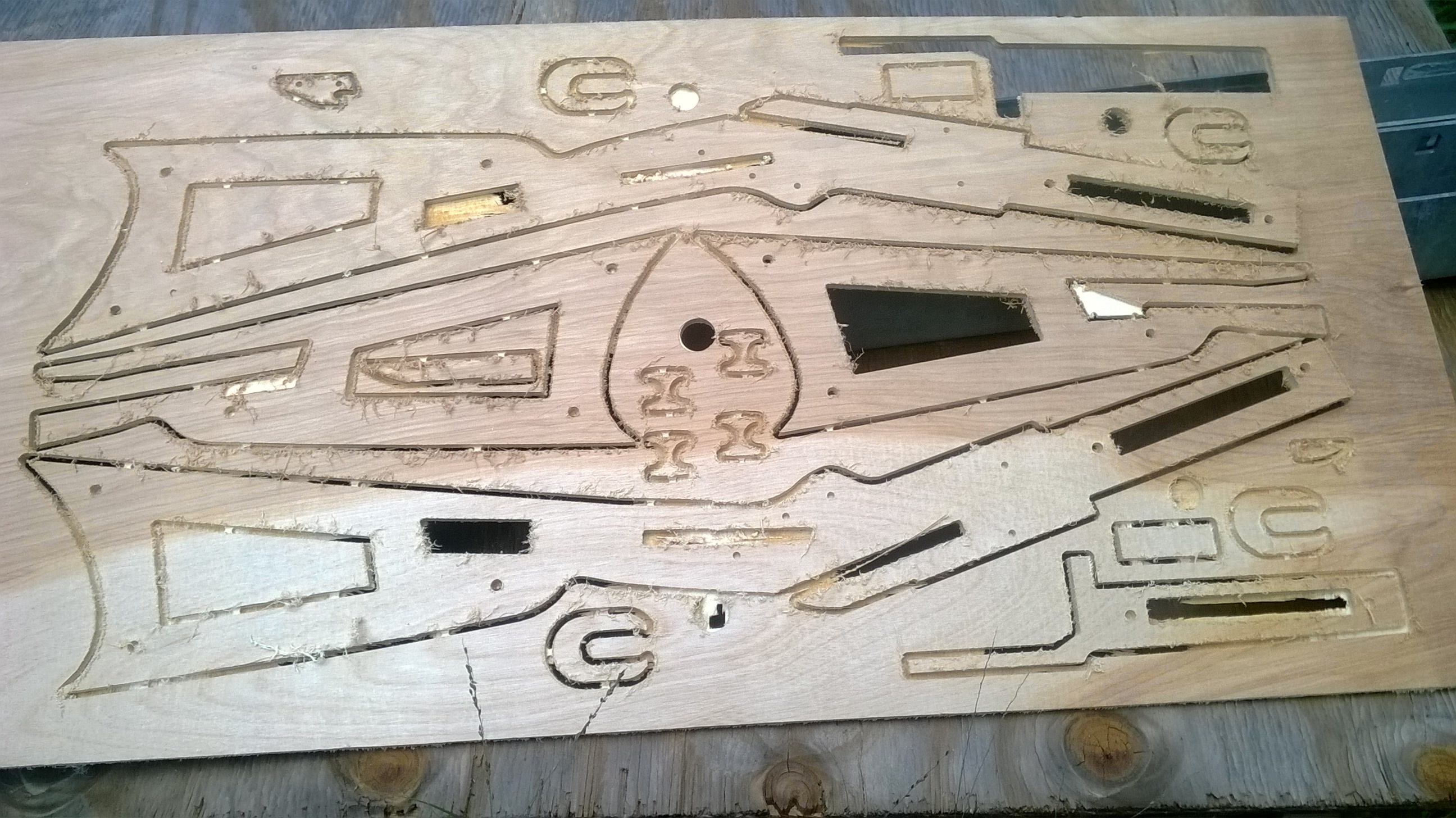
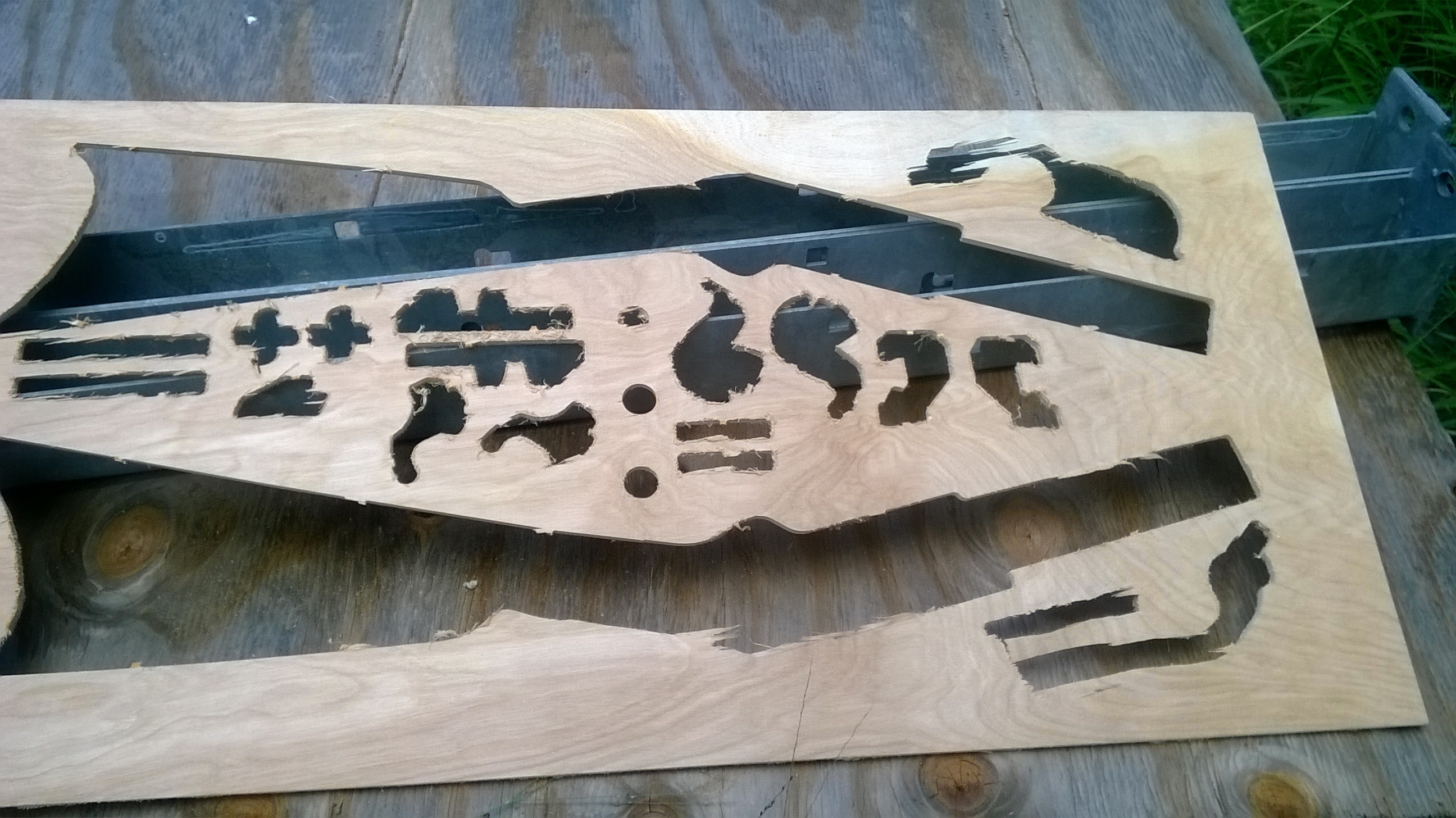
The next pictures are of a panel cut and a panel with the parts popped out.
It is just that simple. I hope this is useful to you.
Project Note: There are rubber band gun patterns on the internet, but my experience trying to use them is that they are not accurate to the point that they were useless to me and I drew and designed my own design. They make a good starting point and are great for learning how the mechanisms are intended to work but they will require more effort making the parts fit and work than is reasonable. I have not copied their designs and I do not expect or allow my designs to be copied.
I do not allow this tutorial to be shared on the internet in any other way. It is for the personal use of my fellow members of the Carbide3D Community Forum only and any misuse of this tutorial shall be severely frowned upon. Have fun and always look for the simple answer first.
This is my back edge of panel clamp to hold the middle of the panel better, helps but does not solve raising while cutting.
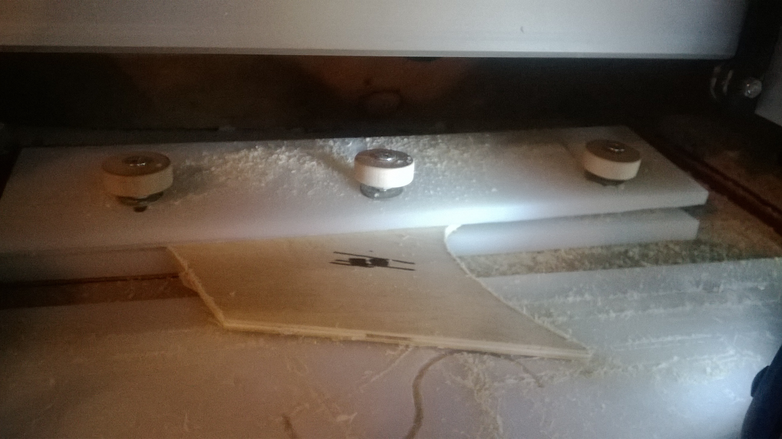
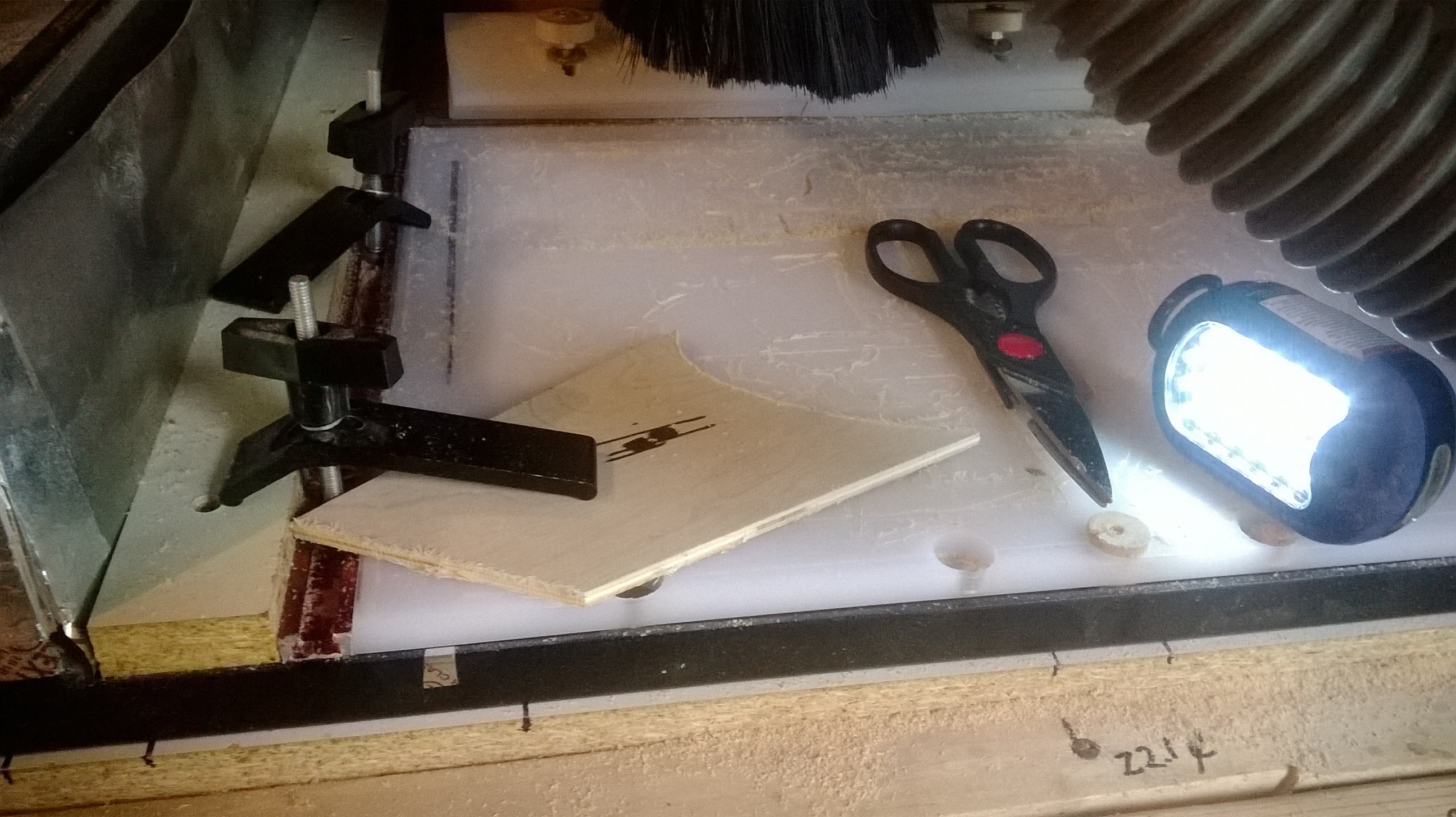
My SO3 waste board , sissors point at center peg, out side of t track is higher than material so clamp holds down pressure. Siisors point at misc side alignment holes.