Triggered by the discussion in this thread
I thought it was worth going back and re-watching a few of the handy YT videos on keyhole cutters in Fusion from NYCCNC and Portland CNC, Autodesk and others and seeing what the options are for undercutting slots in Fusion CAM. There is rarely only one way to achieve something in CAM.
I started off with a sample body which had three features of interest
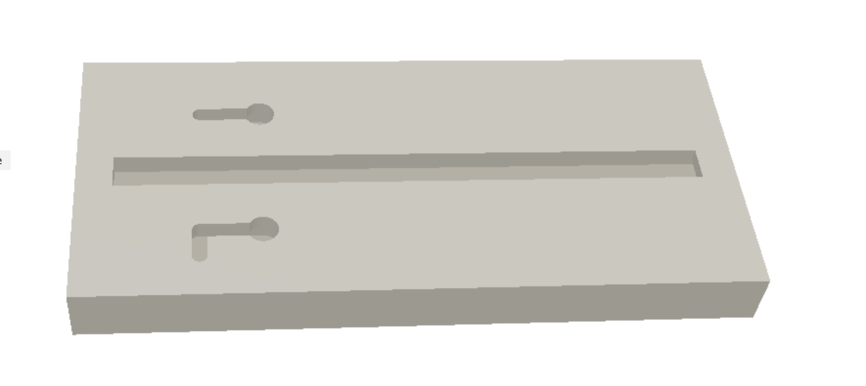
There’s a slot with an undercut all around down the center, the slot is wide enough for the fat end of the keyhole cutter to plunge in. A regular keyhole slot above and a dogleg keyhole slot below, don’t ask me what a dogleg keyhole slot is useful for, it’s a variation which has a non-straight slot…
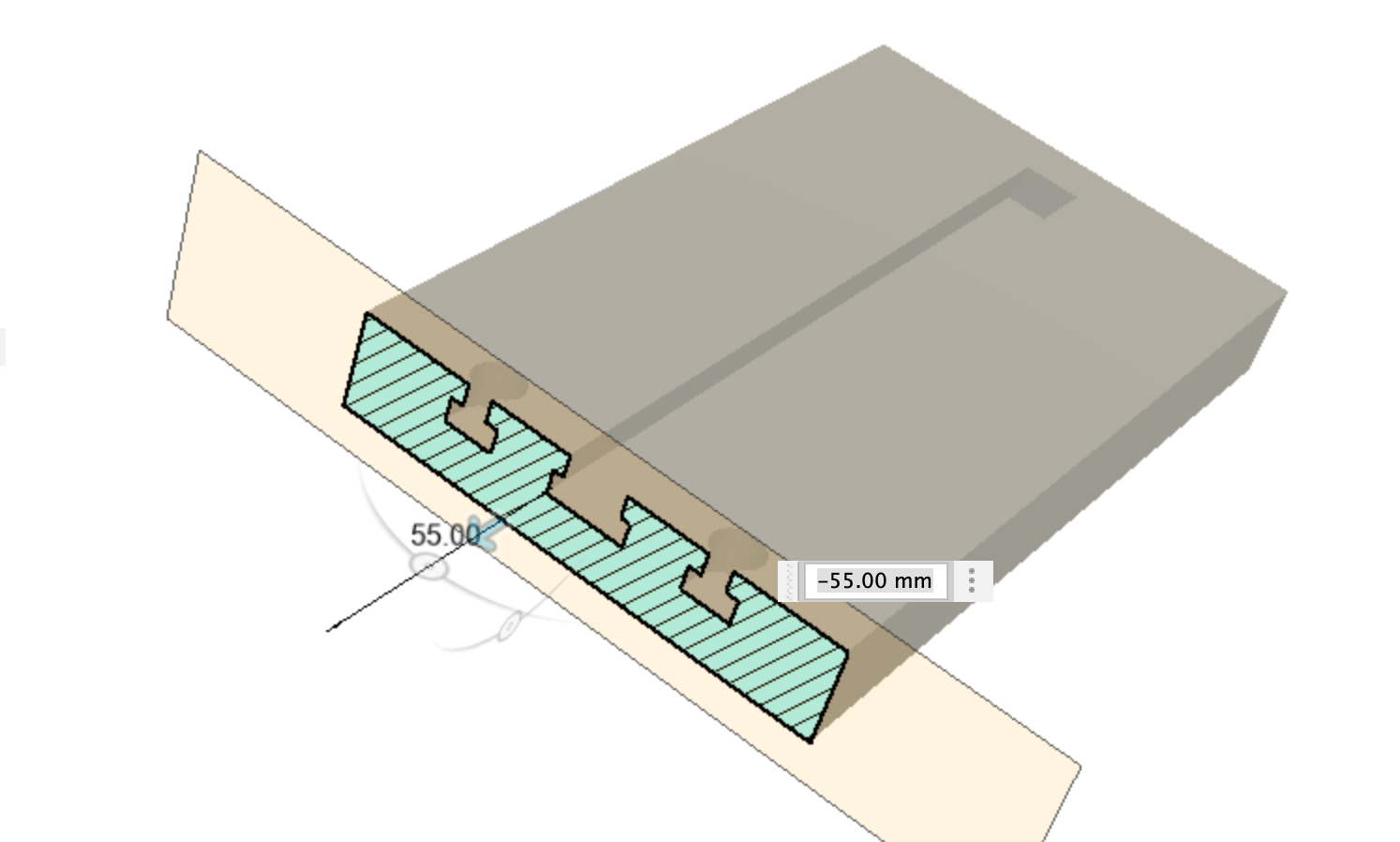
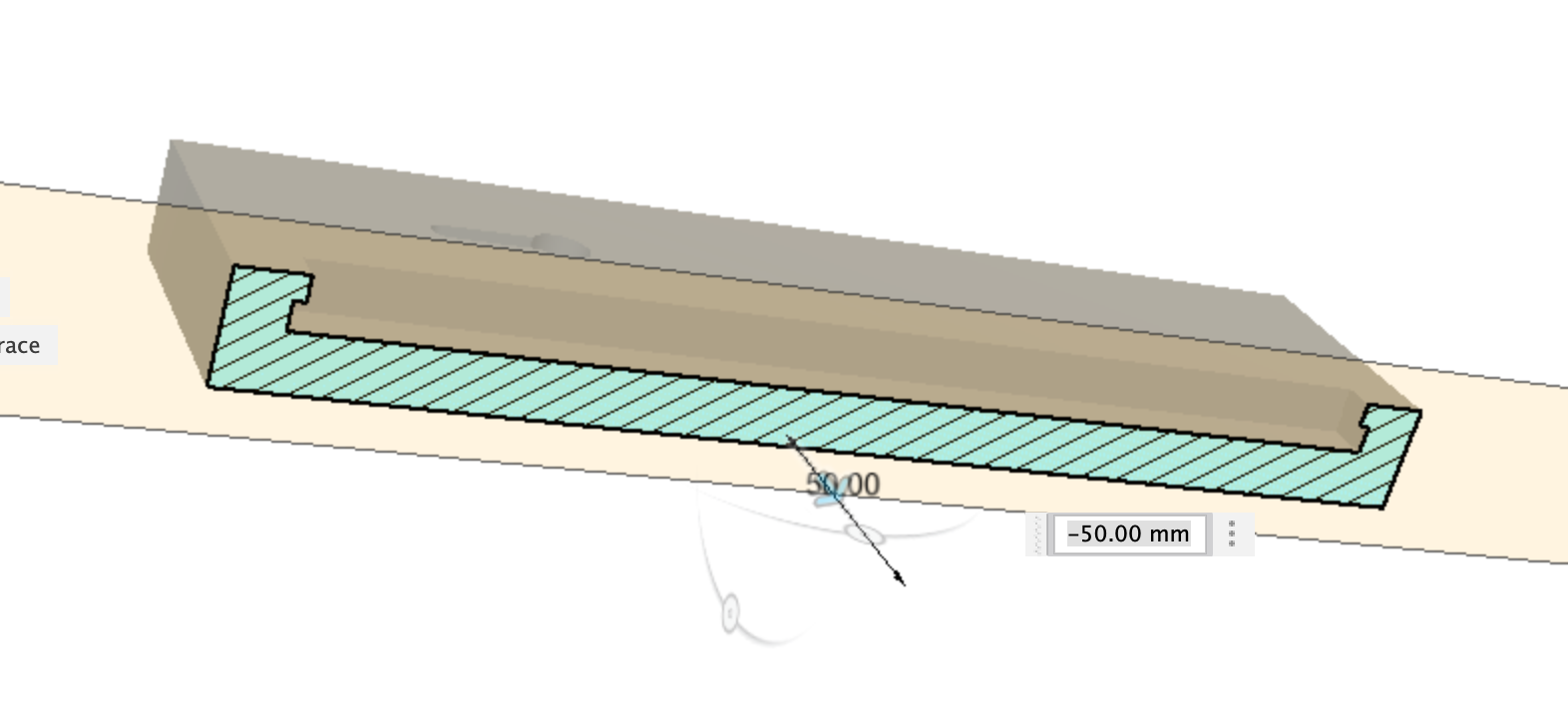
Center slot has undercut at the ends as well as the sides
Dogleg slot with keyhole undercut

Once we have a body to machine we need a tool in the tool library, this was trickier than I expected it to be, I saw quite a few examples of a keyhole cutter being set up, but none with the wider shank above the cutter area.
I’m using this cutter
Which has a 9.5mm keyhole with a 4.5mm narrowed section below a 1/4" (6.35mm) shank. I’d like to see that in the CAM simulation and know if I’m crashing the shank into the workpiece etc.
It’s easy enough to set up the basic cutter, select a Slot Mill as the cutter type and put in your cutter dimensions

The problem is there’s nowhere here to tell Fusion about the 1/4" fat shank sticking out the top of the cutter. Unless you figure out what the Shank tab is for, I’d never used it before, but if you put numbers in then it’s easy enough to figure out some basics.
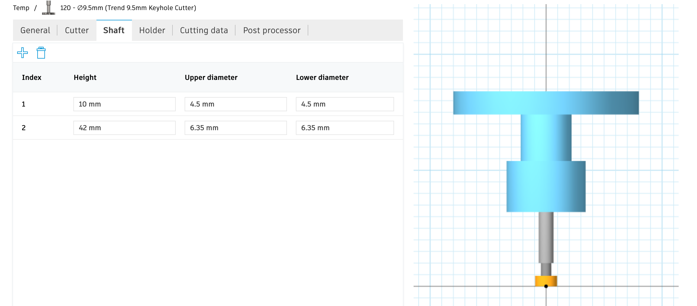
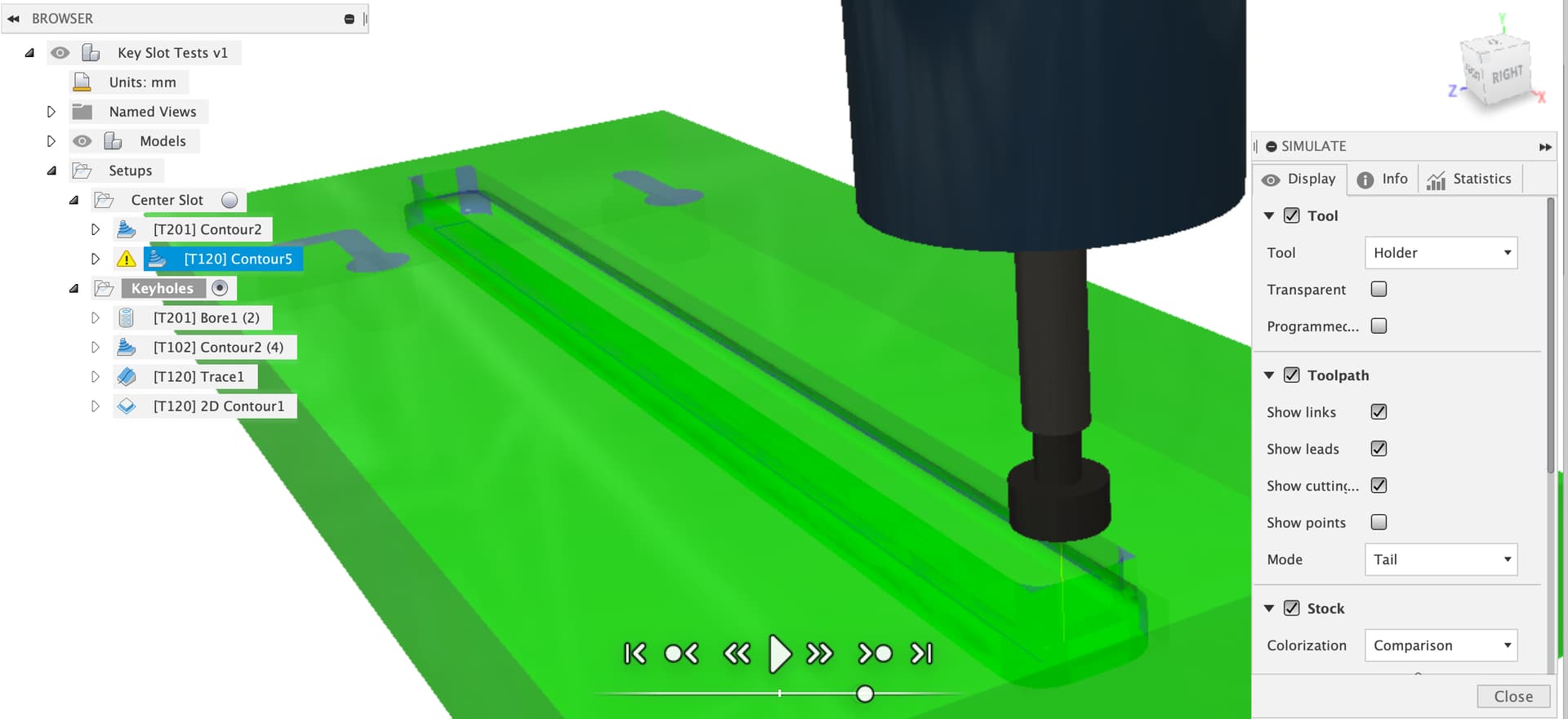
And now we have the 1/4" shank, the 4.5mm narrow section and the 9.5mm wide slot cutter section so we can use 3D toolpaths or run CAM simulations and get useful results like collision warnings.
CAM
Starting with the slot, we can use a 3D contour toolpath, regular Carbide 201 cutter with a ramp type of profile to clear the majority of the slot out and avoid breaking our keyhole cutter.
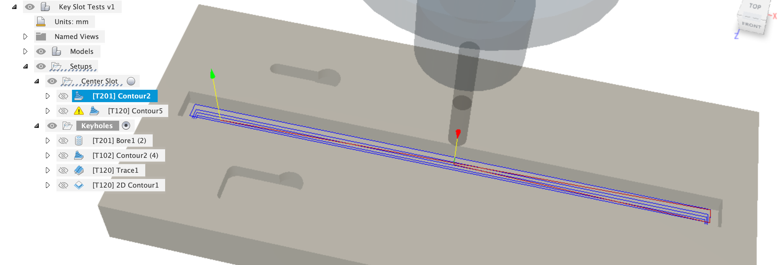
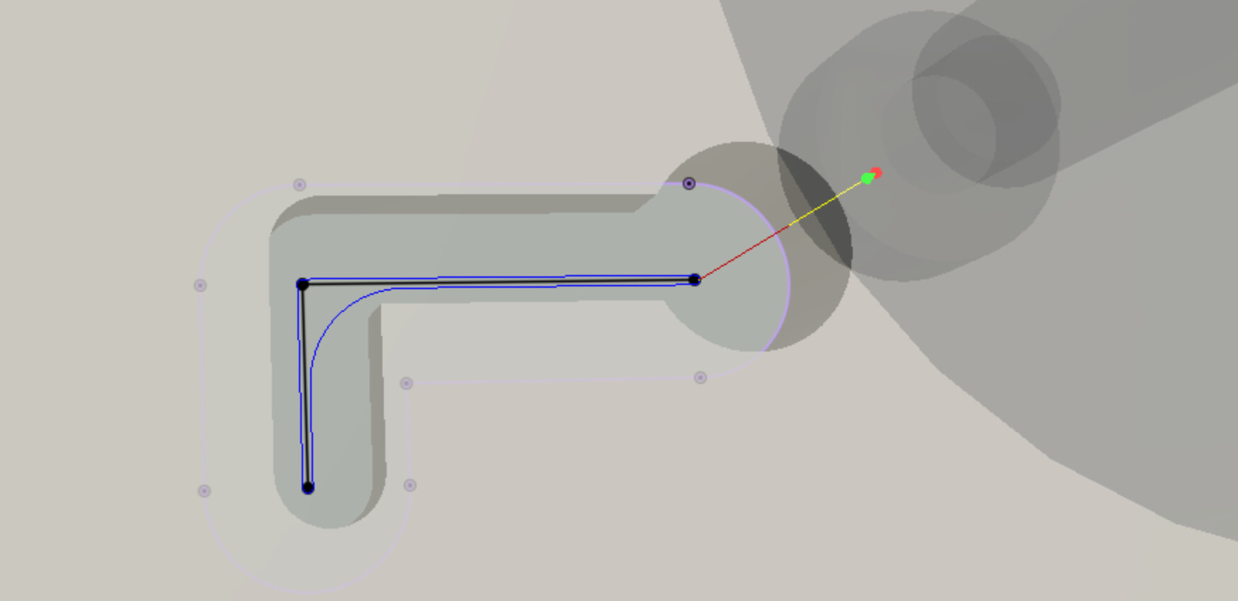
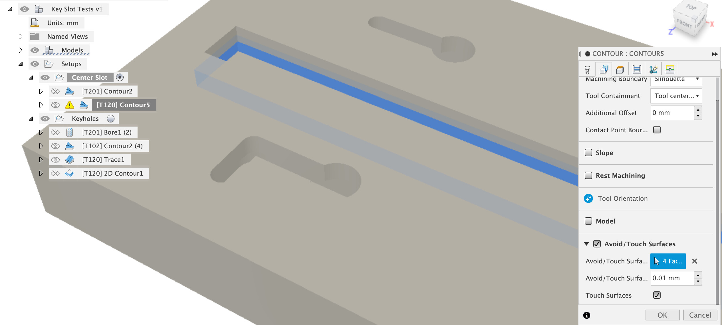
To get the undercut another 3D contour toolpath is used, this time with the keyhole cutter, and the undercut faces are selected as faces to touch
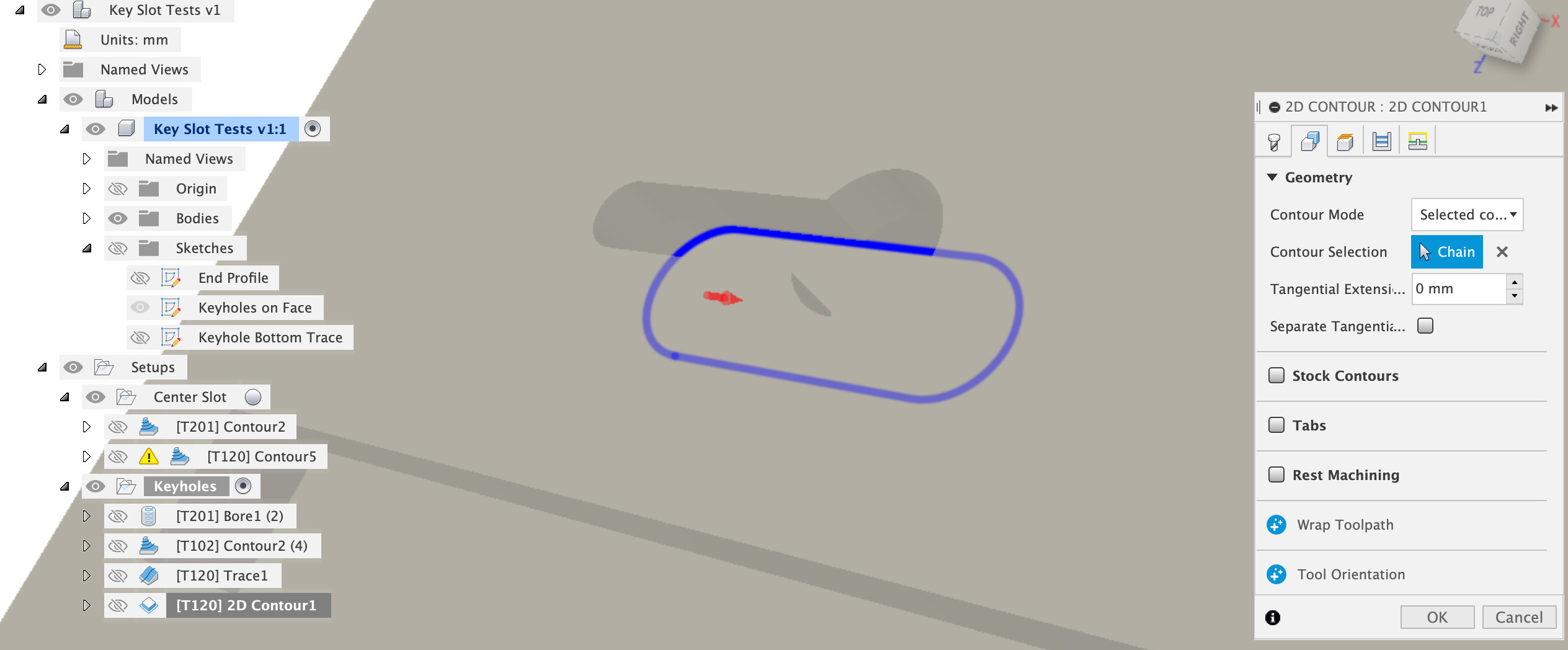
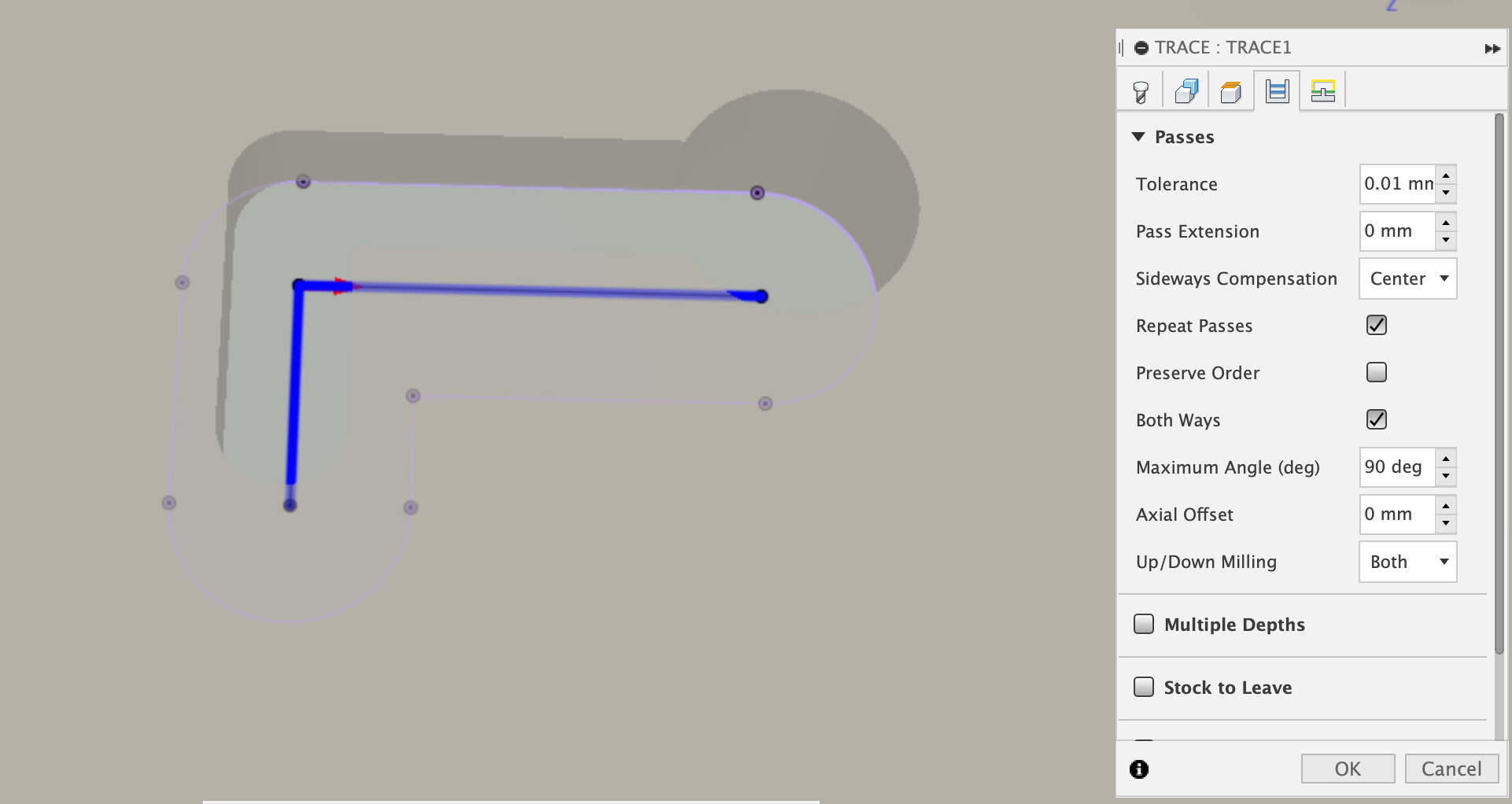
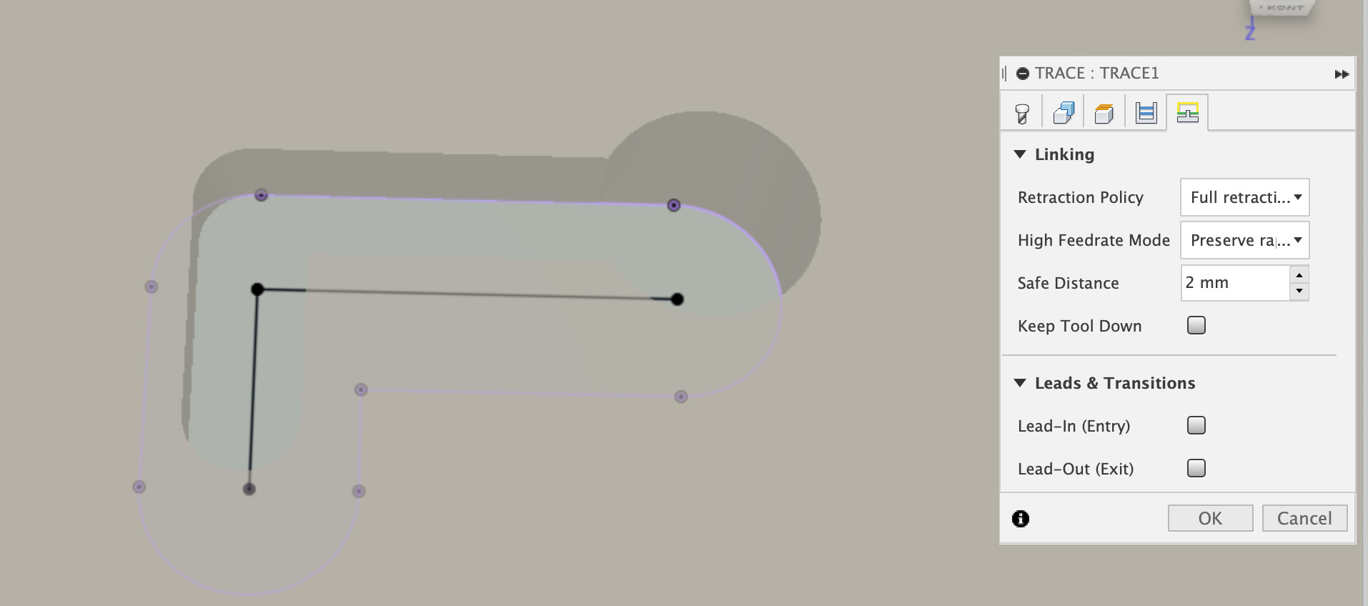
The other trick, to avoid your slot getting notched during the lead out as the tool exits is to set the lead in / out vertical radius to zero.
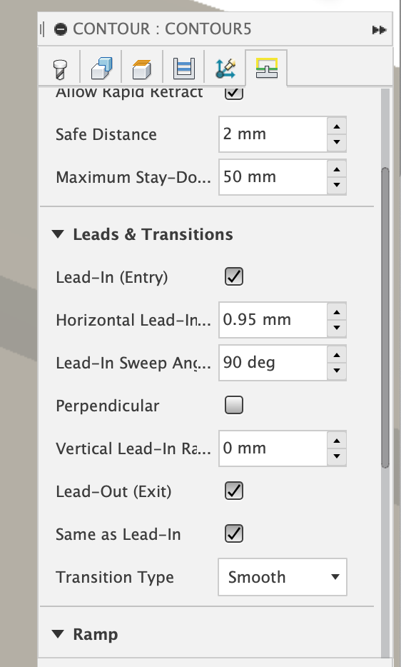
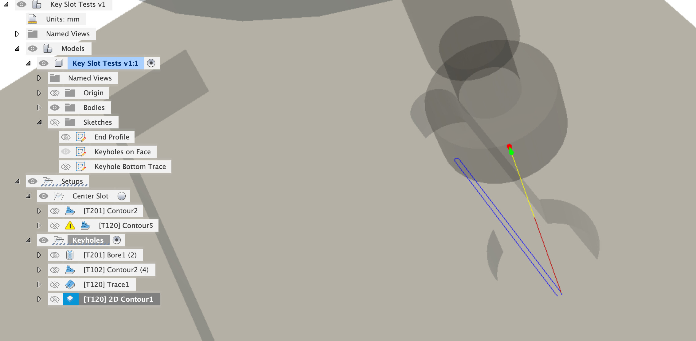
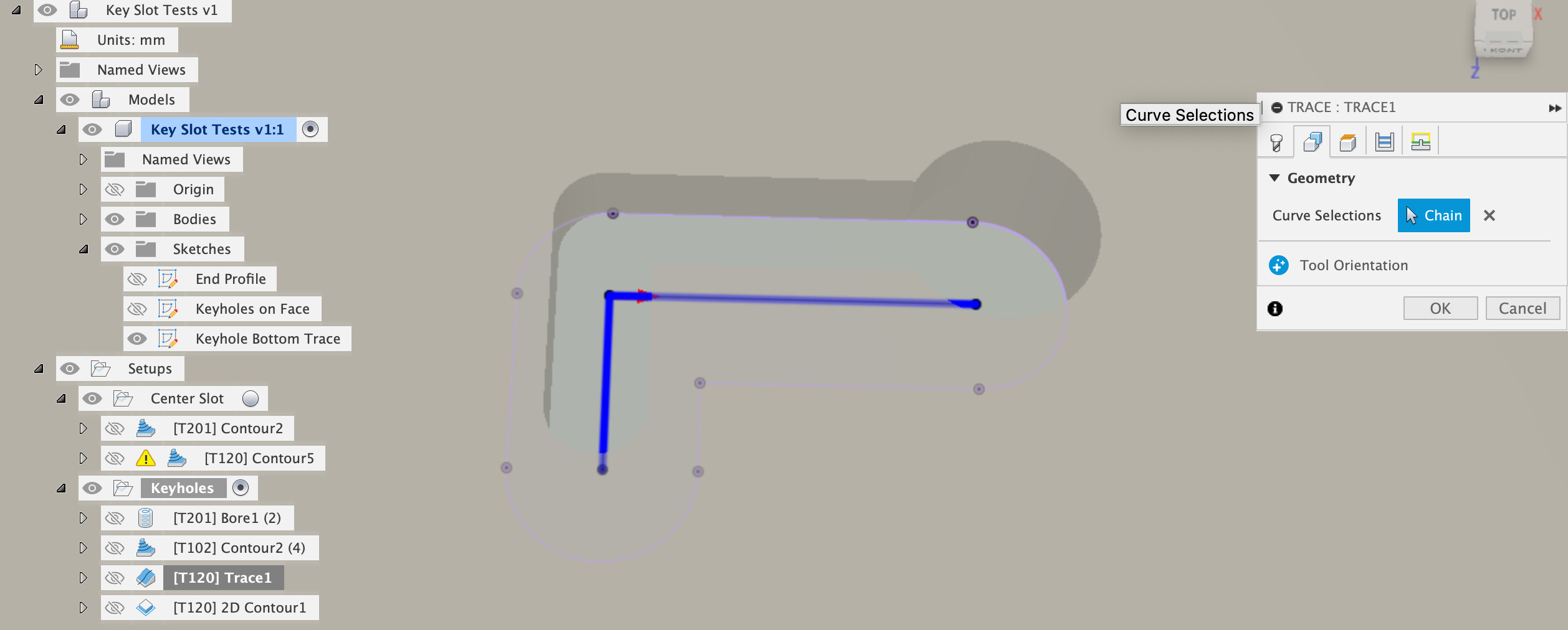
Which allows Fusion to work out the toolpath
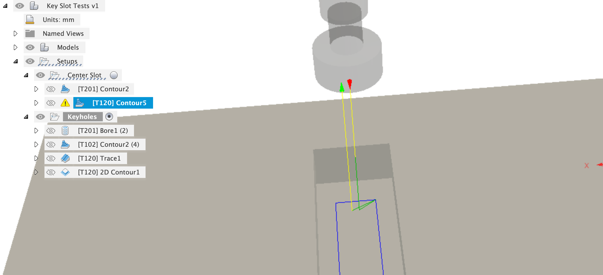
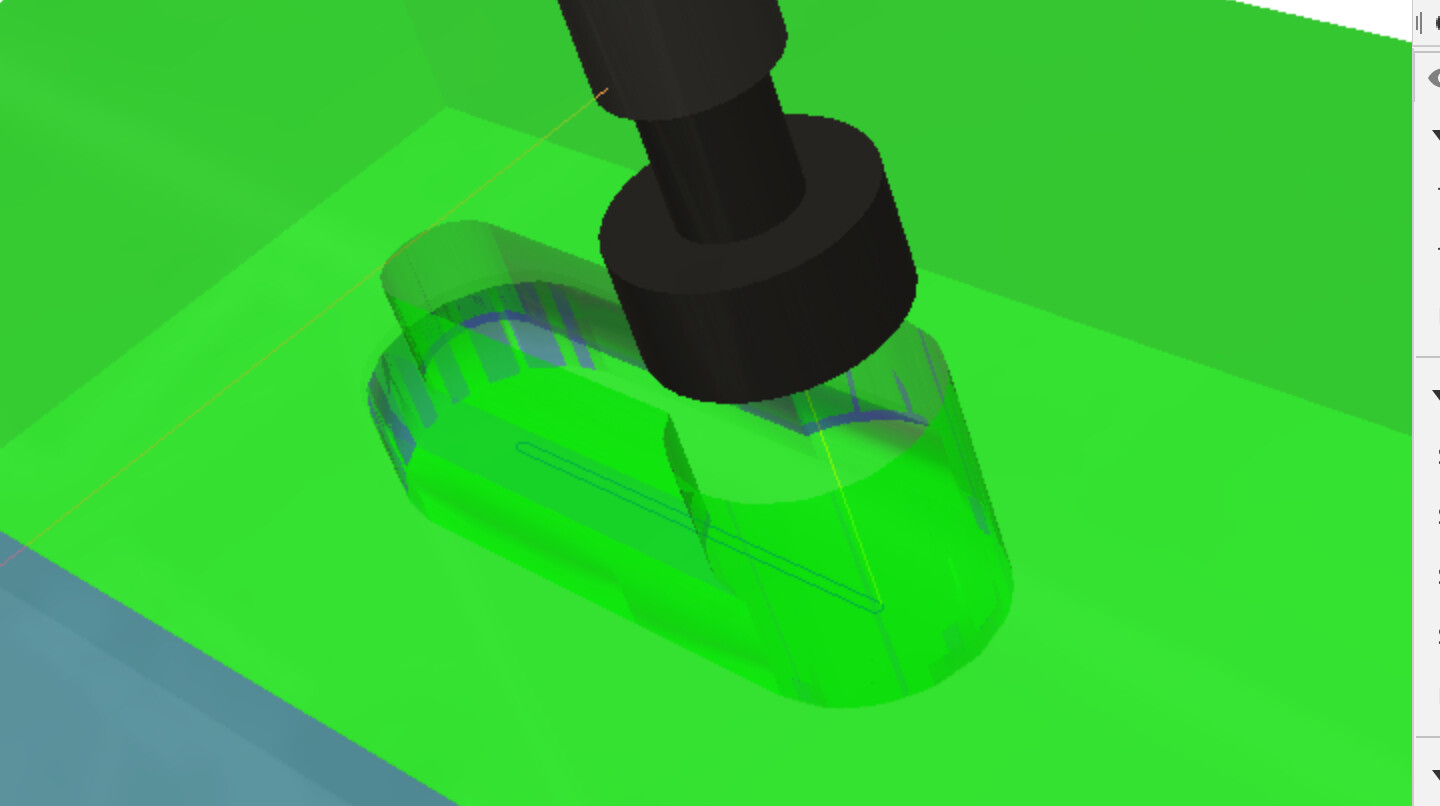
CAM simulation gives us what we’d expect, some unremoved stock in the corners due to cutter radius but otherwise, what we want, without having to draw contour sketches down the bottom of our slot or anything else.
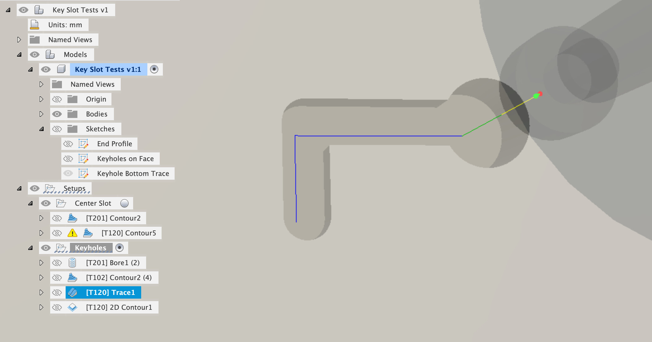
Now for the keyholes.
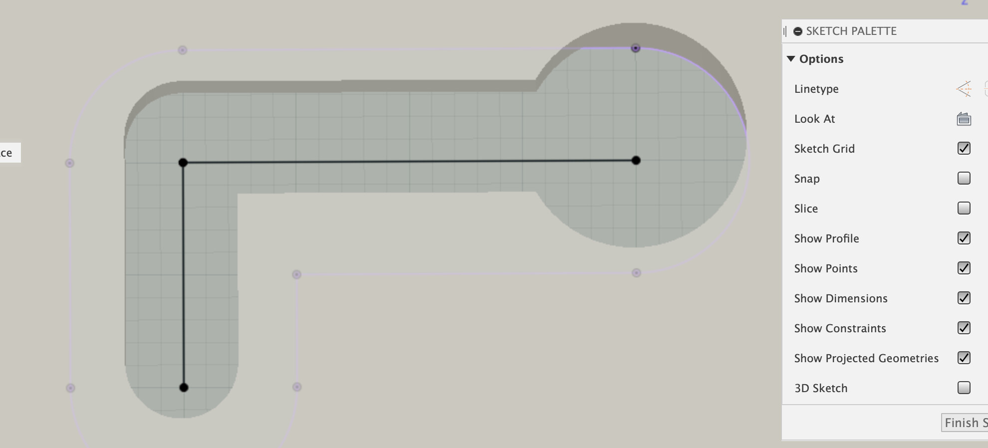
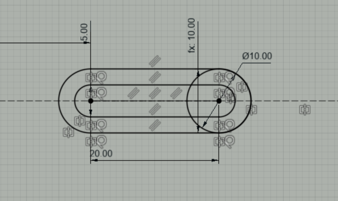
I found a reasonably quick way to create the features was to sketch a circle and then a center to center slot, using the same center as the circle
We now have features to extrude into the solid, first extrude the surface slot
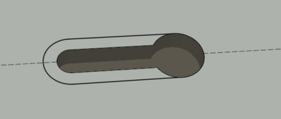
And then the lower part
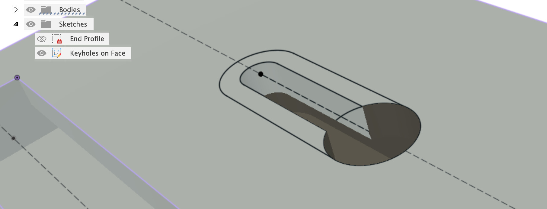
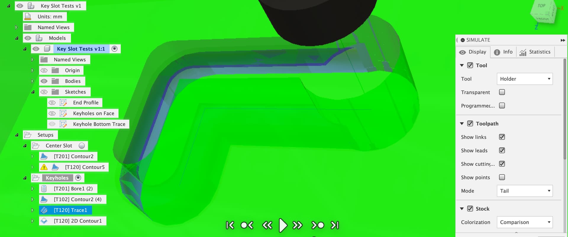
Which gives us a 3D model of the keyhole with undercut to check in CAM.
We can clear the large ends of the keyholes with a boring op, 1/4" Carbide 201 cutter

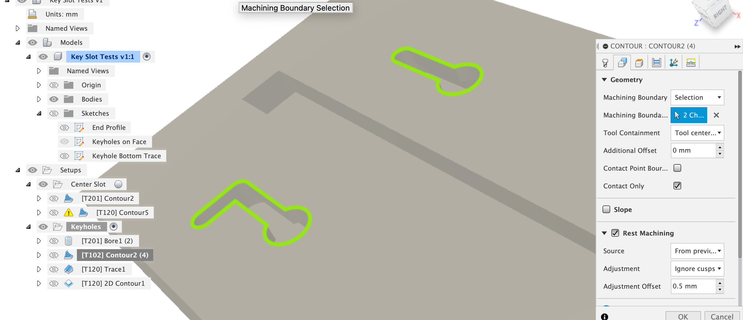
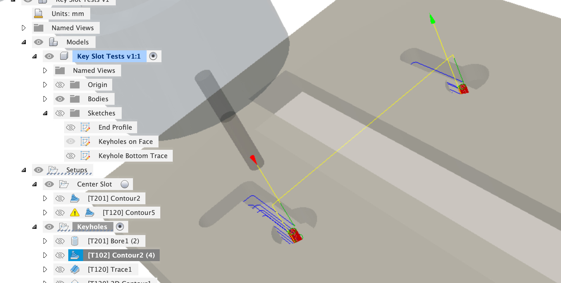
We can then pre-clear the slot with the Carbide 1/8th cutter (102). Selecting the outer contour of the keyslots as a boundary