This came up in a support e-mail — unfortunately, Carbide Create can’t preview this, but it can be done — it just takes a bit of faith:
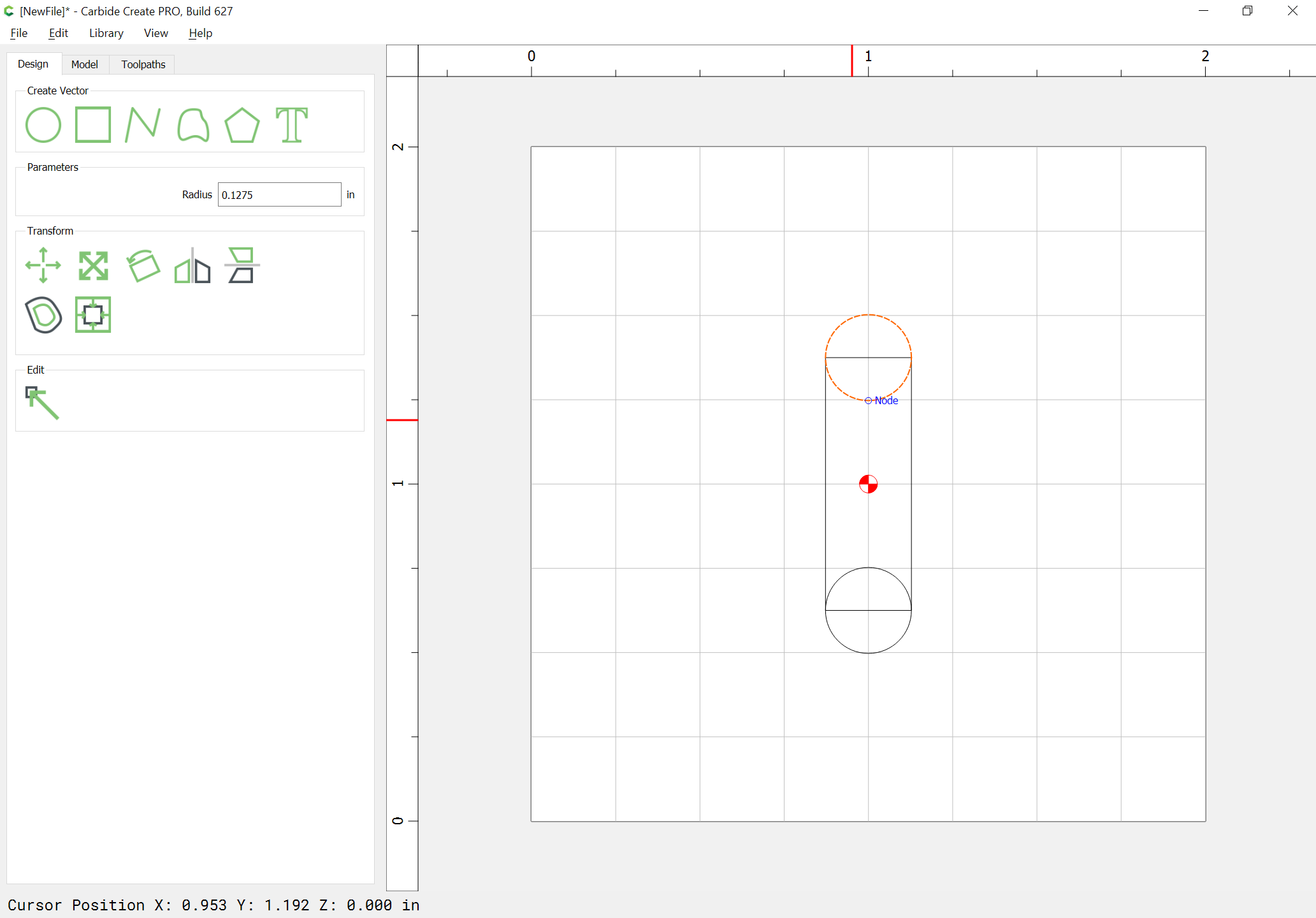
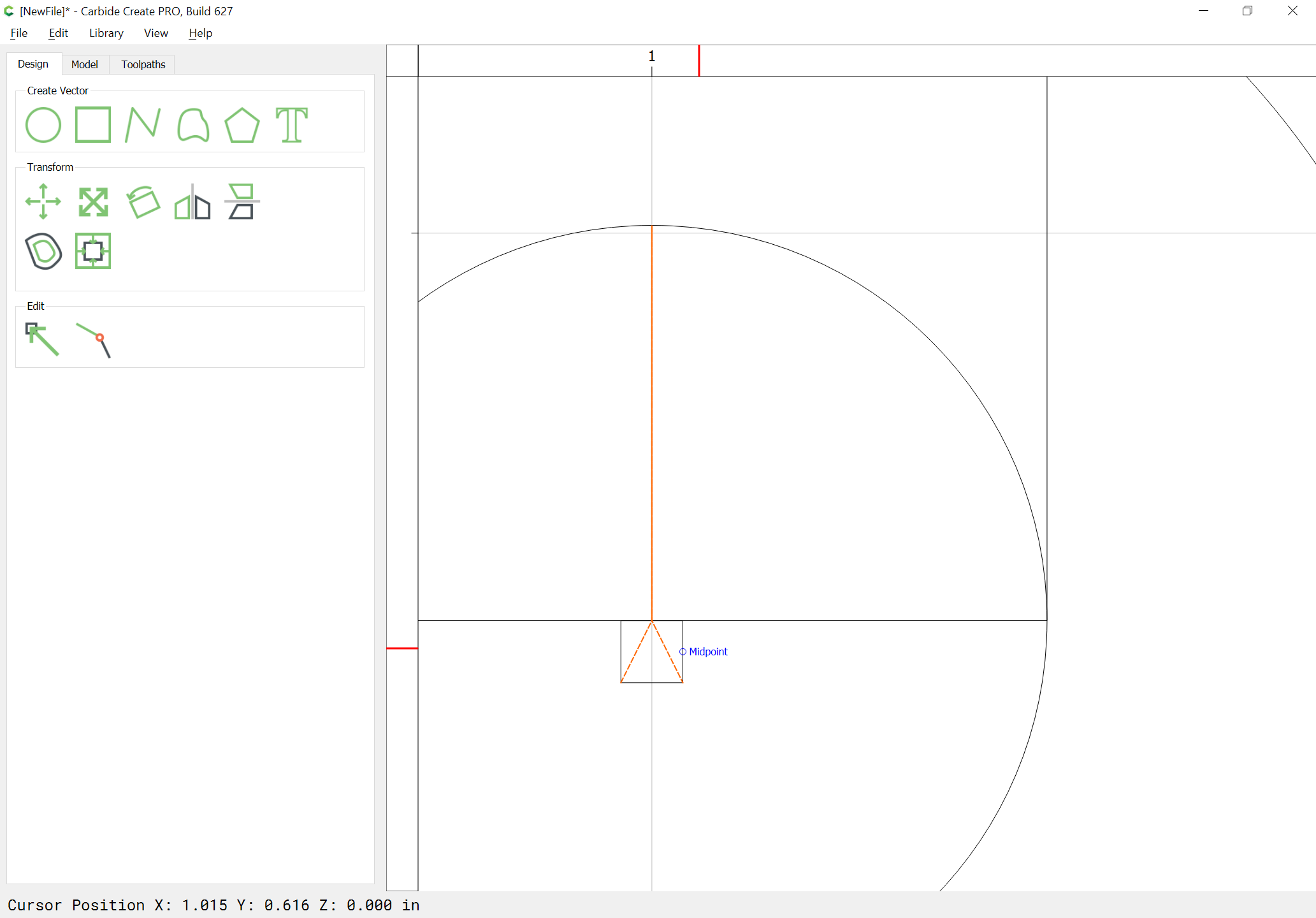
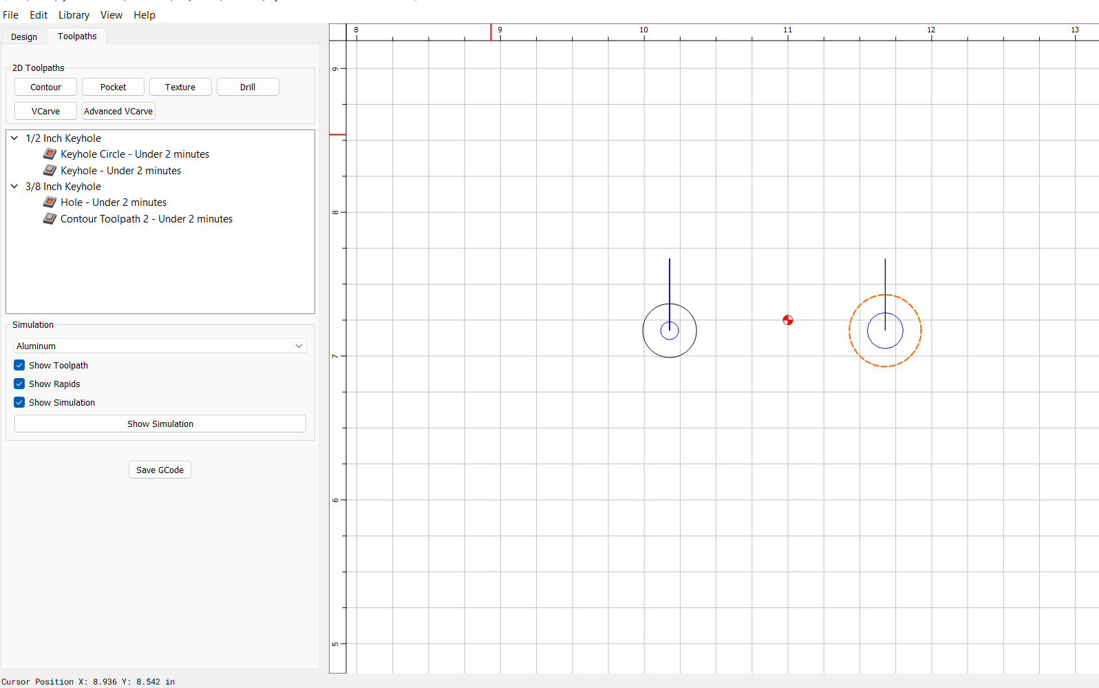
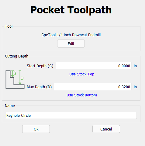
First, model the slot (the width should be a bit more than the shaft of the keyhole tool, the length equal to how long you want) — this is best done as two circles and a rectangle all connected — using a rectangle makes it easy to position the circles since one can use the midpoints:
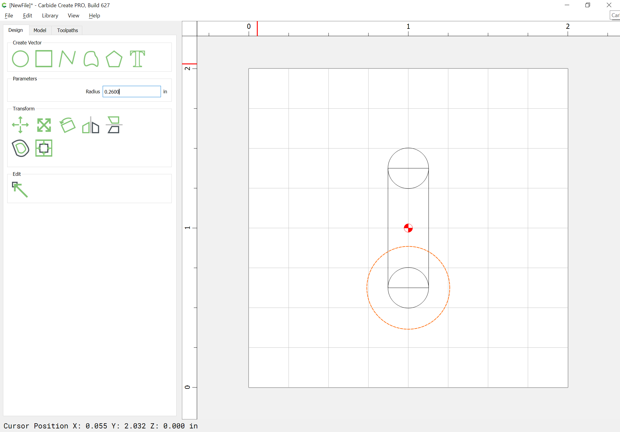
Then draw in the entry hole (this should be a bit more in diameter than the cutting portion of the keyhole tool) — it’s easy to position accurately as the afore-mentioned circles are because one can as noted above, use the midpoint:
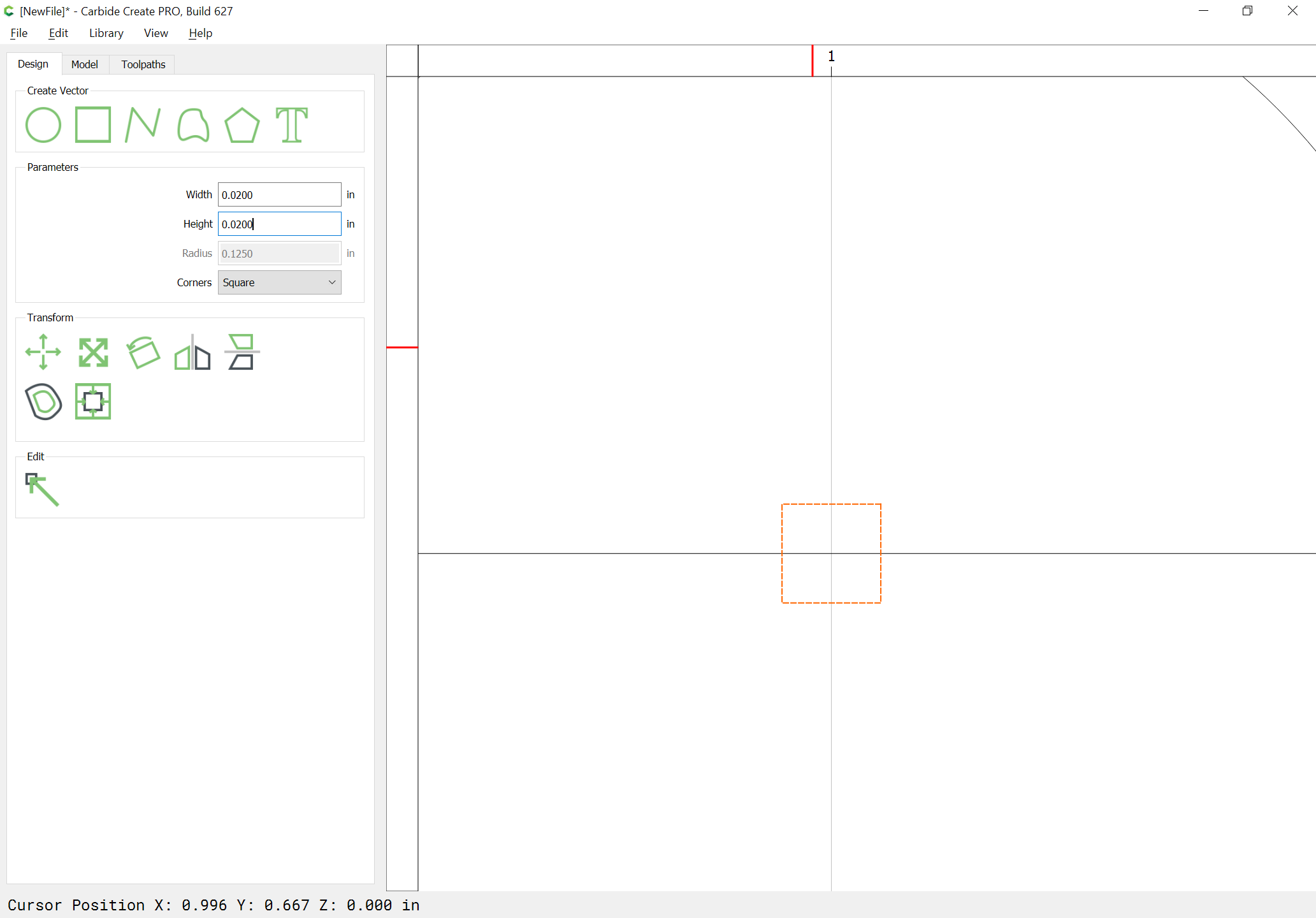
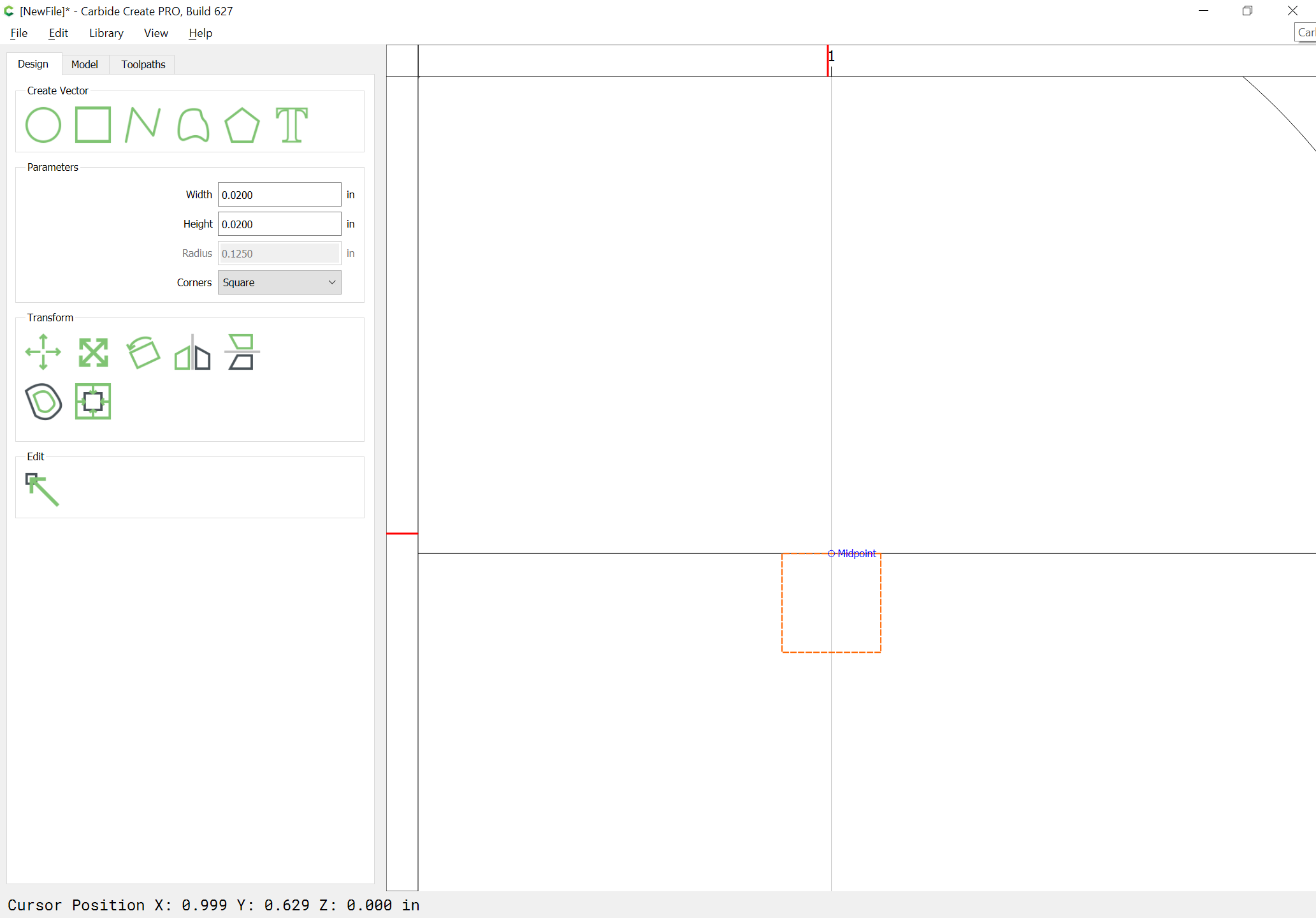
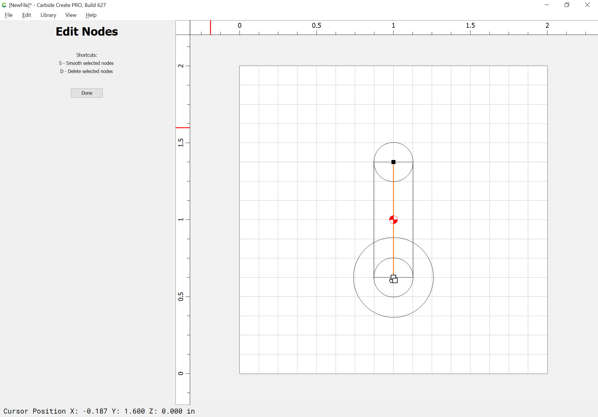
Then draw in an open Polyline which starts at the bottom left corner of the small square, goes up to the top/bottom midpoint of the square/rectangle, up to the top midpoint, and comes back down to the top-bottom midpoint, and ends at the bottom right corner — this is most easily done by zooming in and using the top of the circle as a proxy:
Note that it will be necessary to extend the bottom slot by the height of the square by duping the square and making it a rectangle as wide as the circle and dragging a duplicate of the circle down to align at the bottom midpoint center:
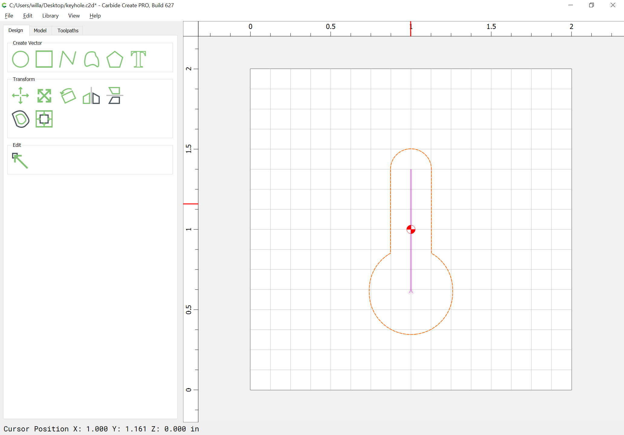
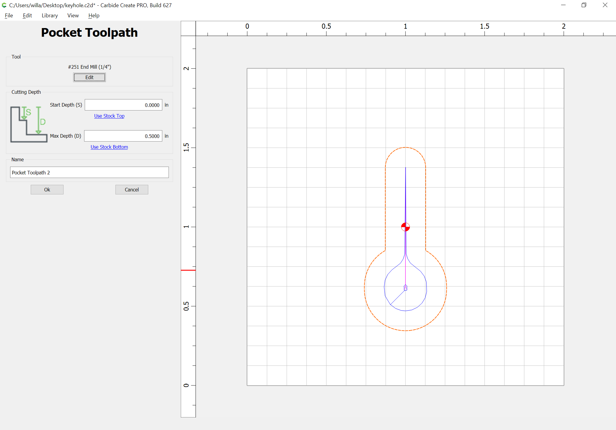
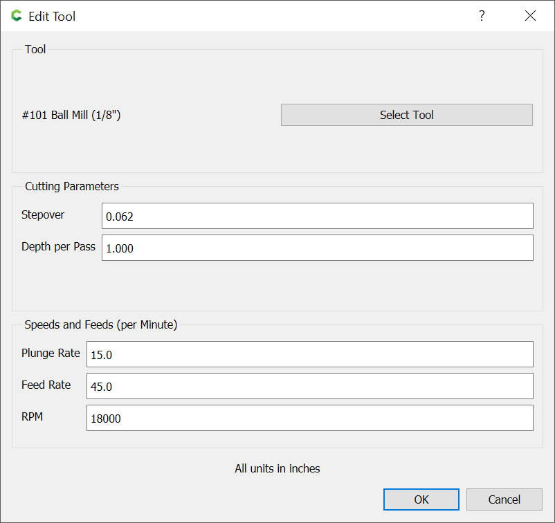
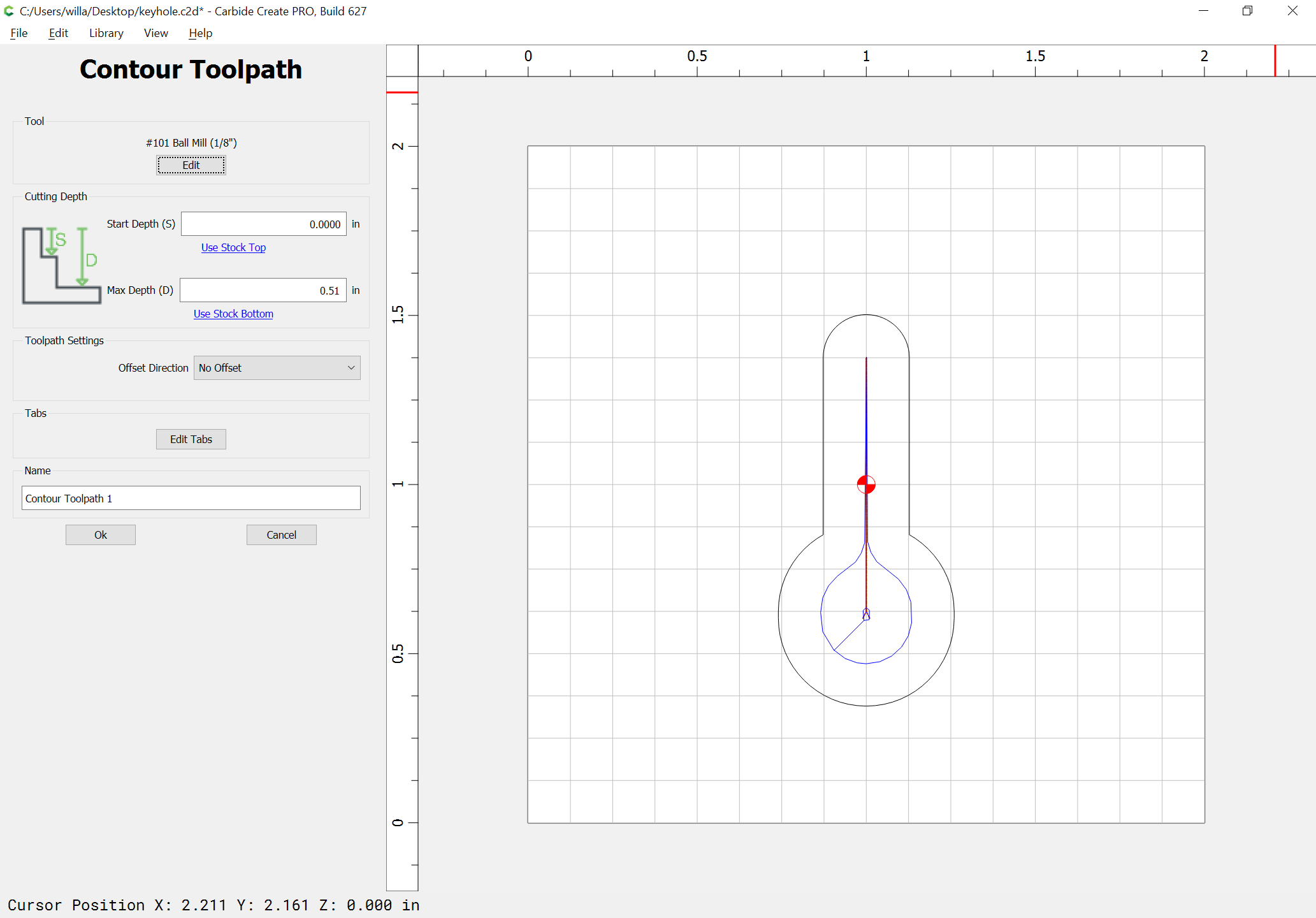
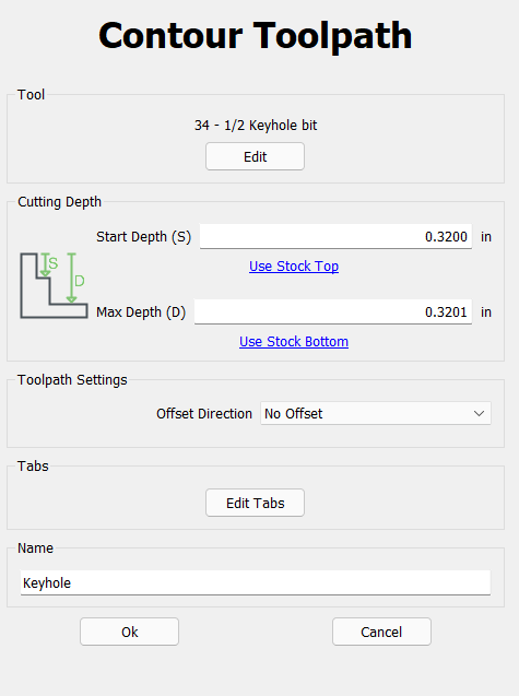
Then select the polyline and assign a different tool to make a no offset contour cut to that depth or a bit deeper — I like to use a ball-nose endmill and a bit deeper so that I can see the cut and assign a Depth per Pass greater than the depth of the pocket so that it will be cut in a single pass:
Specifically, a plunge, move in a specific direction, move back in the opposite direction and raise out?
Thinking while typing maybe a thin dual line path?
I think I know how to put this tool in CC but would be interested in your input.
That definitely looks better in the preview than mine does but I went far simpler for the keyholes. I did a circle with a simple pocket and then a polyline with one end at the centre of the circle.
As long as the polyline started ad the centre of the circle it would go up the line then back to the circle and retract. It feels like it should not work but so far it has for me. I half expected it to retract at the end of the polyline and cause me to have the tool rip out of the wood or cause the z-axis to skip steps. i have not done this in a while so do you know if the newer versions of Carbide Create will make my method stop working @WillAdams?
More seriously, for Fusion 360 users you have to do basically the same thing, everything I’ve found so far says to use the 2D trace toolpath and draw what you want the cutter to do.
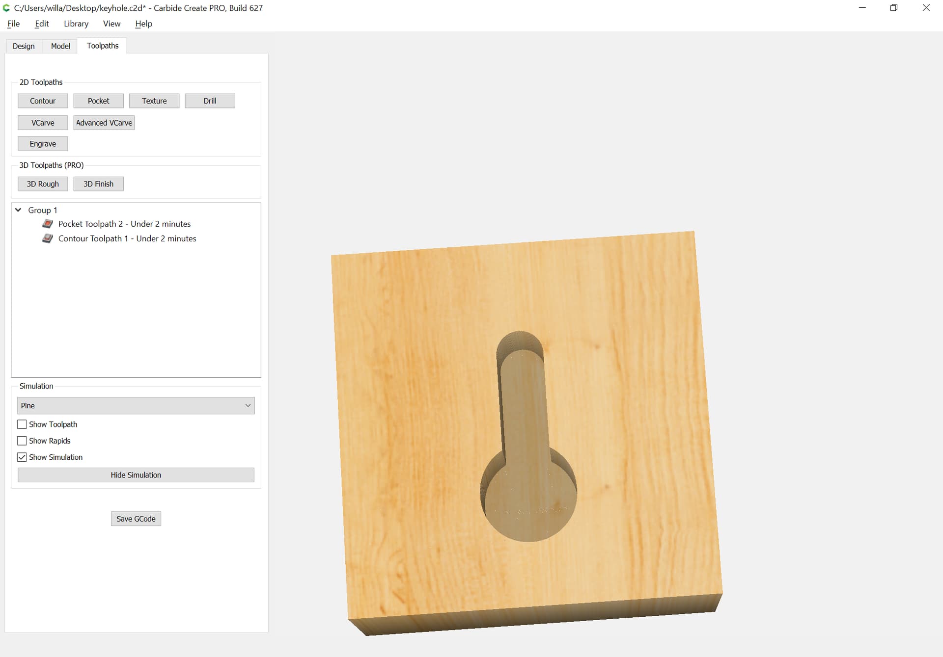
When I looked at the CC file, I see the ball nose in the slot from the top to the bottom.
Where does the Keyhole cutter stay at the bottom of the pocket and follow the slot both ways?
The toolpath for the ball-nose (which is used for the keyhole tool) is set to go to full depth because of the setting of the depth per pass for that toolpath to greater than the depth of the pocket.
DISCLAIMER: I AM JUST STARTING TO LOOK AT GCODE AND EDITING THEM MYSELF IN NOTEPAD SO THIS IS UNTESTED AND MAYBE SOMEONE WITH GCODE-FU CAN TAKE A LOOK AND COMMENT/MODIFY AS NEEDED.
I looked at the GCode in NC Viewer only and it appears to do what I expected it to do. Please do your due diligence and look at it yourself in something like NC Viewer and/or aircut if you are going to use this as a starting point.
Make sure the keyhole bit is higher than the work piece and X,Y,Z has been zero’ed at the top of the stock where you want the keyhole bit to enter the stock
The bit will do a pecking operation in the Z direction descending in 3mm increments (0, 3, 6, 9, 10) until it gets down to 10mm. Depending on the bit and how deep you want the keyhole to descend into the stock this would need to be edited
Once the Z axis has pecked to its full depth it will then move in the Y direction. The slot will be cut towards the front of the table and like the Z axis movement the bit will do a pecking like motion until it reaches the full length of the slot. In this example its 15mm
The bit will then return to X=0, Y=0 and then proceed with pulling back out of the stock by 15mm and as the Z axis pecking operation went down 10mm this means at the end of the operation the keyhole bit will be 5mm above the stock.
(EDIT: SOME EDITS MADE BASED ON @neilferreri COMMENTS BELOW
(KEYHOLE GCODE WITH A PLUNGE OPERATION, Z DEPTH = 10mm AND SLOT LENGTH Y = 15mm)

G90			(G90 so these are absolute values meaning all X,Y,Z values are in reference to you absolute Zero (X=0, Y=0, Z=0 location)
G21			(Metric so measurements are in mm)
G0 Z5.000		(Move Z to 5mm above Z-Zero - should be high enough to clear clamps to be safe)
G0 X0.000 Y0.000	(Move to X=0 and Y=0 if not already there, this is the location that the keyhole bit will enter the stock)
G1 Z-3.000 F200.0	(Start Plunge/Pecking operation, if you want to adjust the plunge/feedrate change the number after 'F' in mm/minute)
Z-0.000			(Remove this line if you do not want to do the pecking operation in the Z direction)
Z-6.000			(Remove this line if you do not want to do the pecking operation in the Z direction)
Z-0.000			(Remove this line if you do not want to do the pecking operation in the Z direction)
Z-9.000			(Remove this line if you do not want to do the pecking operation in the Z direction)
Z-0.000			(Remove this line if you do not want to do the pecking operation in the Z direction)
Z-10.000		(End of Plunge/Pecking operation in the Z axis and change this Z value to the final depth you want the keyhole bit end up at in mm)
Y3.000			(From bottom of pocket currently -10mm start plunge/pecking in the Y direction in increments of 3mm Y=0,3,6,9,12,15)
Y0.000			(Remove this line if you do not want to do the pecking operation in the Y direction)
Y6.000			(Remove this line if you do not want to do the pecking operation in the Y direction)
Y0.000			(Remove this line if you do not want to do the pecking operation in the Y direction)
Y9.000			(Remove this line if you do not want to do the pecking operation in the Y direction)
Y0.000			(Remove this line if you do not want to do the pecking operation in the Y direction)
Y12.000			(Remove this line if you do not want to do the pecking operation in the Y direction)
Y0.000			(Remove this line if you do not want to do the pecking operation in the Y direction)
Y15.000			(End of pecking operation in the Y axis and chang this Y value to the final length you want your slot in mm)
Y0.000			(End of slot cutting in the Y direction and returning to X=0, Y=0)
Z5.000			(Retract from the pocket in the Z direction from where the keyhole bit first entered into the stock to Z=5mm)
M02
This is meant as just a starting point, maybe someone that is well versed in GCODE can take a look at it and suggest changes to clean it up as needed.
(EDIT: I’m not 100% sure this would be run in mm and not in inches but like I said I’m just starting to look at GCode so help needed to confirm that part)
(EDIT: Also in addition to confirming this would run in mm’s you would also need to edit the plunge/feed rates to make sure this is correct for your tools. In this example it’s the F200.0 meaning 200mm/m I think…)
If we have a small GCode file to do the keyhole operation is this something that we can use in Carbide Motion as a macro/quick action and have it saved in a library of operations so it’s permanently there ready to run?
Some comments below. (in parentheses)
I’ve done similar with KeyHoles, but I used G91 mode, so I could just jog to the location I wanted the slot and run the code from there.
G90
G21
G0 X0.000 Y0.000
G0 Z0.0 F200.0 (G0 is a rapid move, feedrate not needed.  I wouldn't rapid to Z0 anyway)
G1 Z-3.000 F200.0
G1 Z-0.000 F200.0
G1 Z-6.000 F200.0
G1 Z-0.000 F200.0
G1 Z-9.000 F200.0
G1 Z-0.000 F200.0
G1 Z-10.000 F200.0
G1 X0.000 Y3.000 F200.0 (G1, X0, & F200 are redundant, but doesn't affect anything really)
G1 X0.000 Y0.000 F200.0	(Feed seems really slow?)
G1 X0.000 Y6.000 F200.0
G1 X0.000 Y0.000 F200.0
G1 X0.000 Y9.000 F200.0
G1 X0.000 Y0.000 F200.0
G1 X0.000 Y12.000 F200.0
G1 X0.000 Y0.000 F200.0
G1 X0.000 Y15.000 F200.0
G21 (not needed)
G90	(not needed)
G0 X0.000 Y0.000 (You're 15mm up the keyole.  I wouldn't rapid move here)
G1 Z15.000 F200.0 (This a retract to Z15, you mentioned you wanted to move to Z5)
M02
It will run in mm mode as you set the G21 and never changed that.
@neilferreri agree the feedrate of 200mm/m may be too slow and perhaps discolor/heat/burn their stock but in the event that someone just copy/paste into an .nc file and runs it I’d rather the feedrate be on the low side for their tool then something bad happen. Up to whoever decides to try it out to adjust the feedrate to what works best for them in their specific situation (material, tool, machine, …).
Thanks for your review/comments, I edited the GCODE above taking your comments into consideration. As for the redundant feedrates do I just need the one on the first G1 line and the rest are redundant?
Yup. A G1 sets the movement to a linear move at the defined federate. That mode persists until it is explicitly changed to a G0 (rapid linear) or G2/G3 (arc) or on reset of the controller.
Feedrate only needs to be defined when you initially set it and when you change it.