A simpler sort of box, full blind miter, hidden box joints

Revisiting this — the simplification is reducing the amount of geometry necessary by using a large endmill to cut the miter at the corners — the tradeoff is one can’t clamp at the corners, and more stock will be cut away at them.

Required tools:

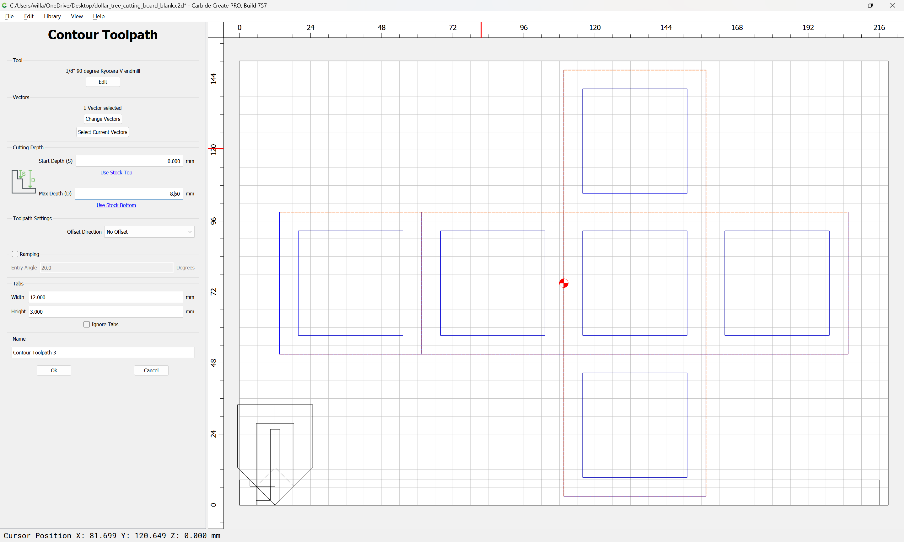
  • a small square endmill of a size which can cut completely through the stock
  • a large V endmill which can cut significantly more than half-way through the stock
  • a small/narrow V endmill which can be used to cut the V in-between the finger joints and the edges of the part

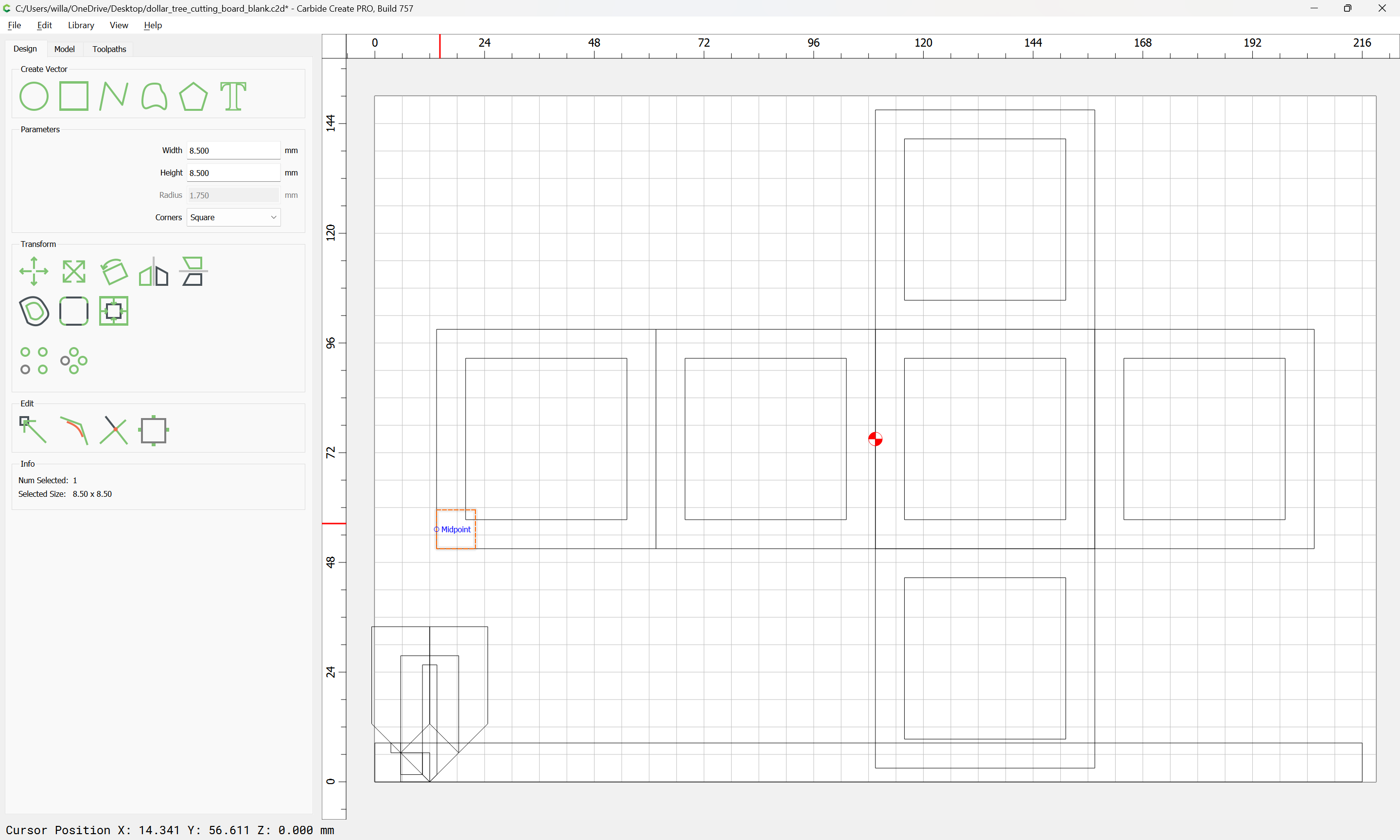
Start by drawing things up in profile:

(stock thickness is 8.5mm)

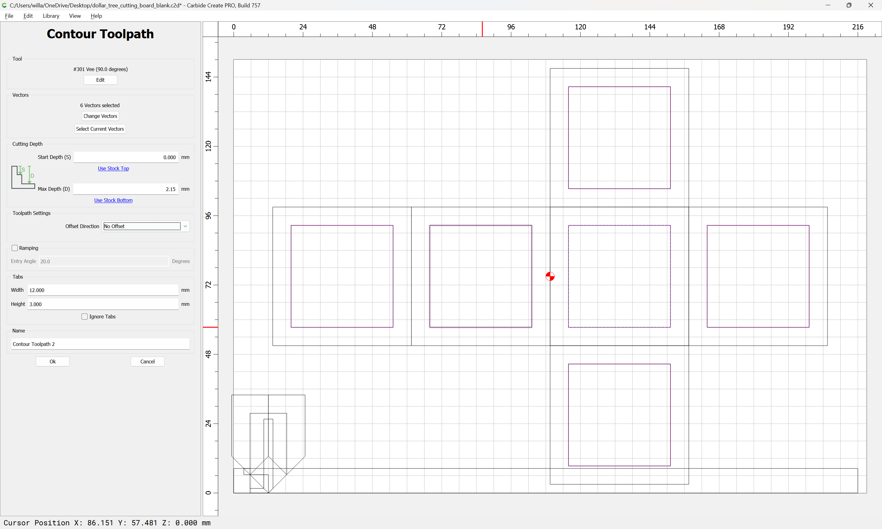
The larger tool is a #301 (or 301e for Essential):

(which has a cutting diameter of 1/2")

Though a tool such as:

might simplify things even further or perhaps yield a better result, but I don’t know if it’s $131.04 better.

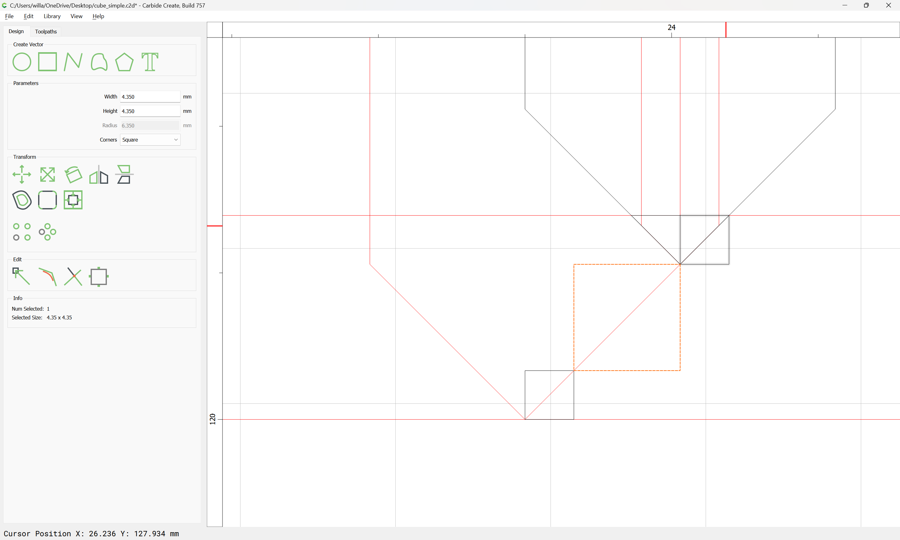
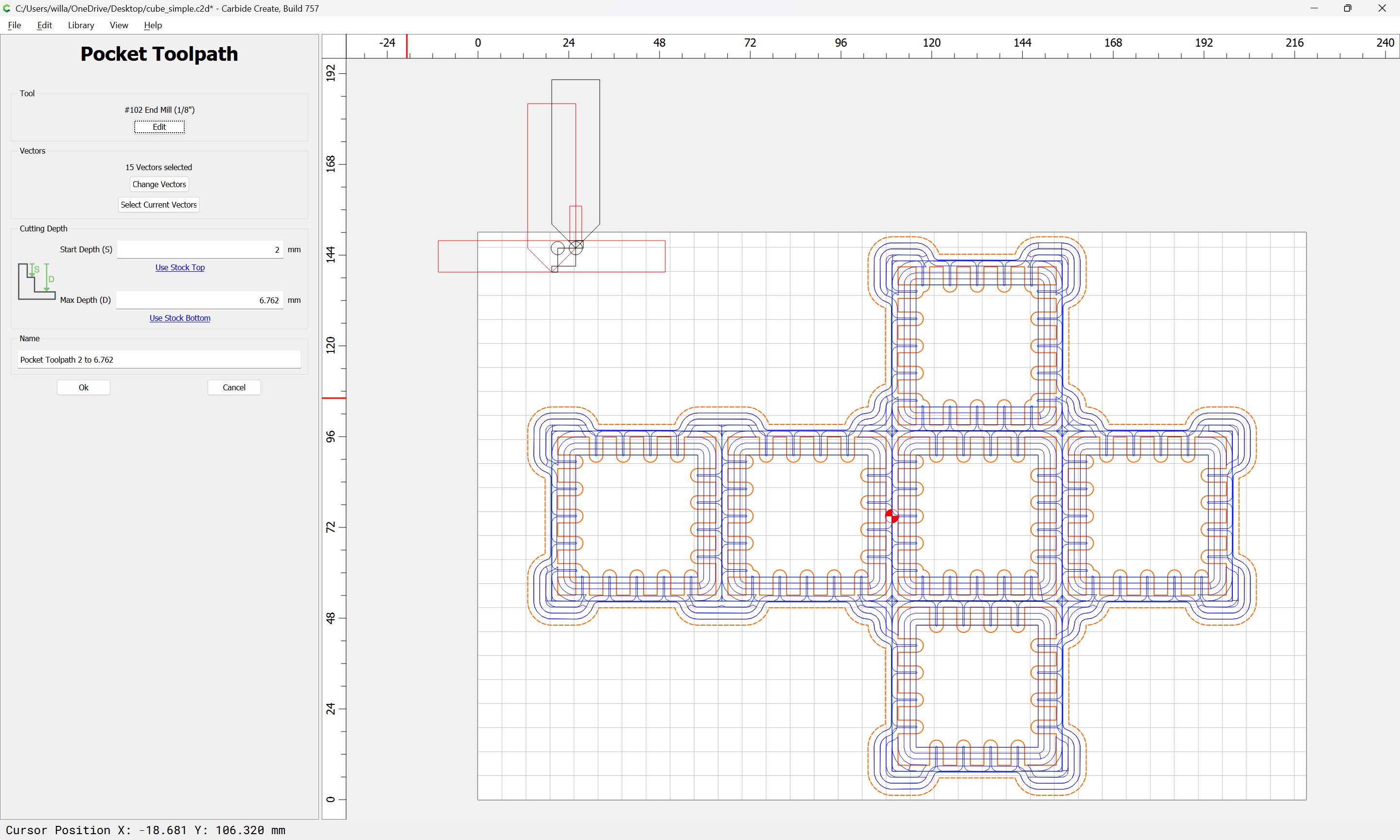
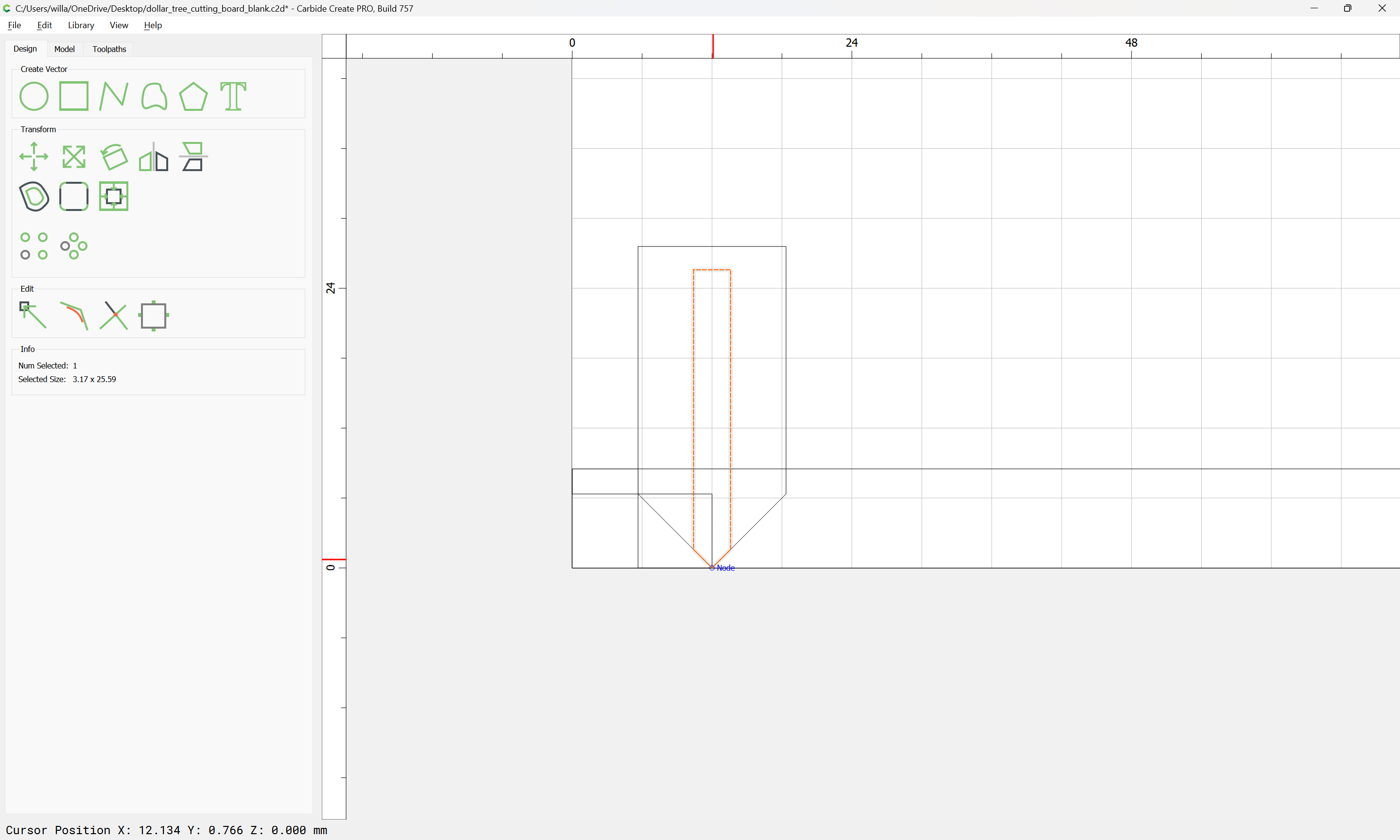
Zooming in after arranging the profile of the tool we see that we will need to cut

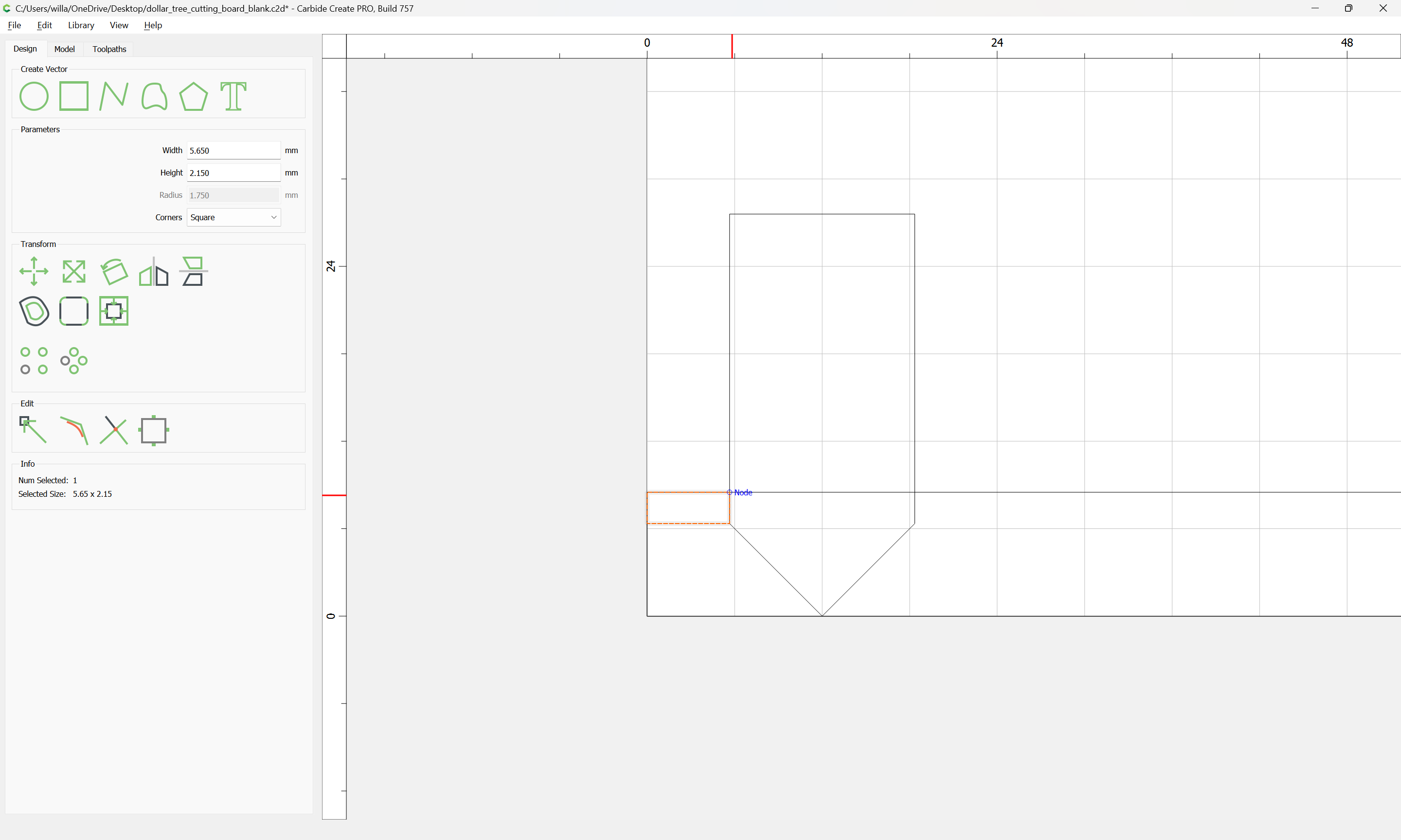
2.15mm deep to meet up with where the V endmill stops cutting the miter.

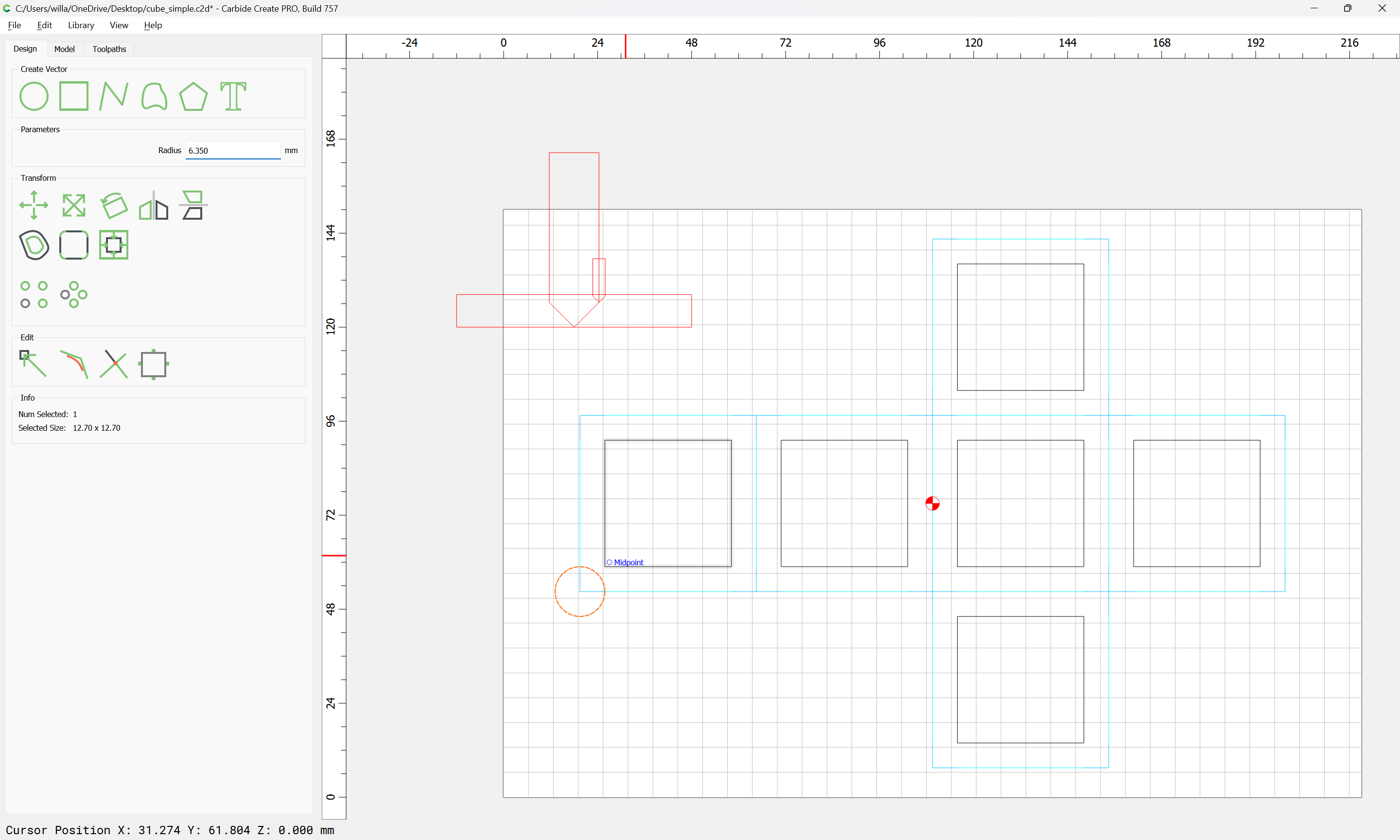
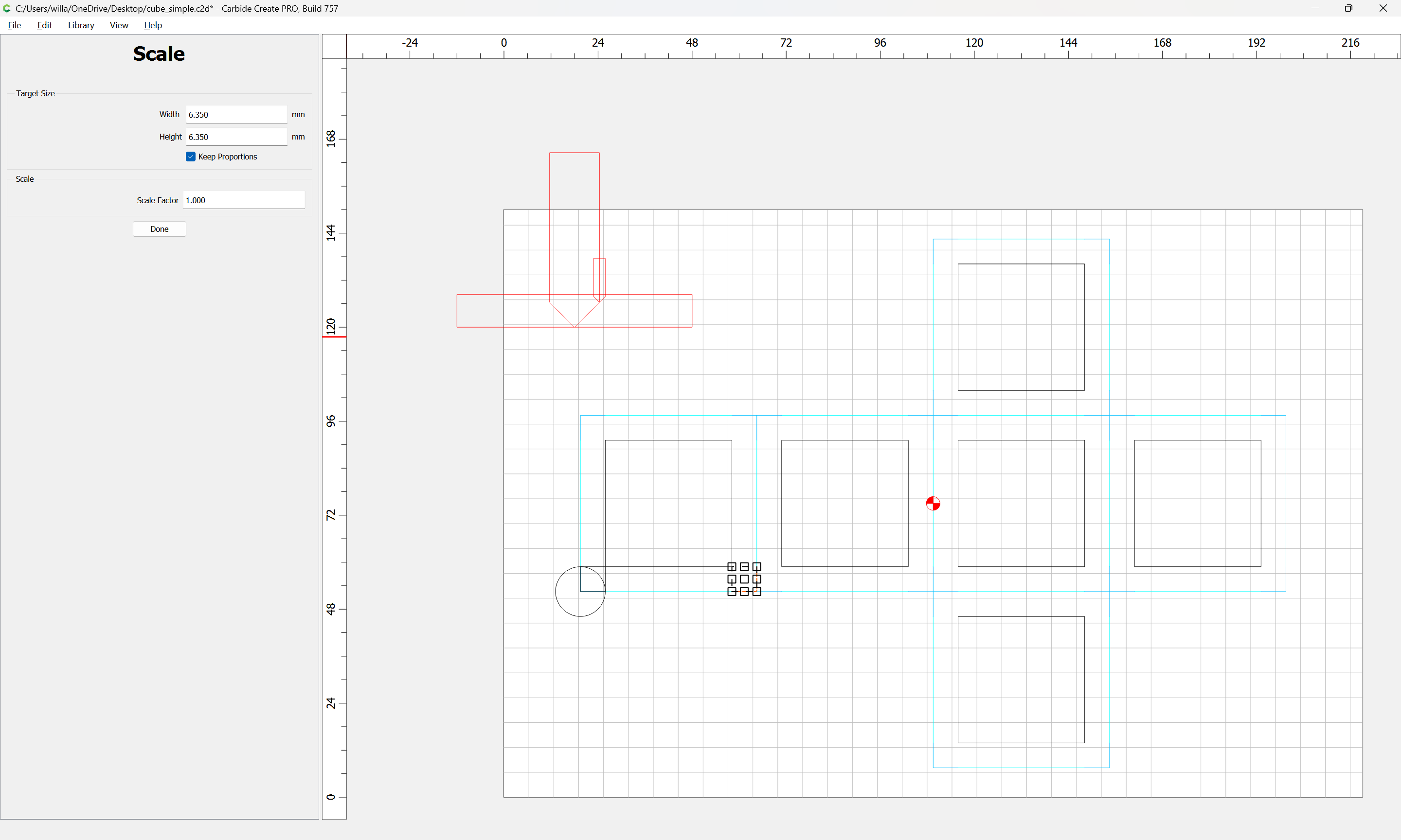
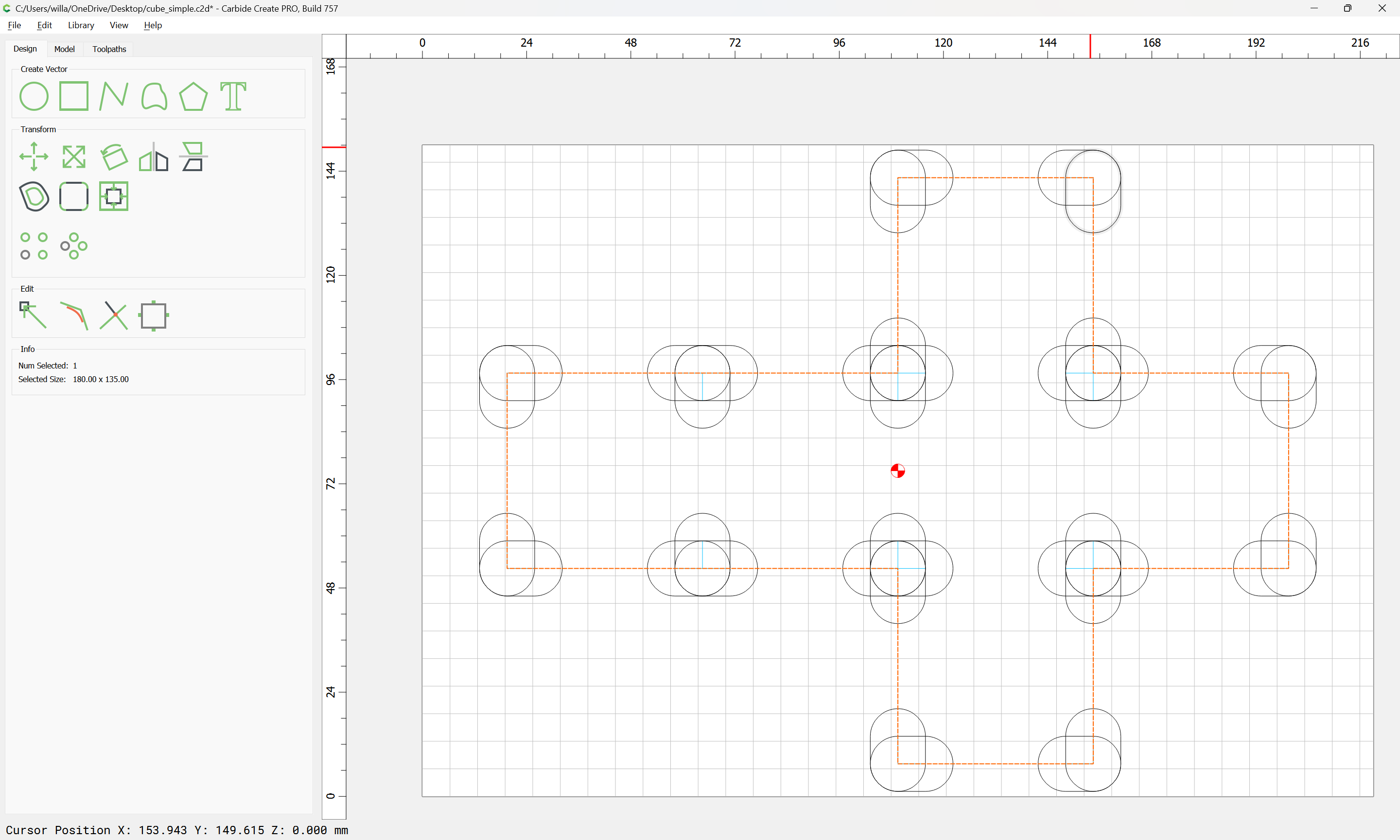
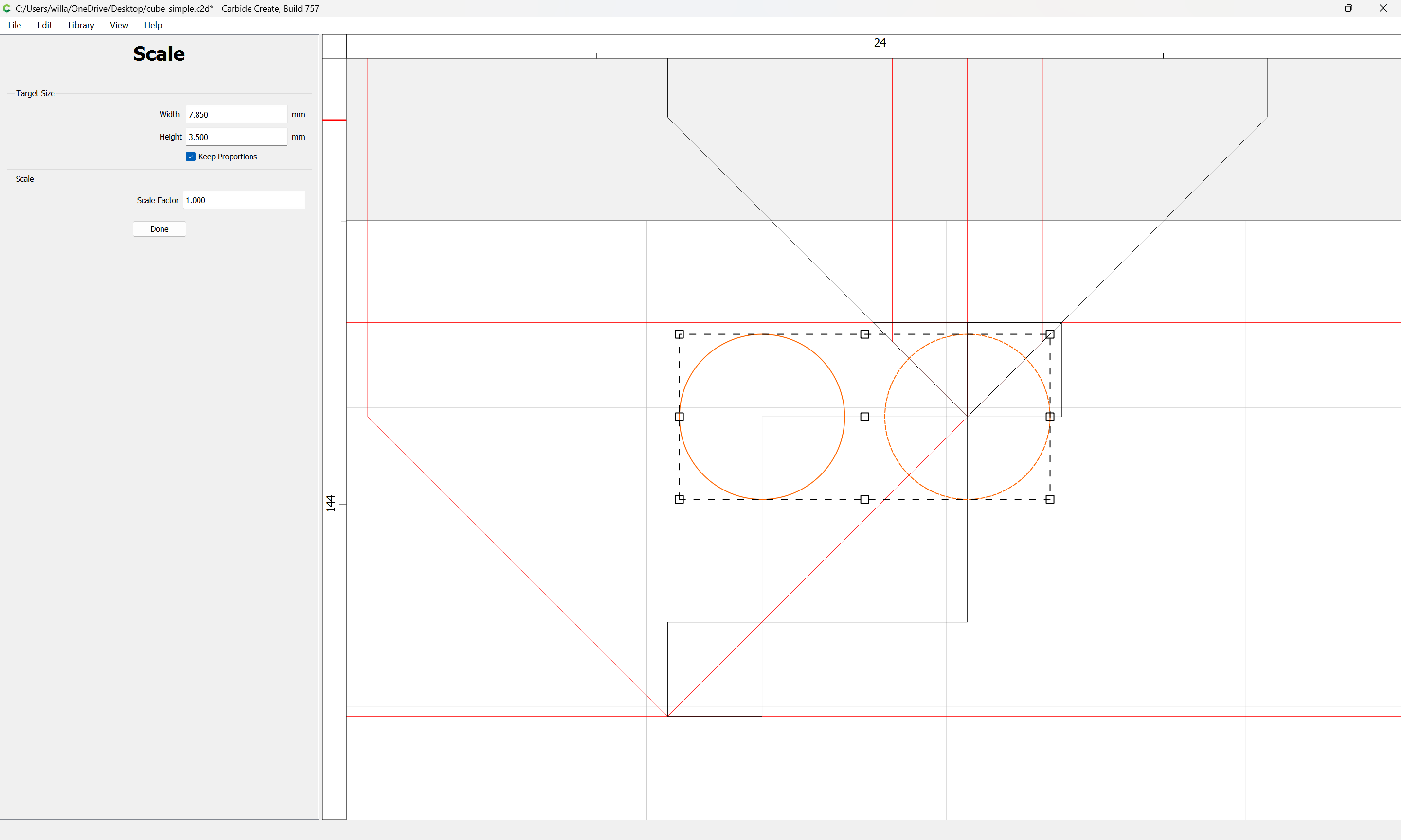
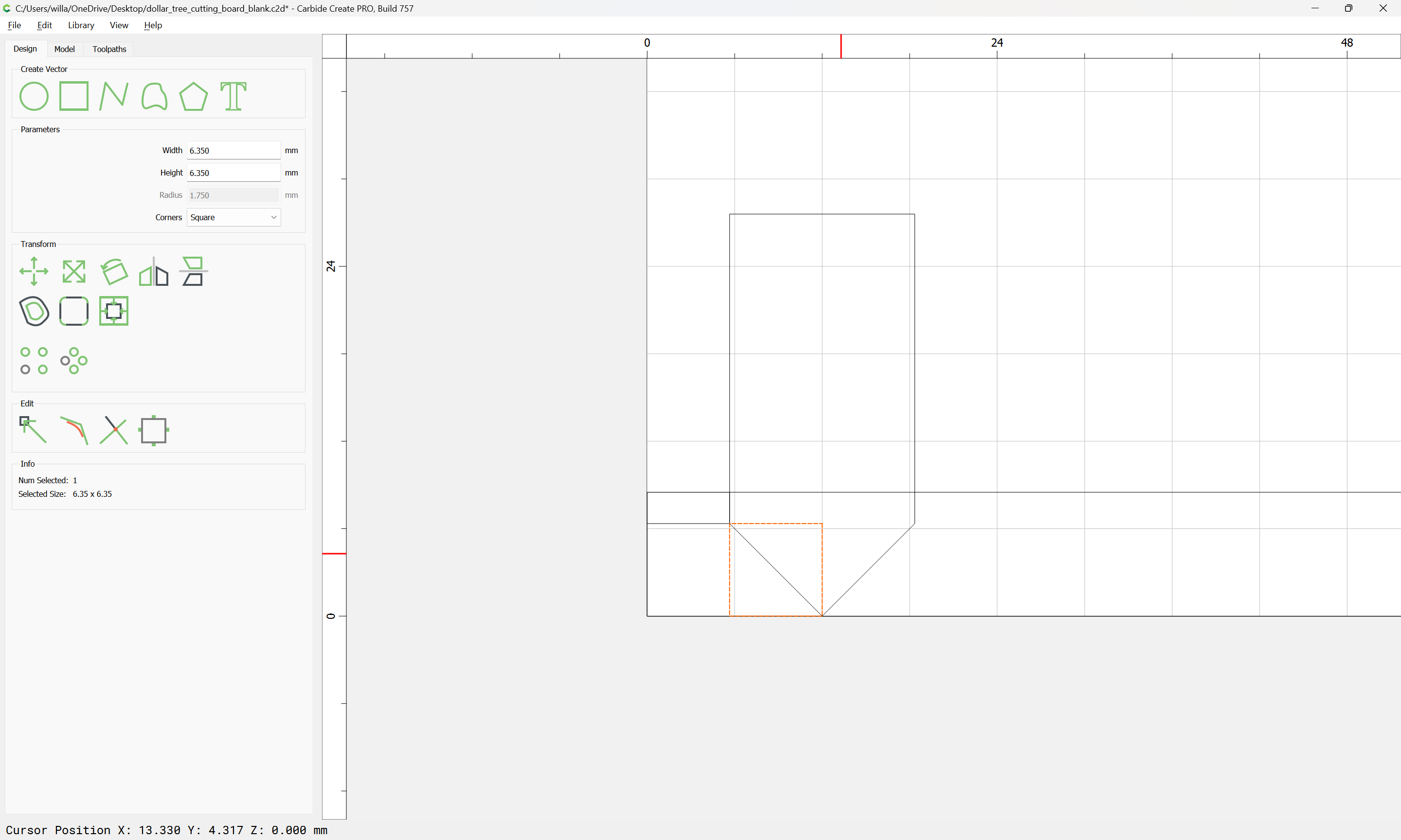
Measuring the tool we get half its diameter as the distance where that will be inset:

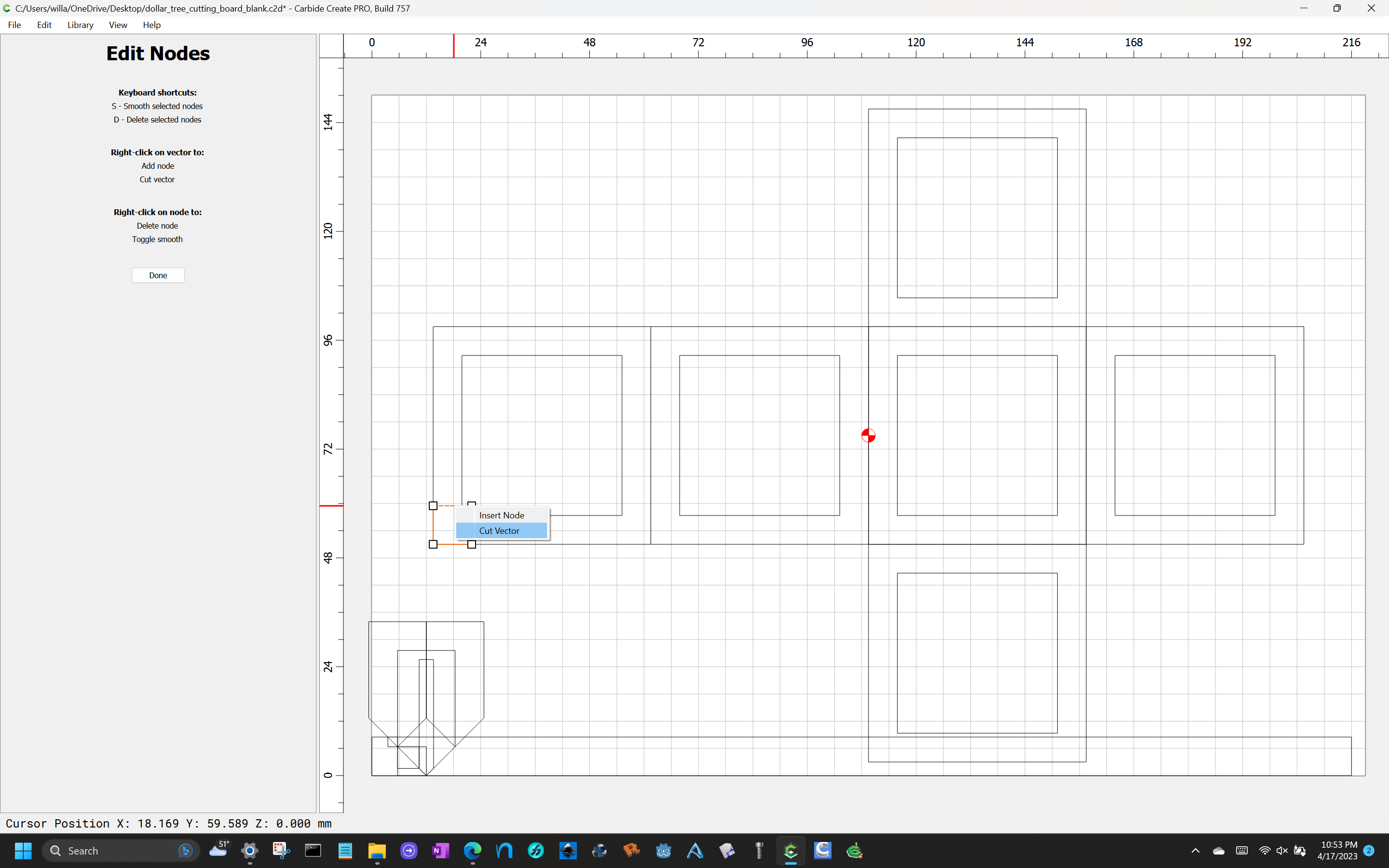
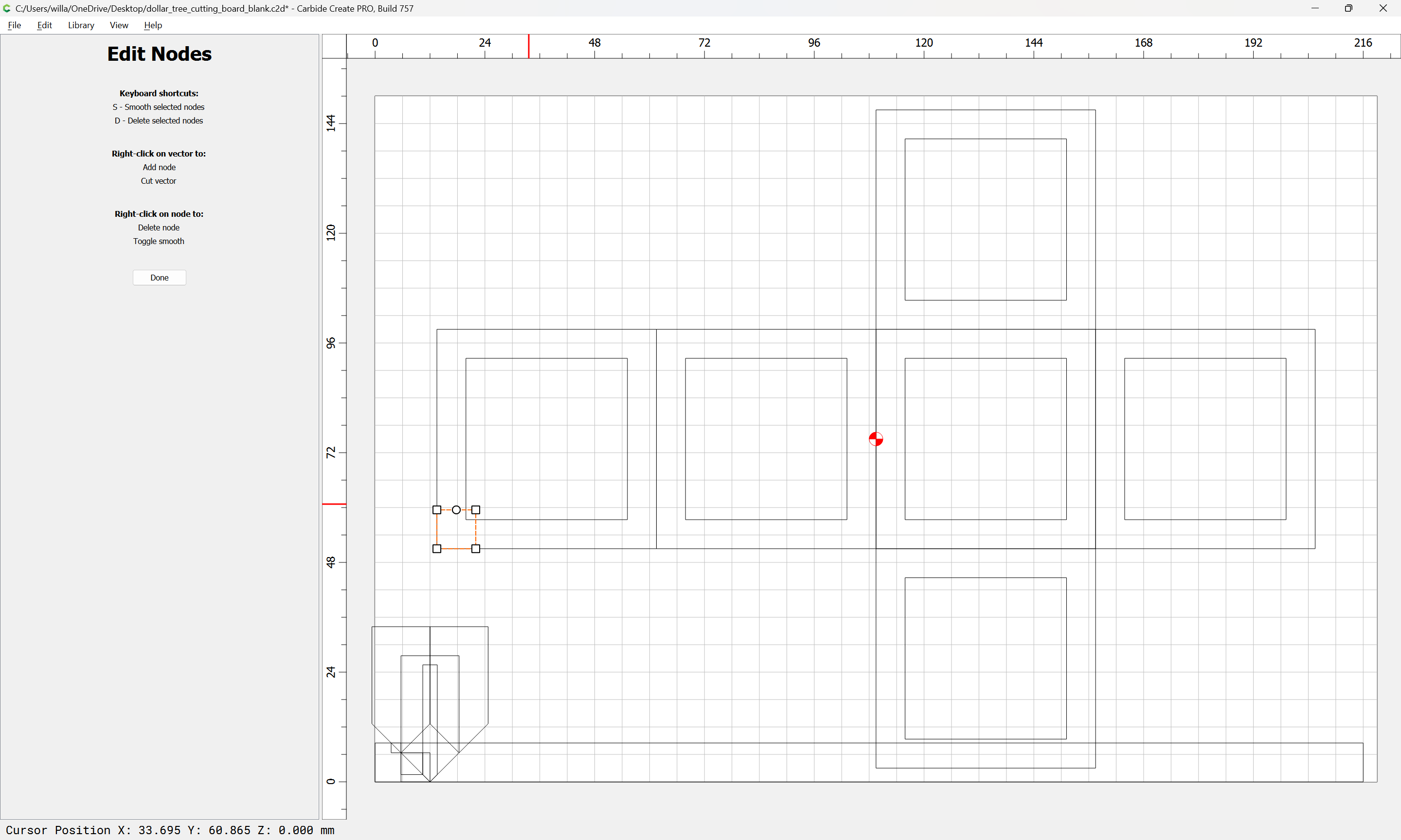
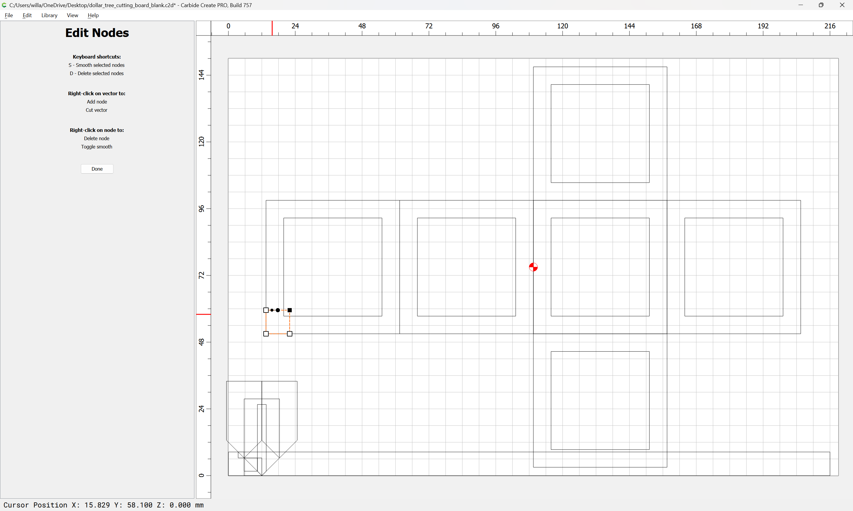
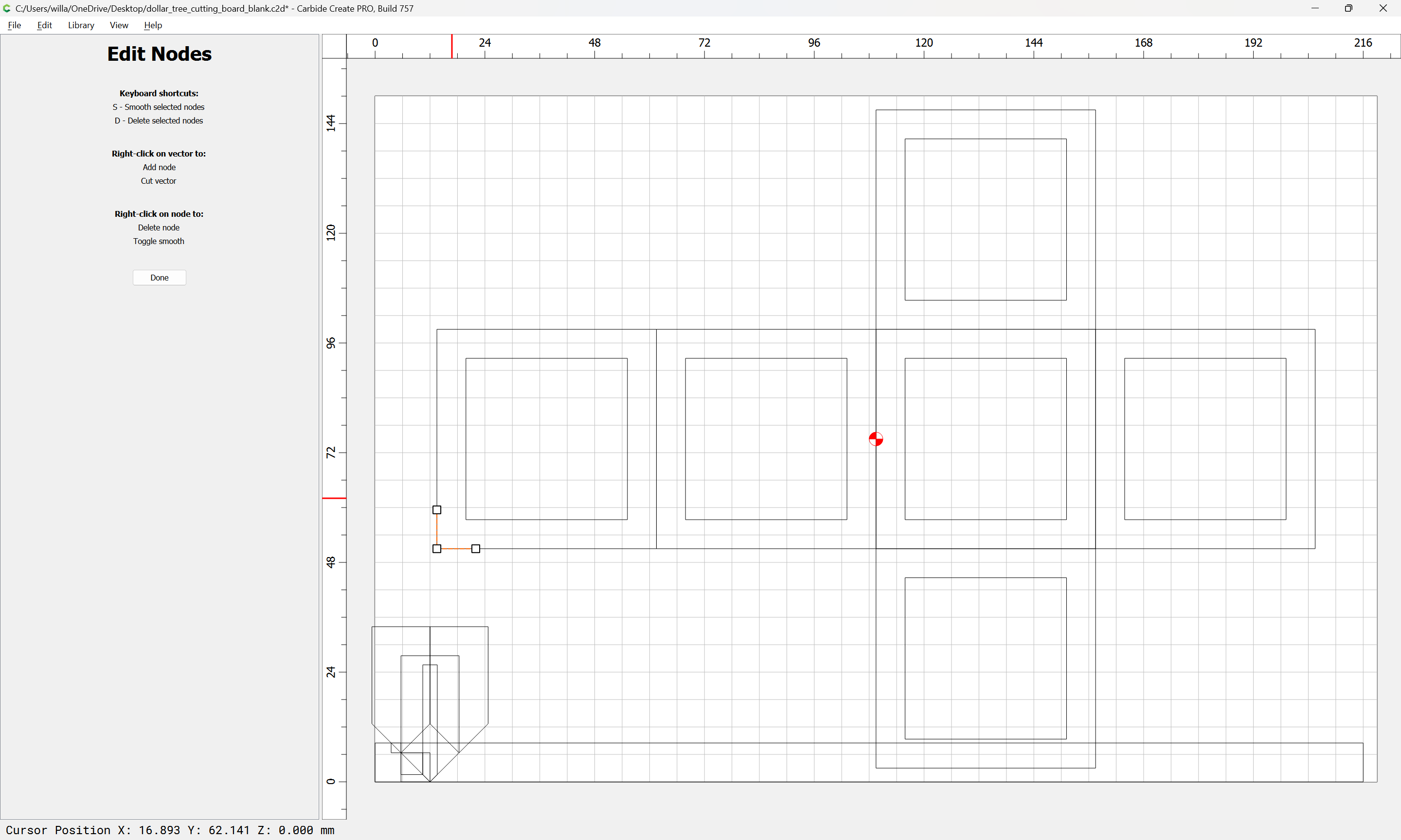
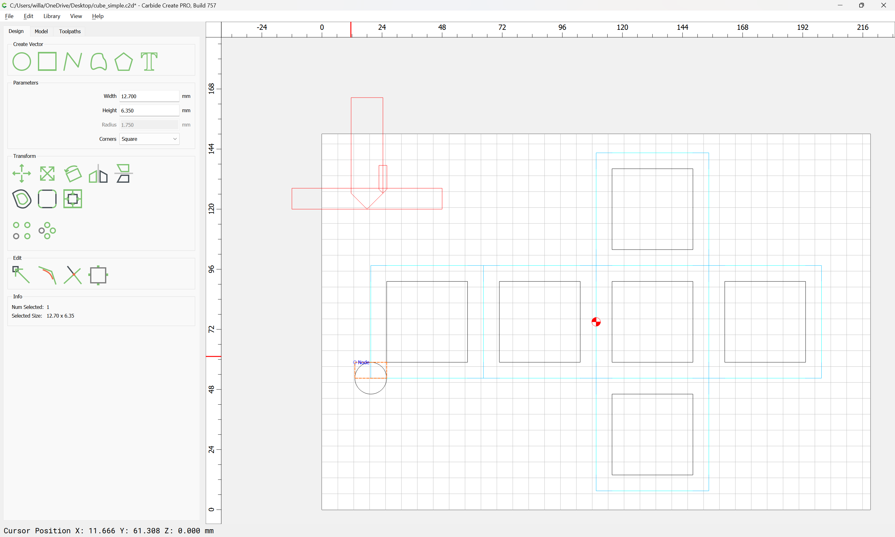
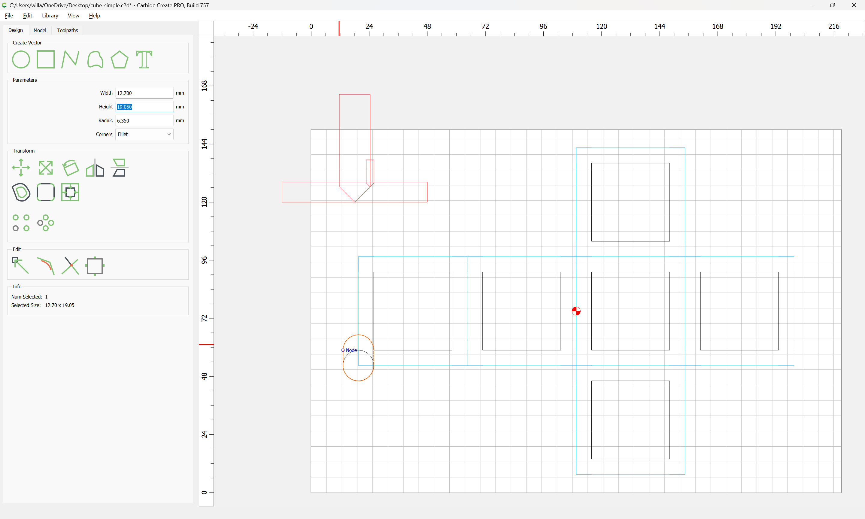
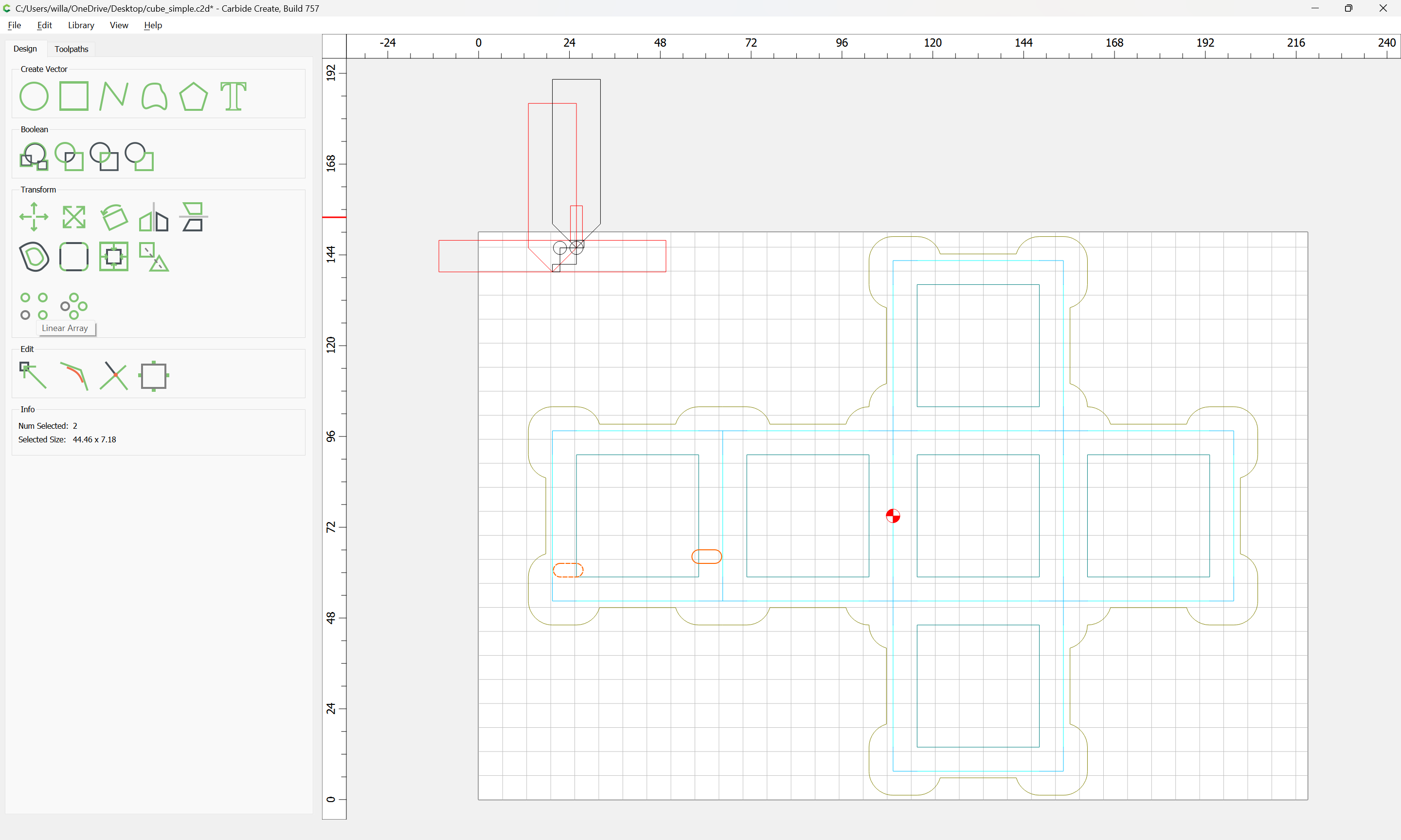
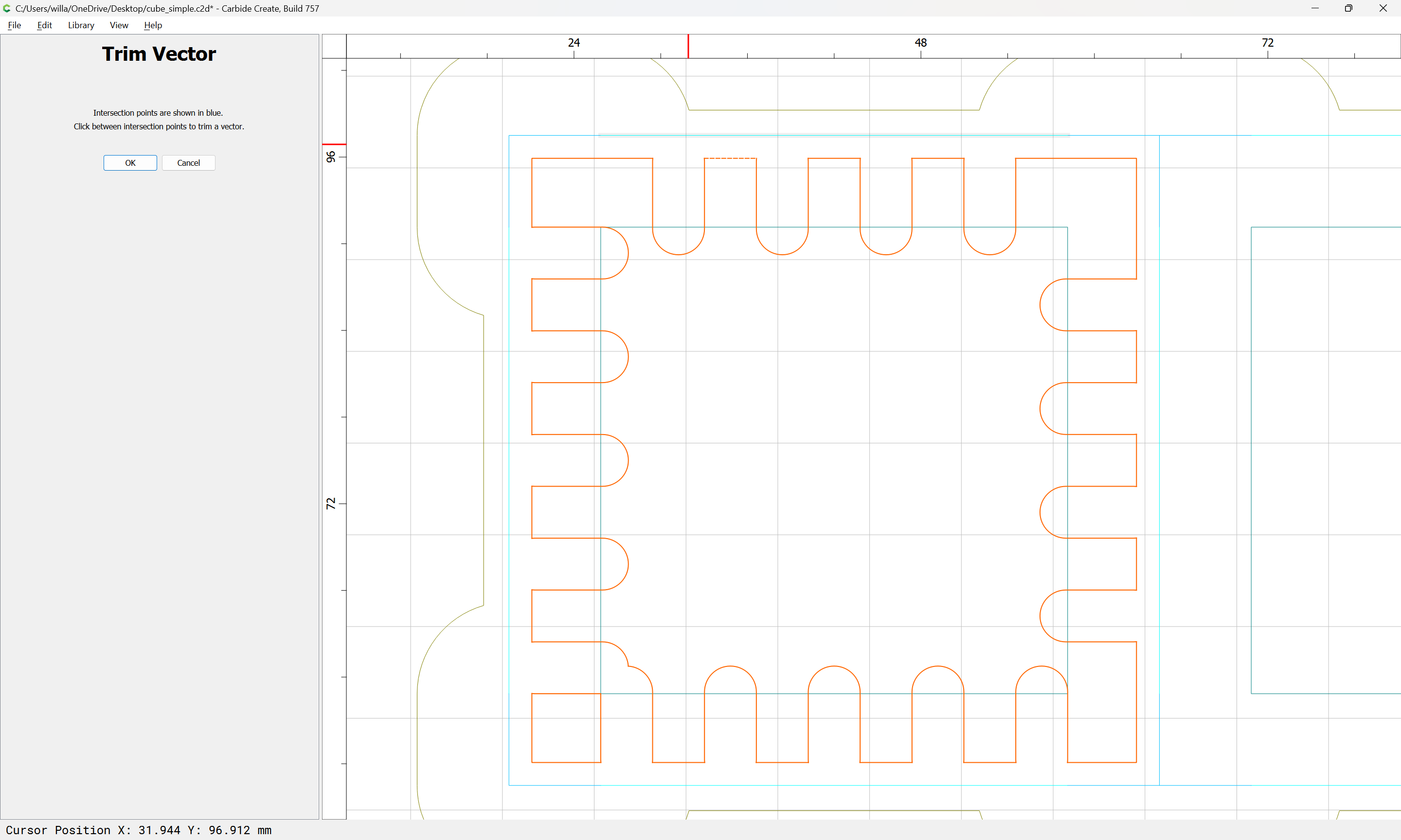
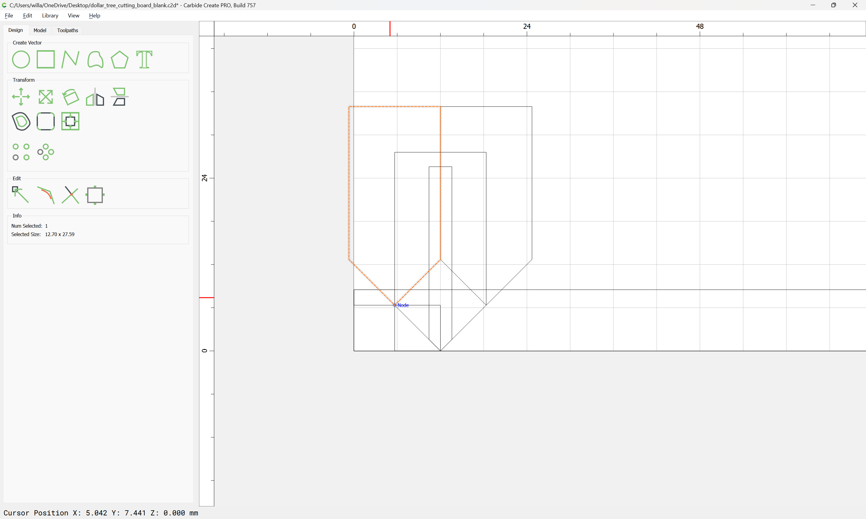
So we arrange things to show this and the other necessary geometry — the central cut with the smaller V tool:

The cuts at the top of the finger joinery:

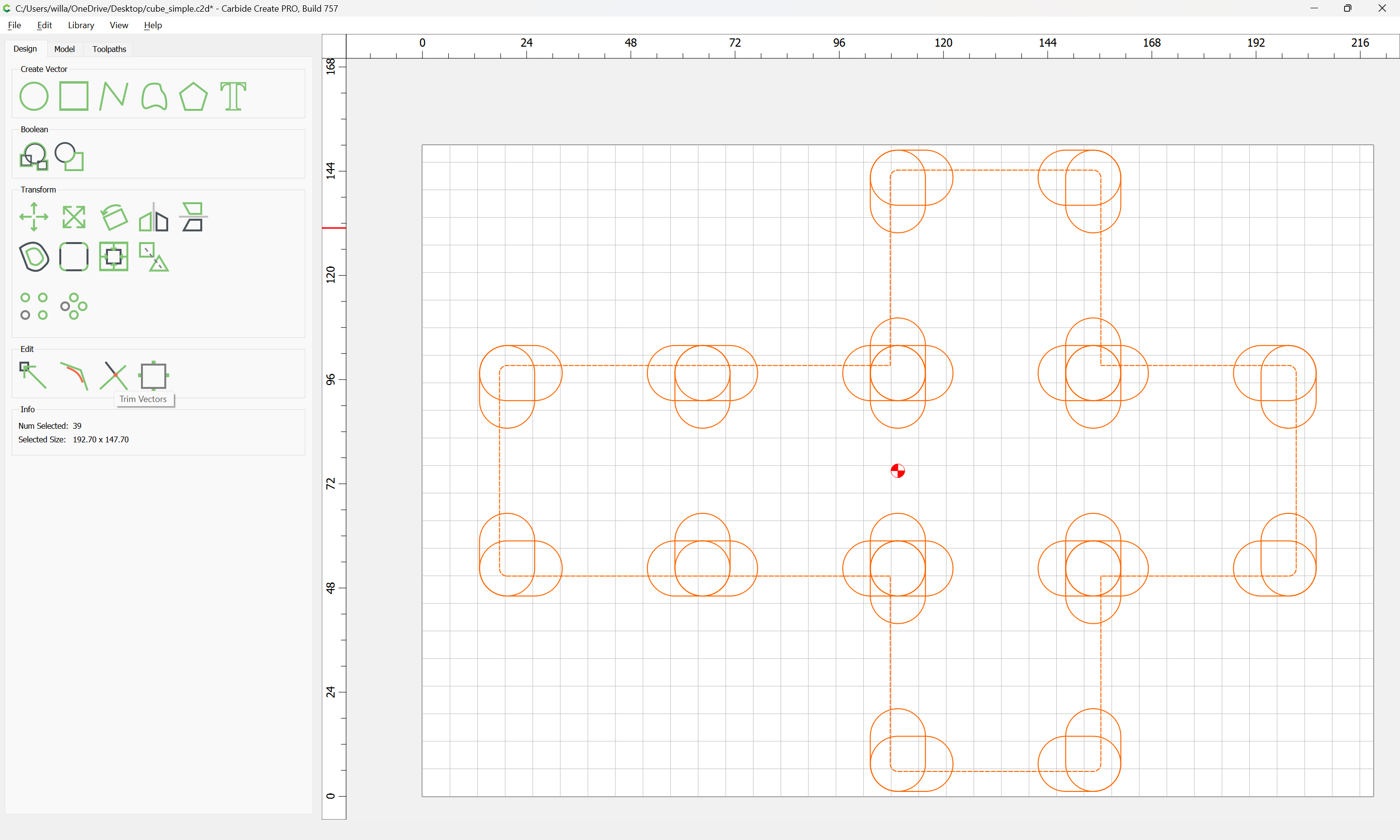
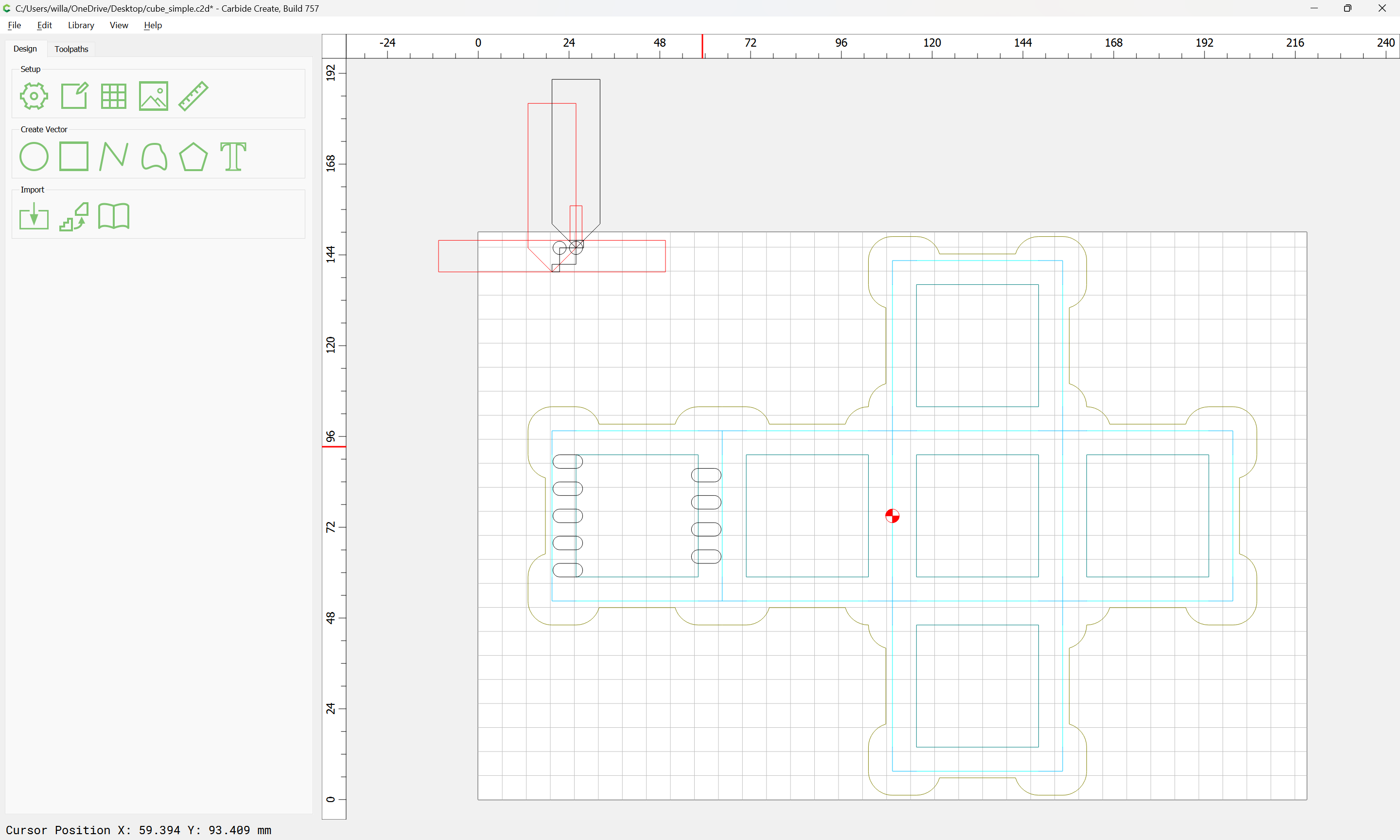
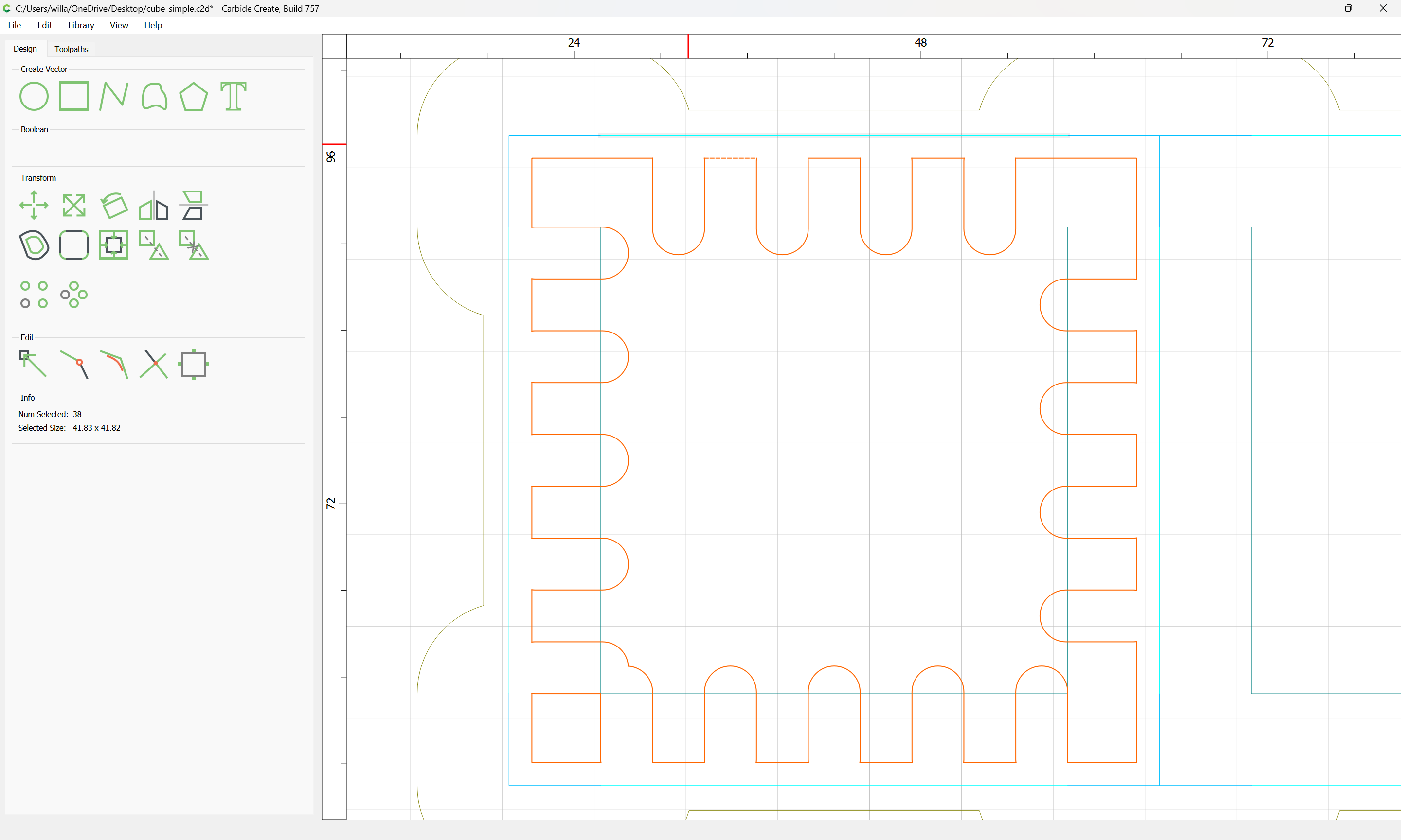
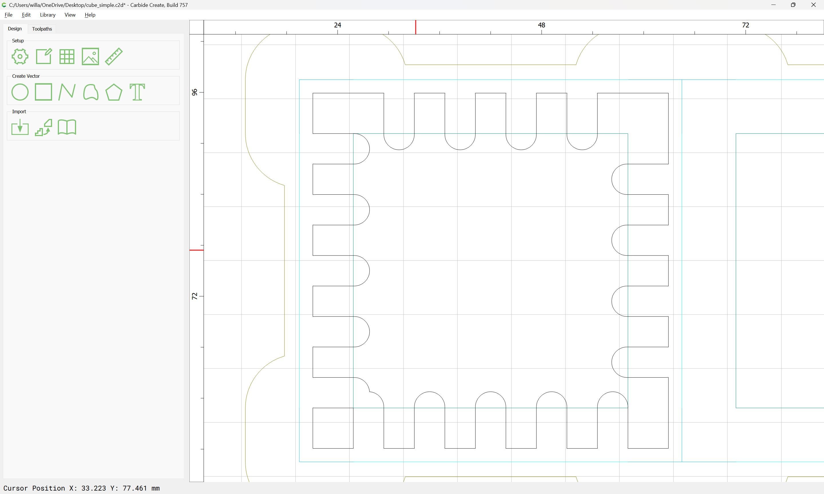
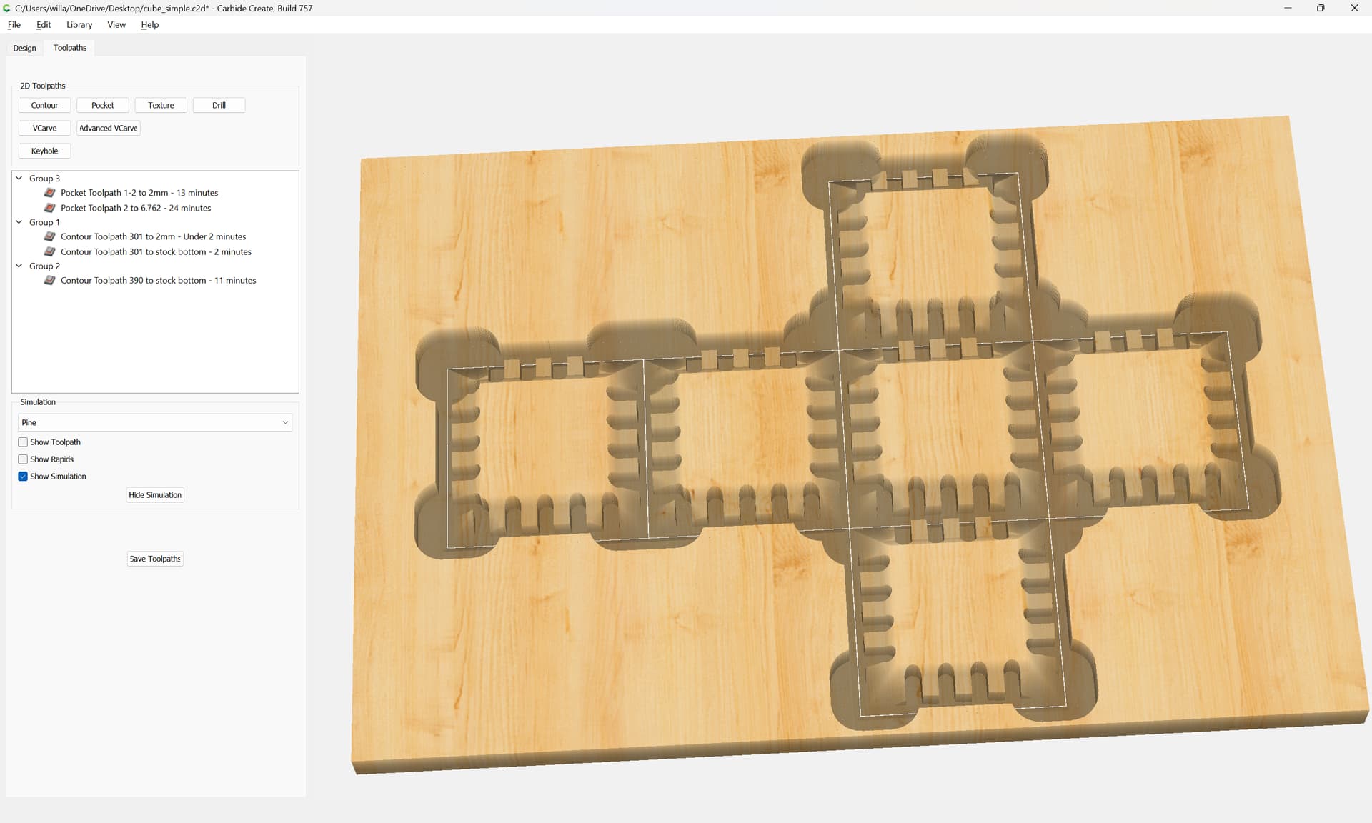
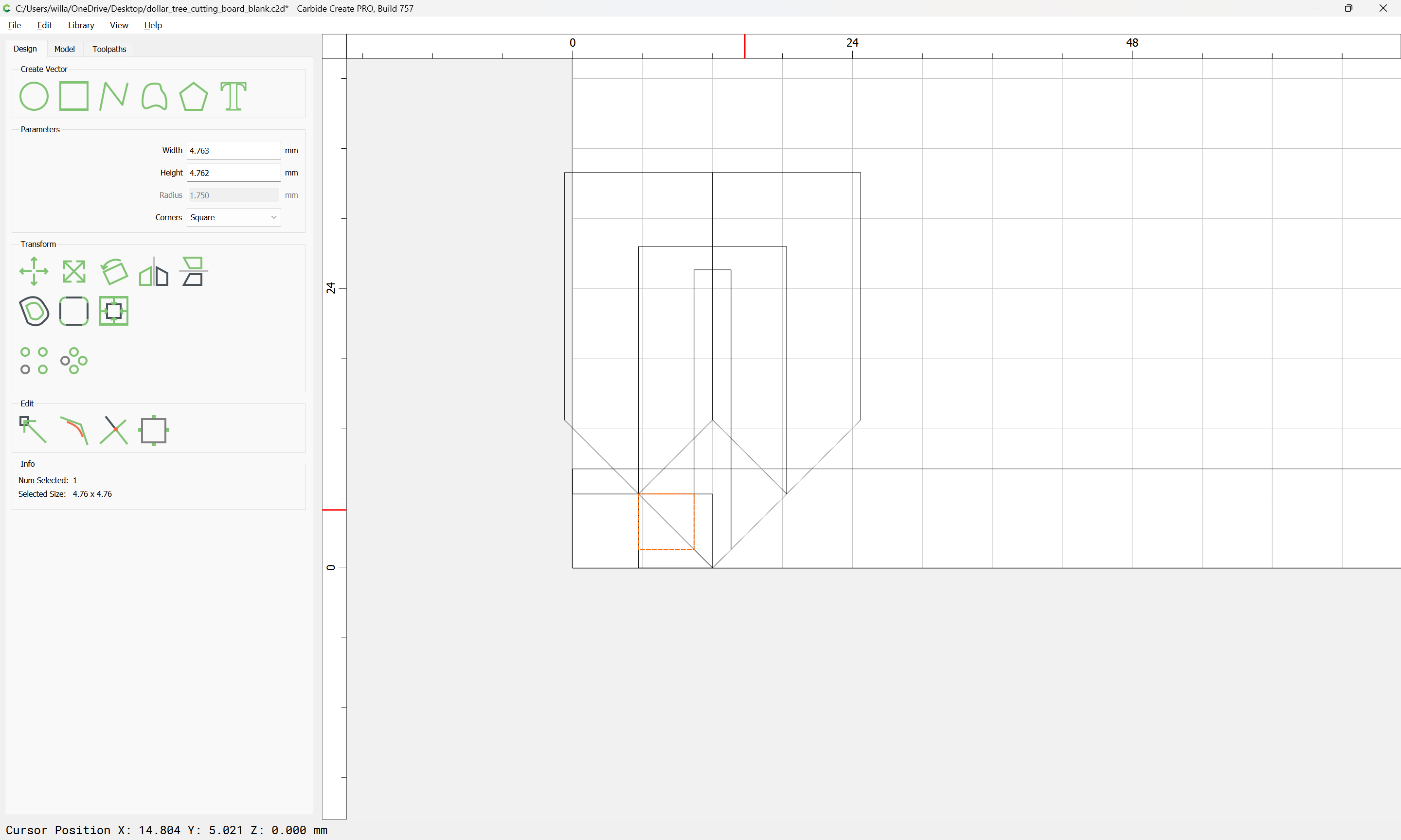
The geometry of the finger joinery:

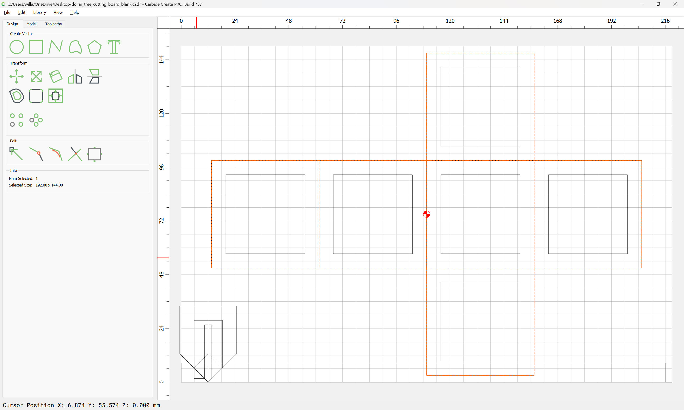
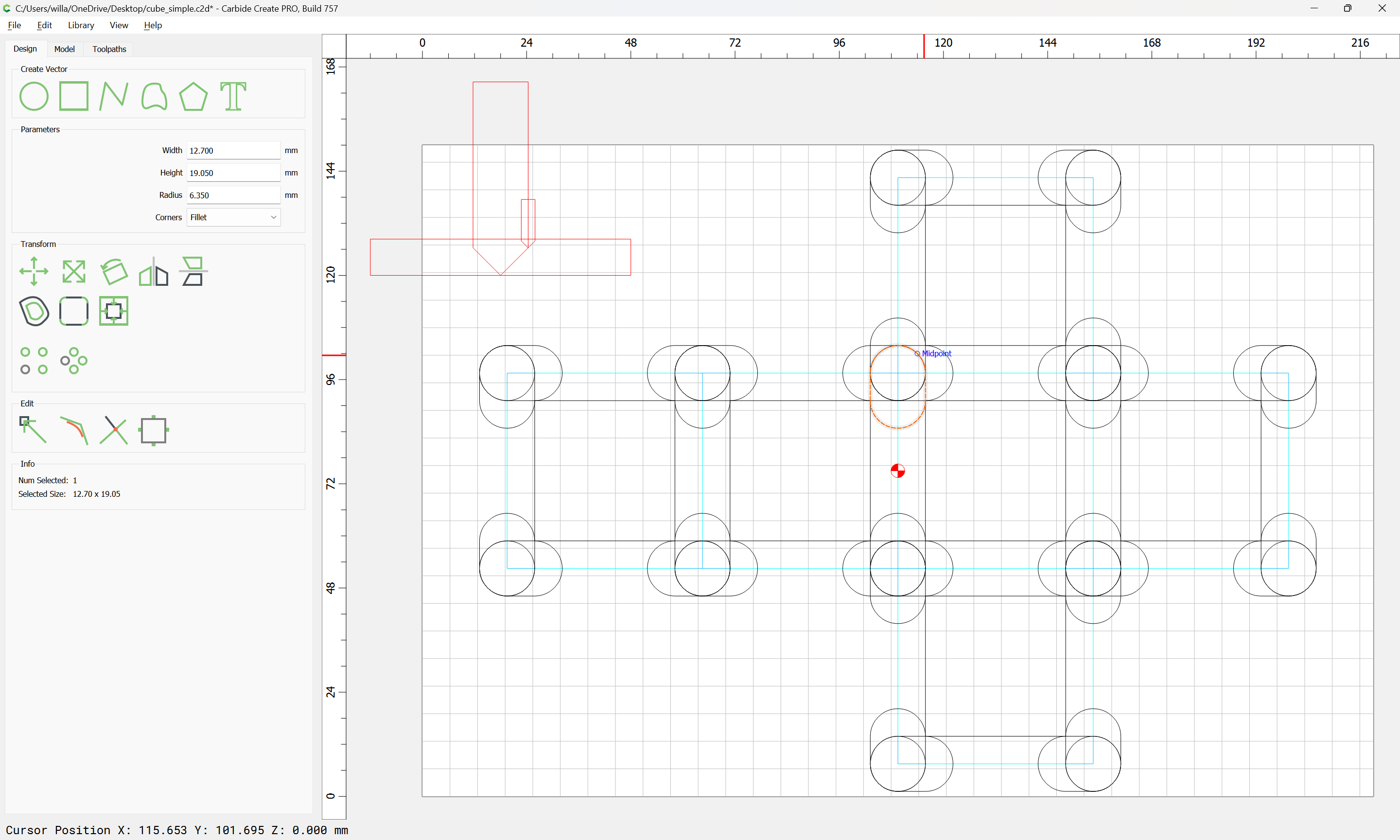
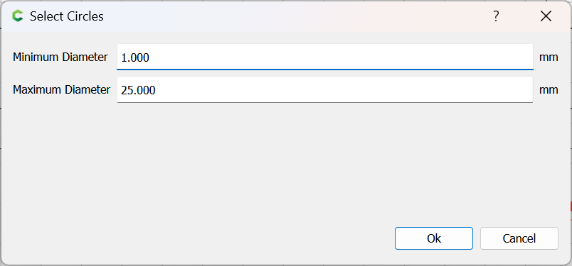
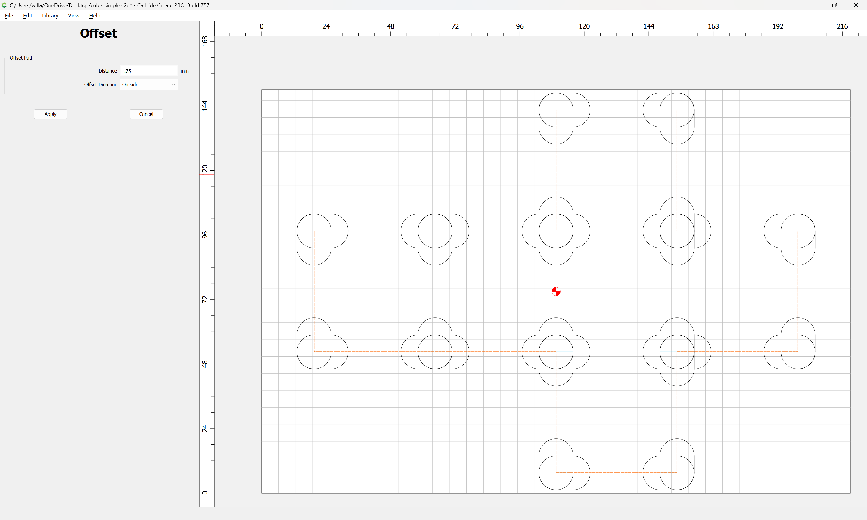
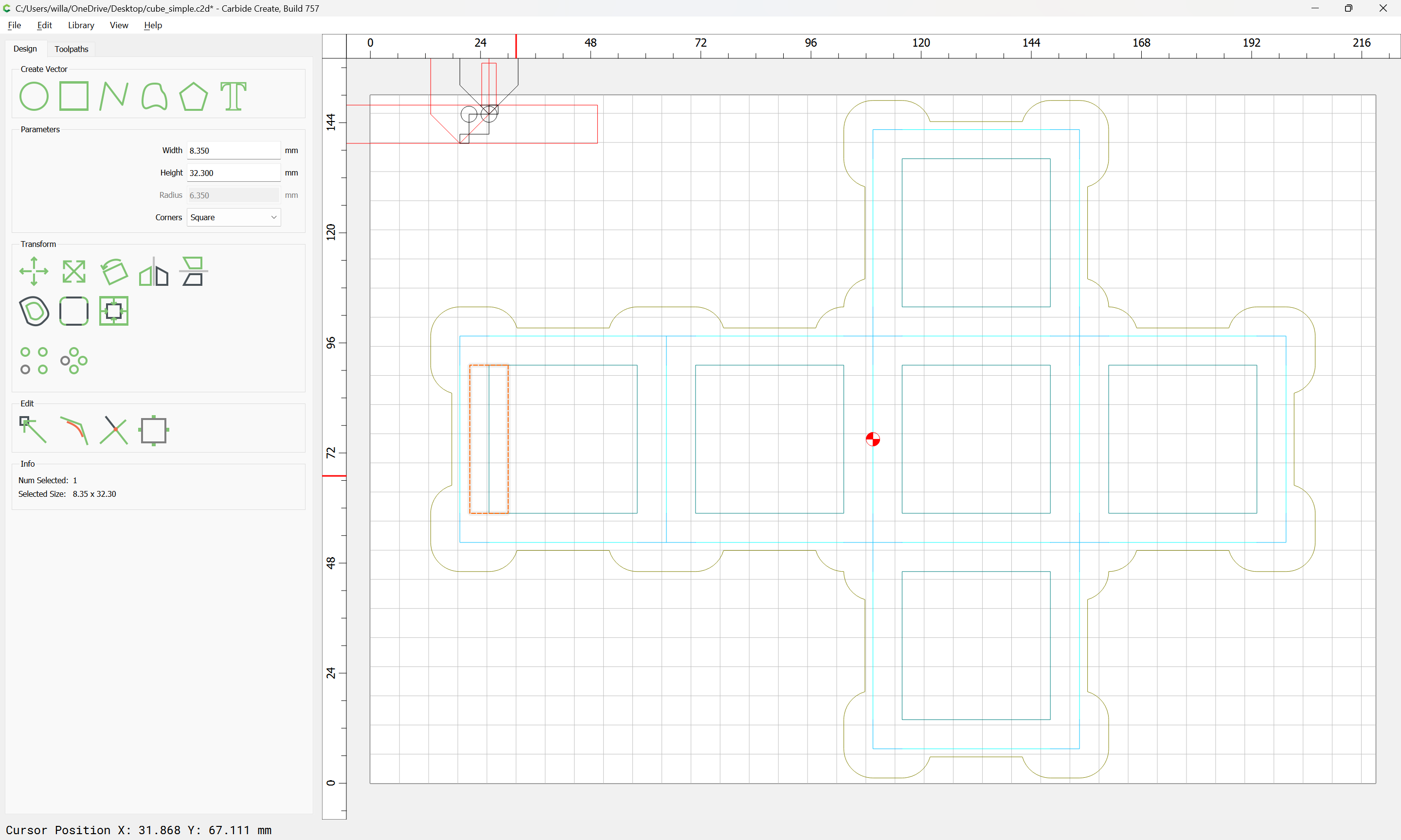
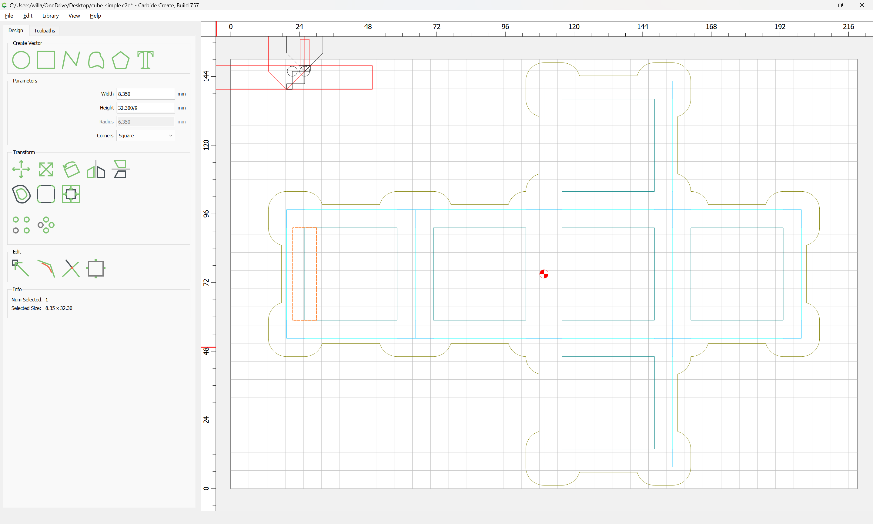
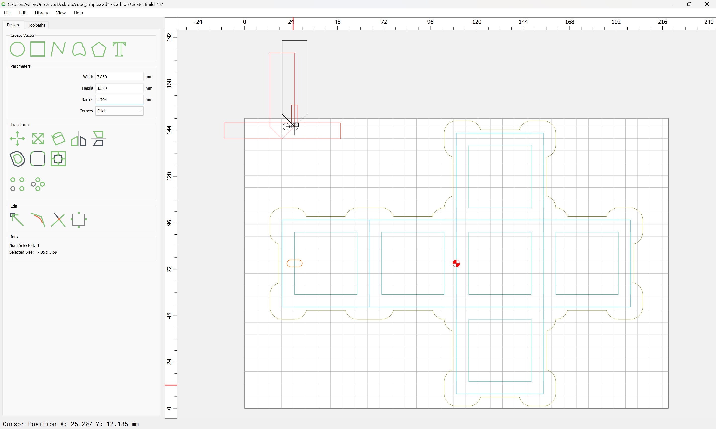
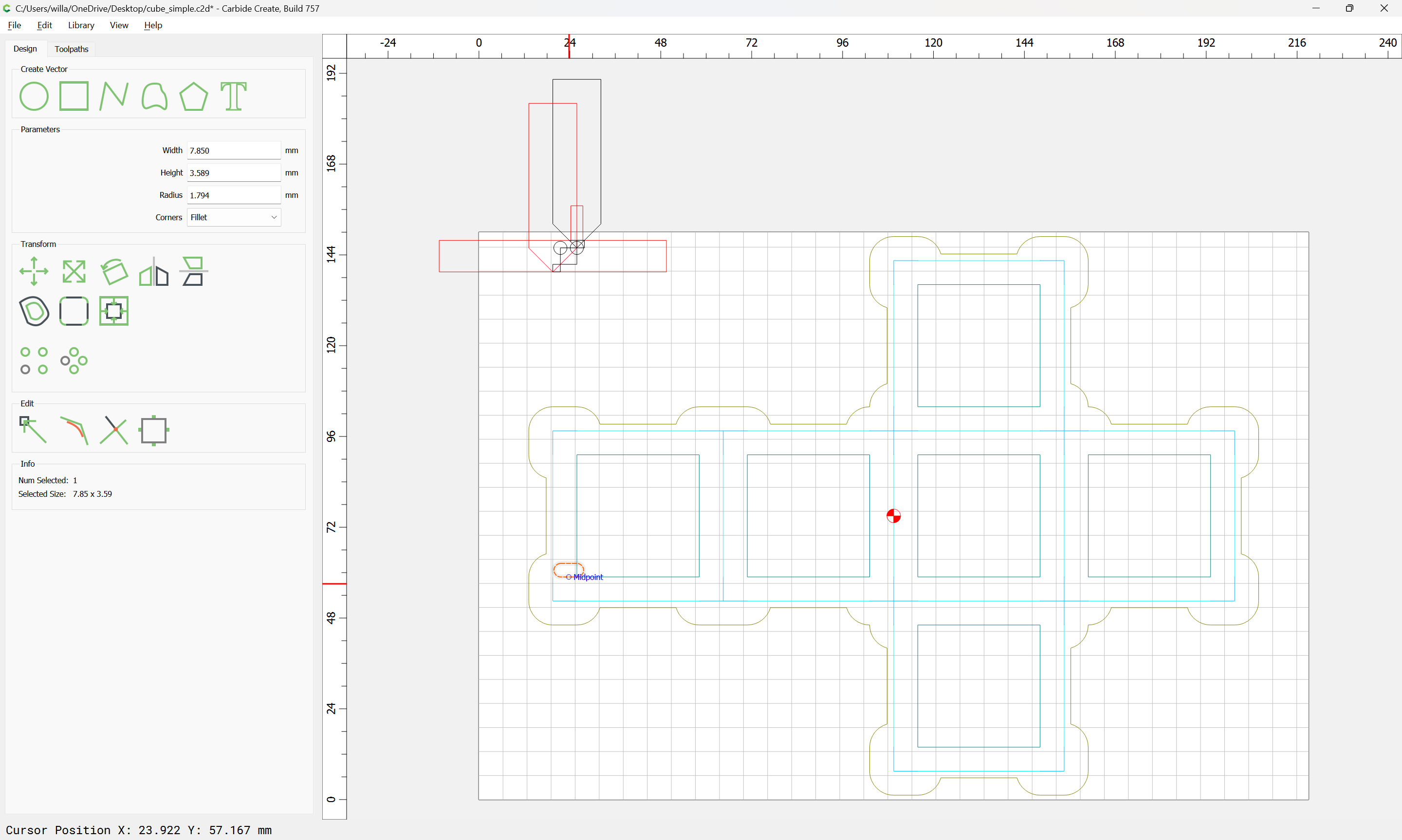
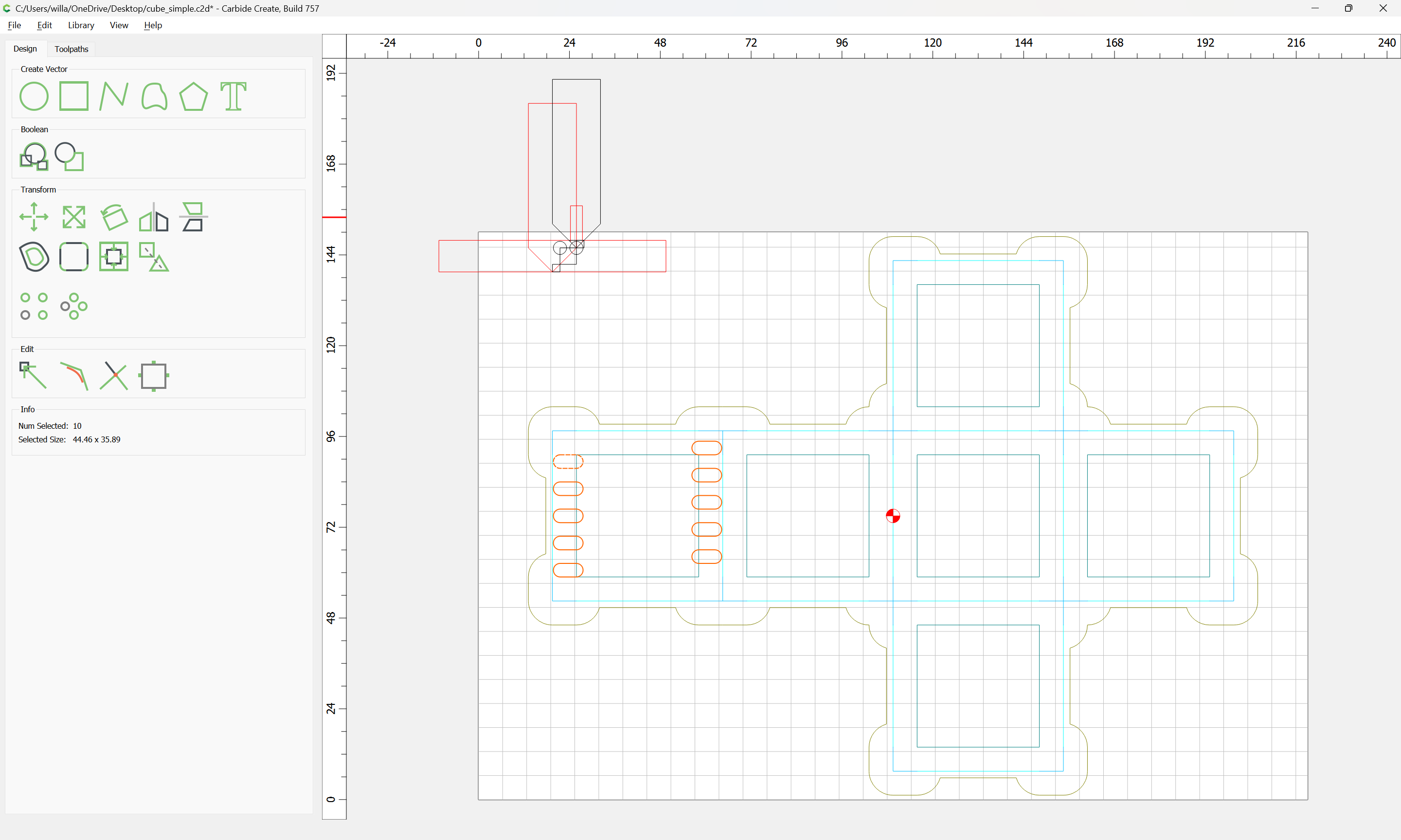
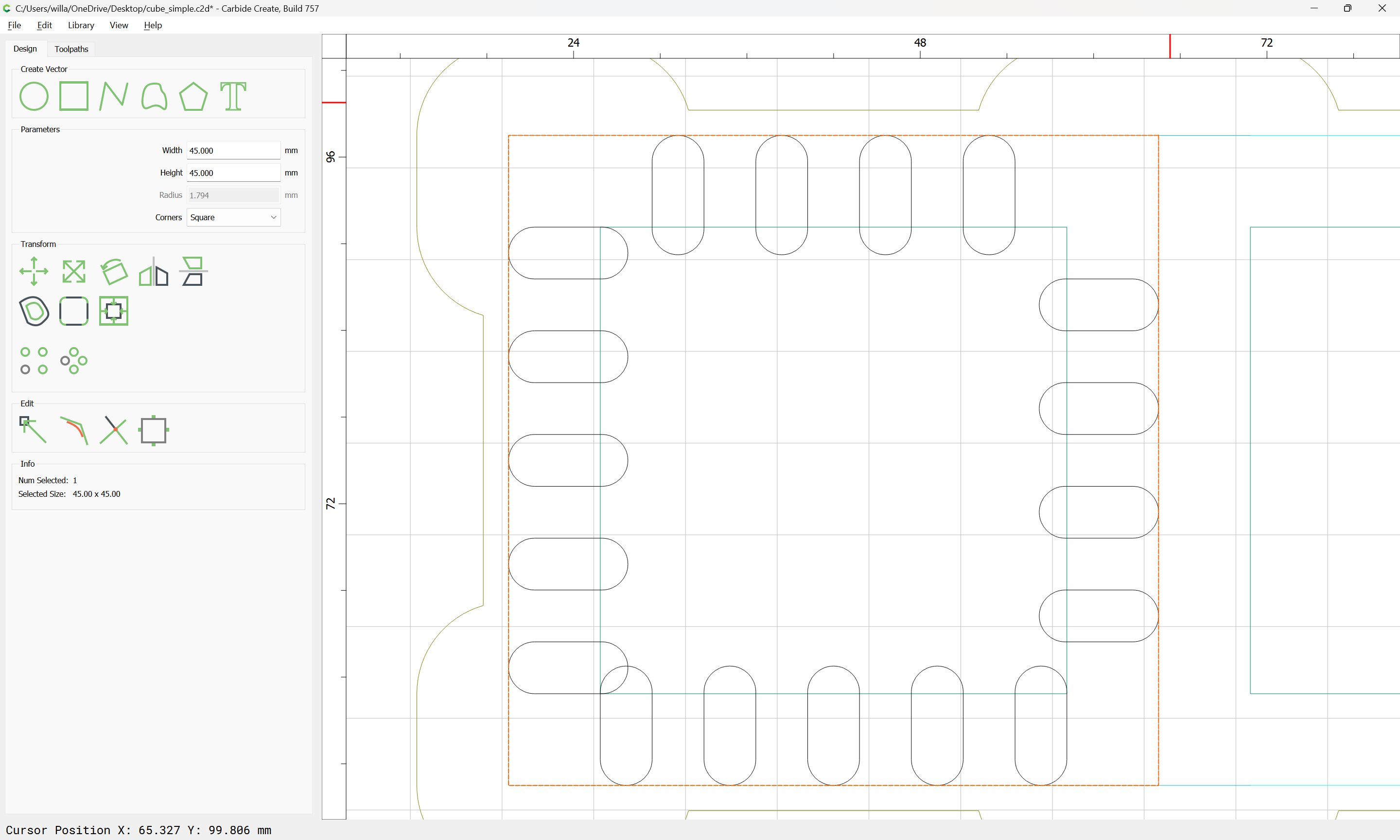
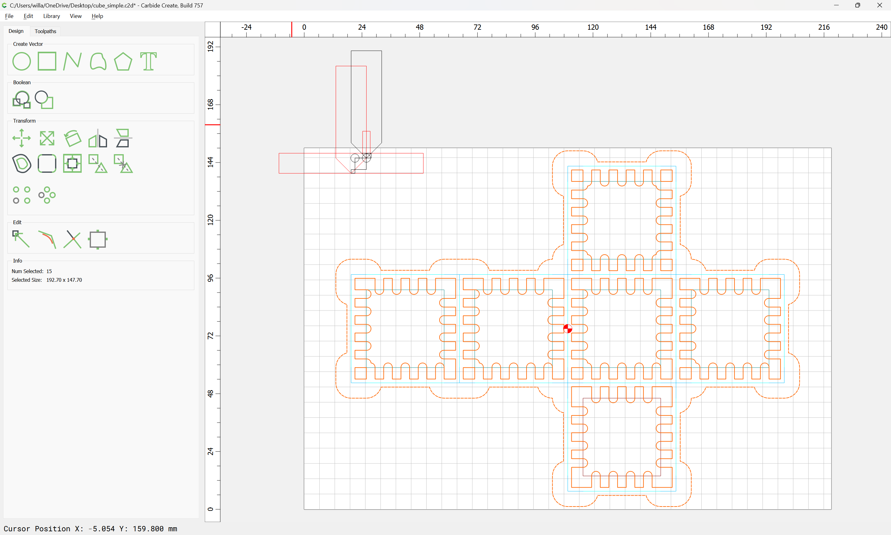
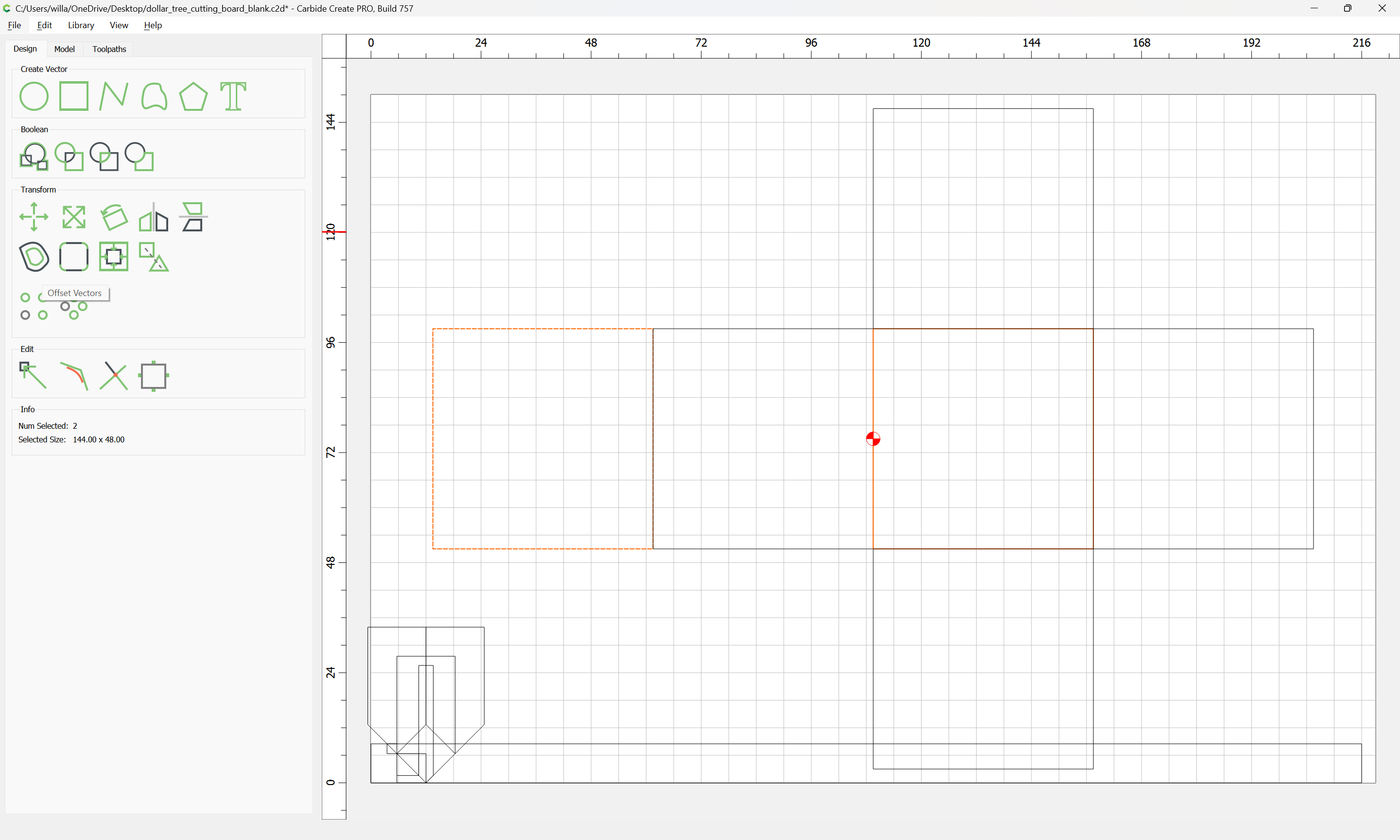
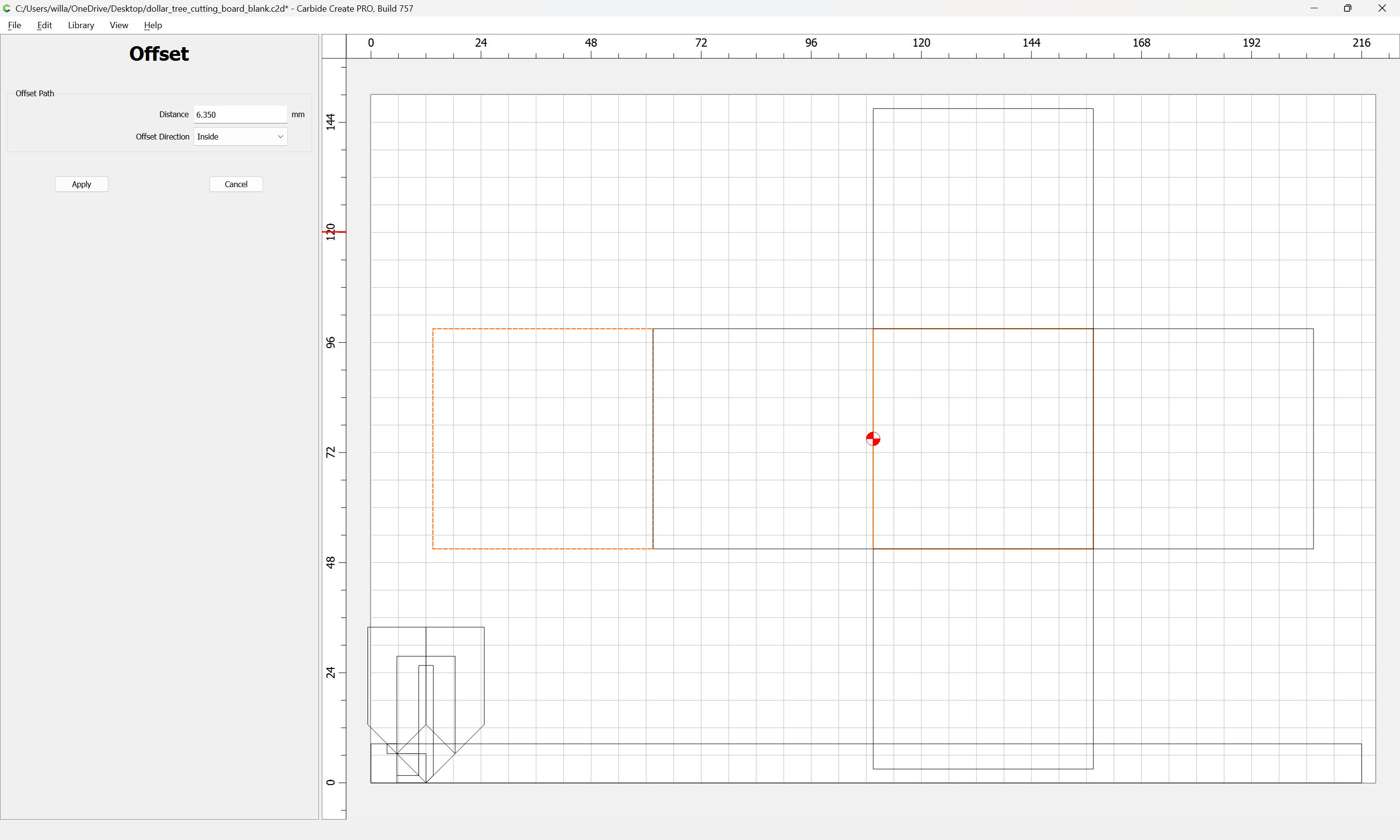
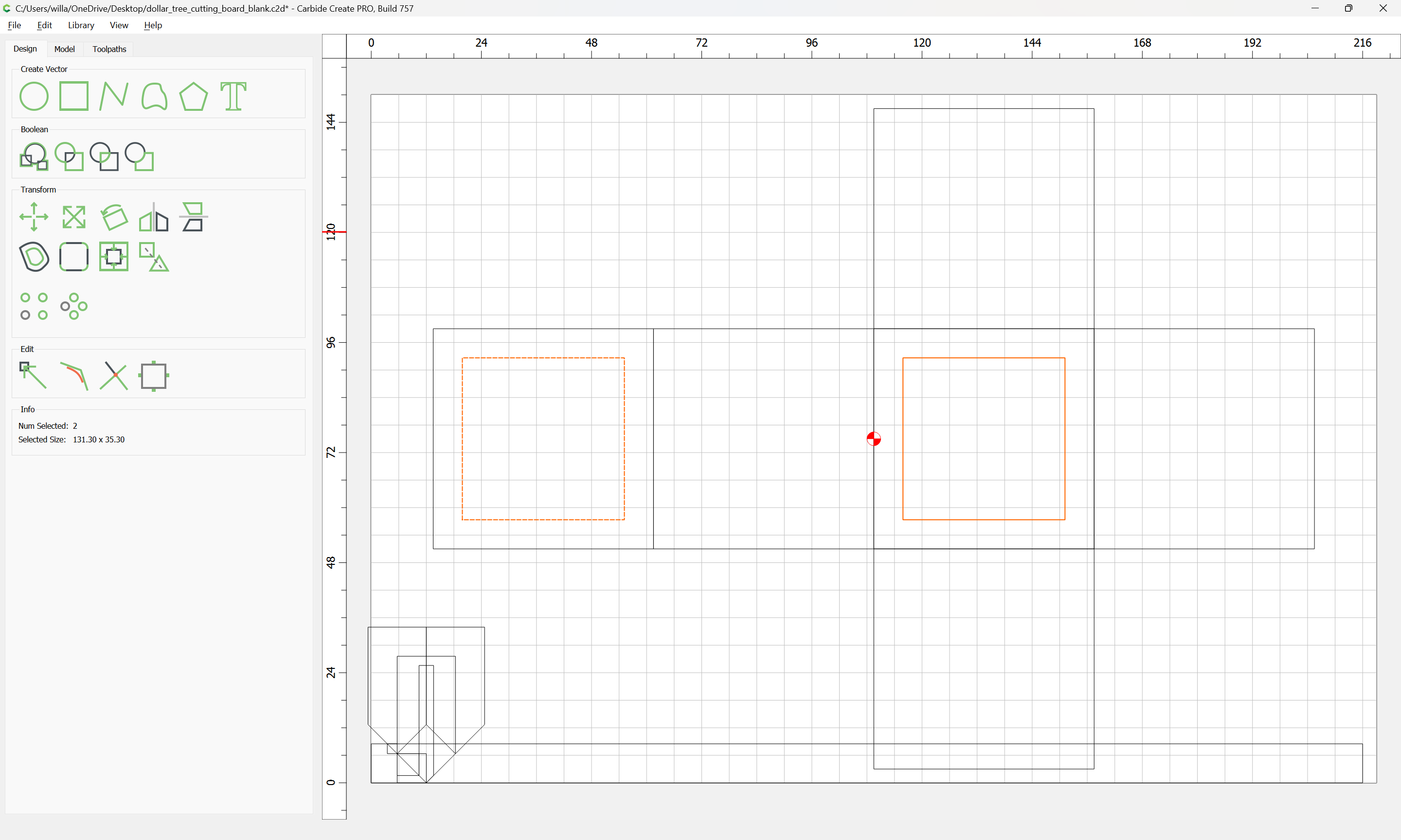
Draw up the geometry of the box:

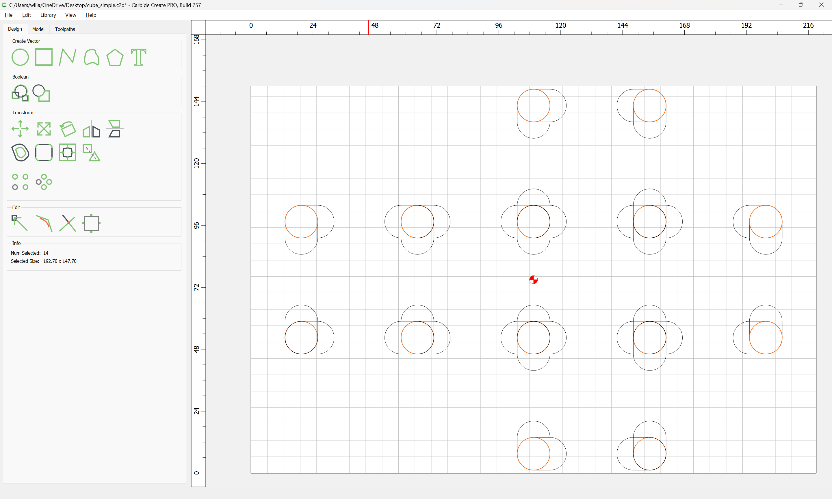
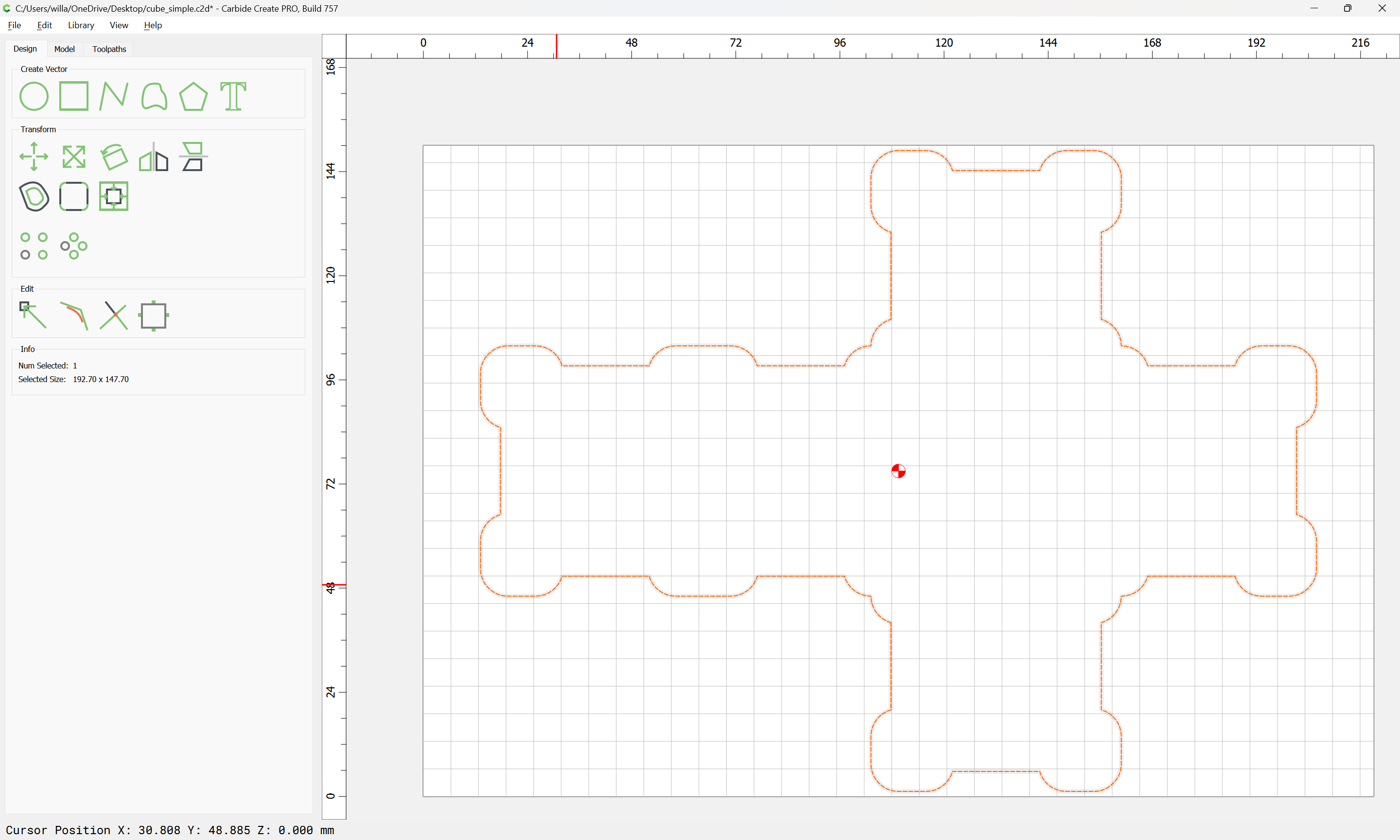
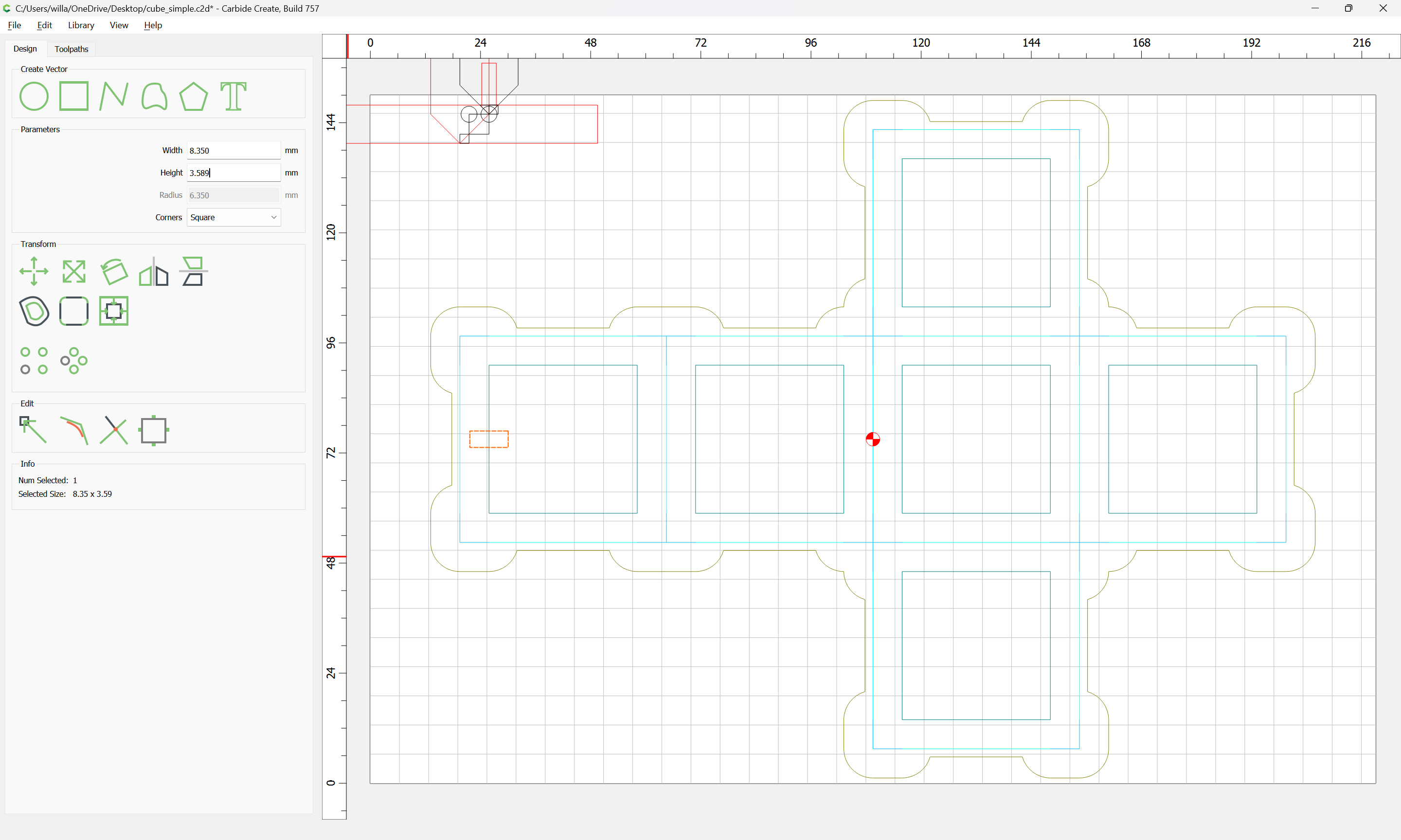
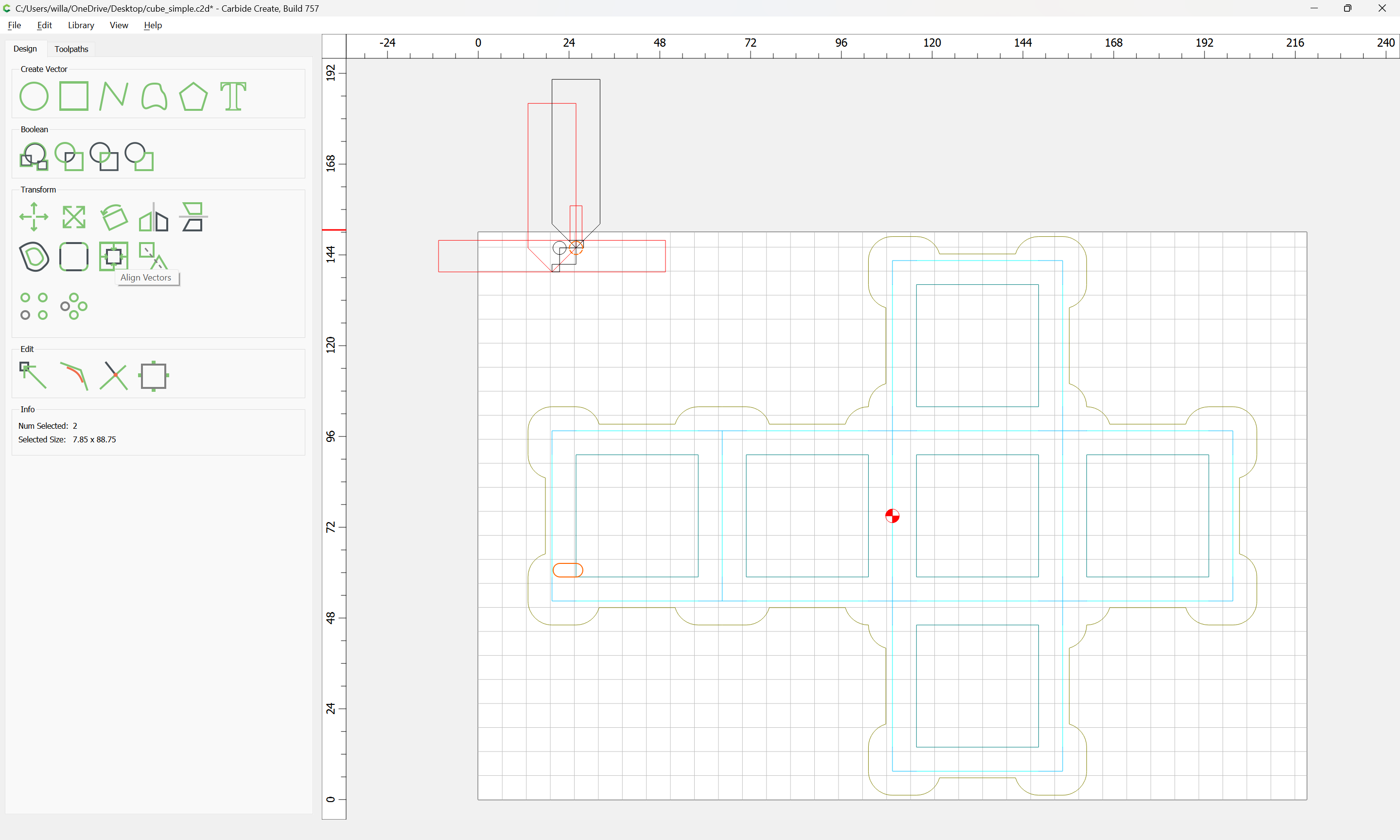
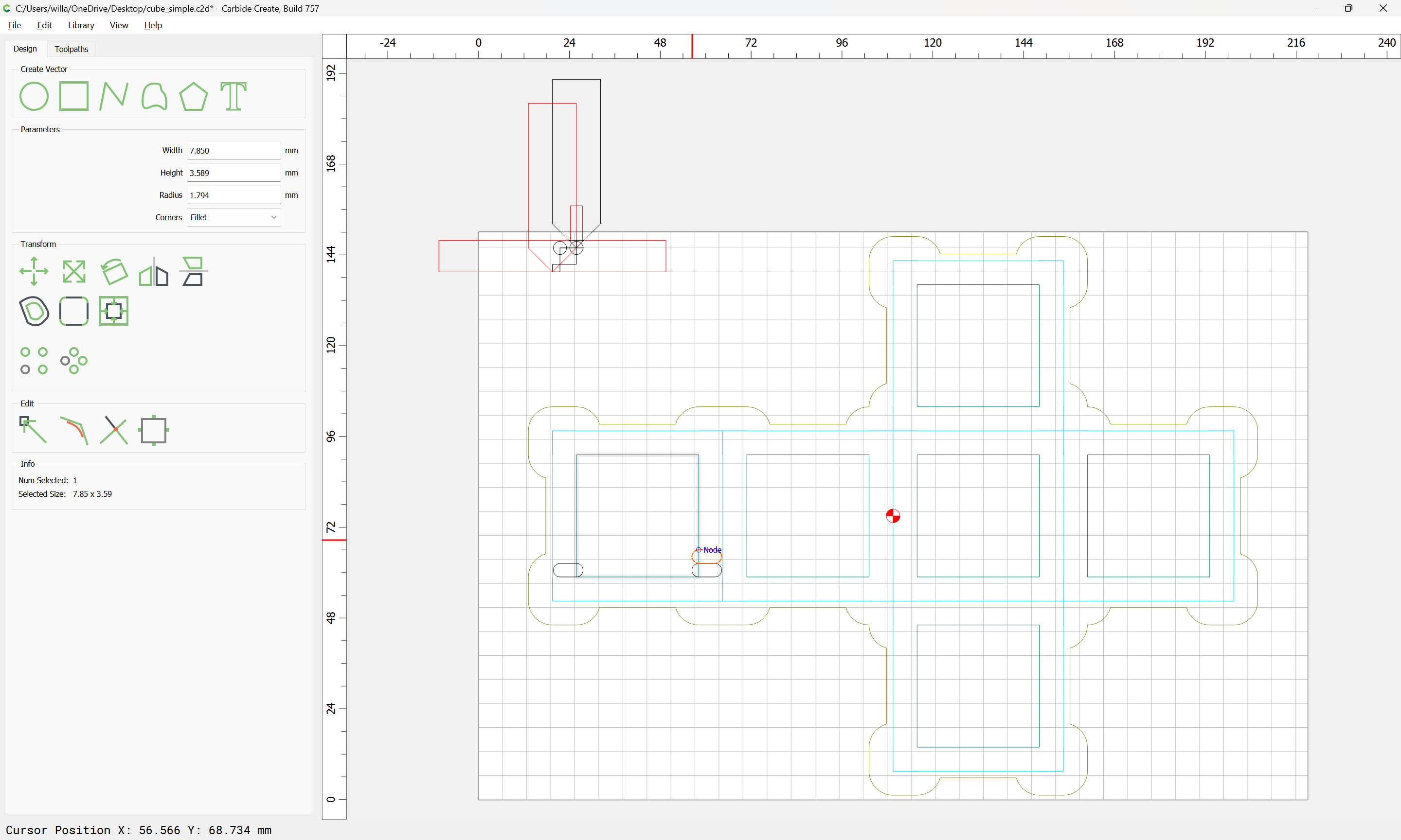
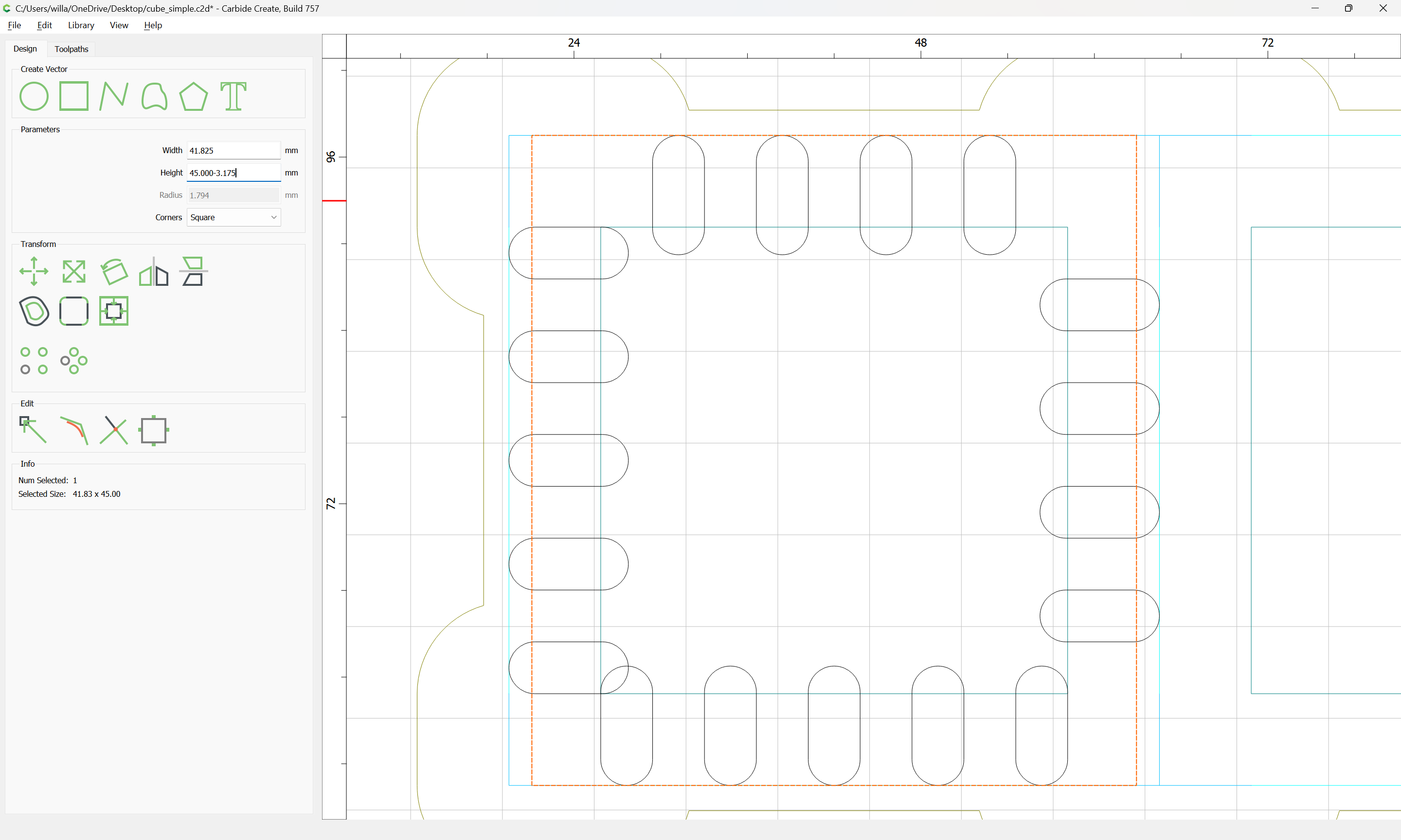
and inset each part by the radius of the large V tool:

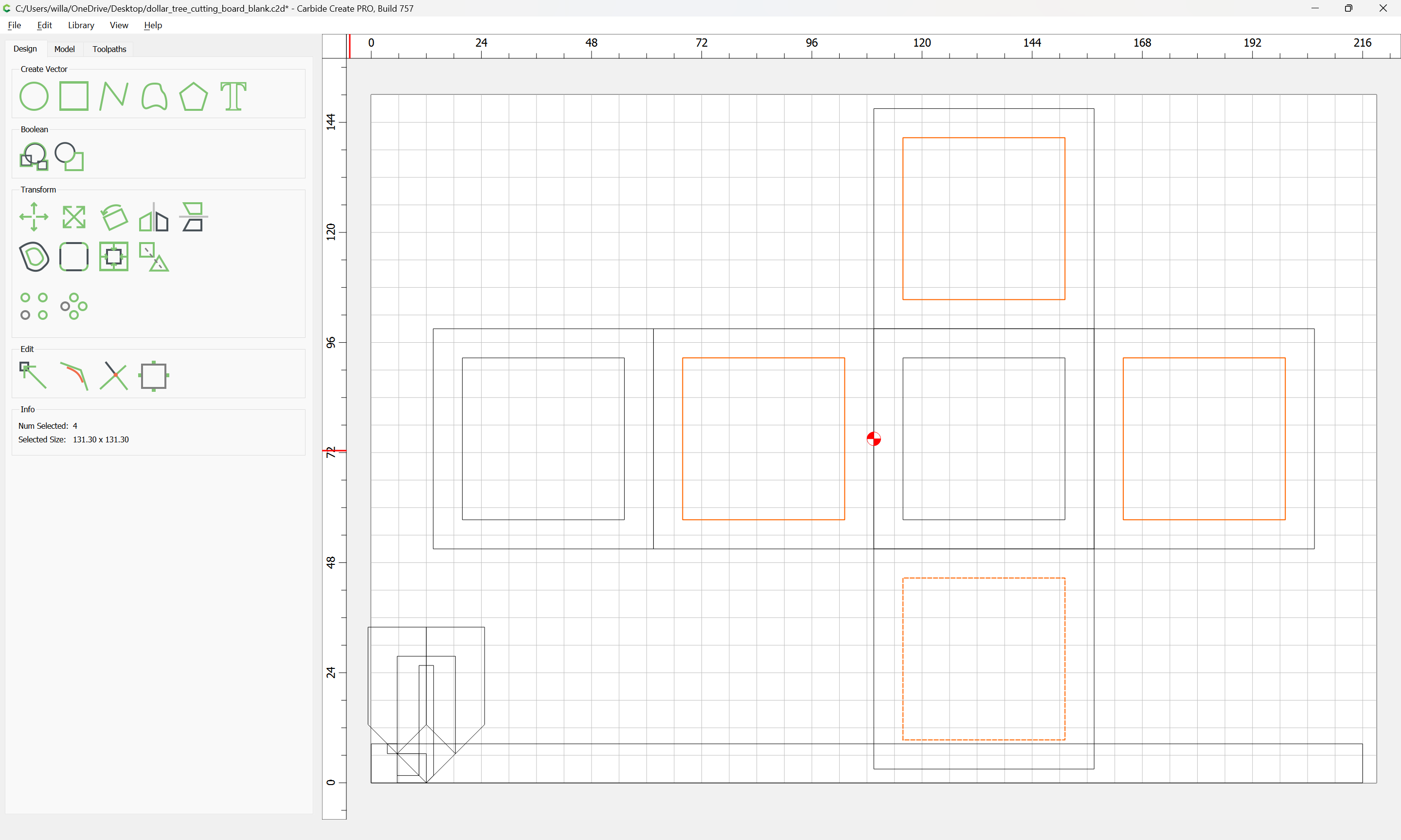
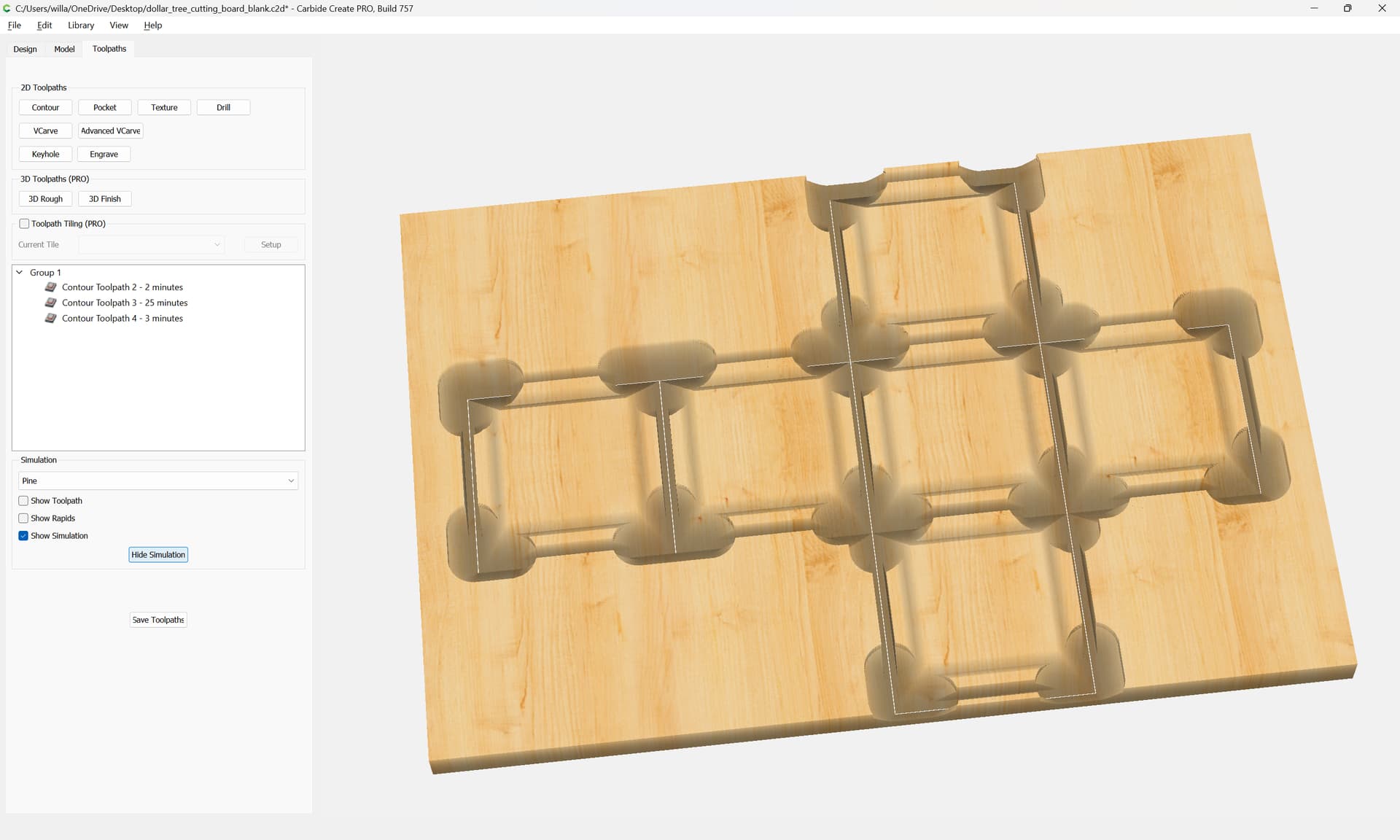
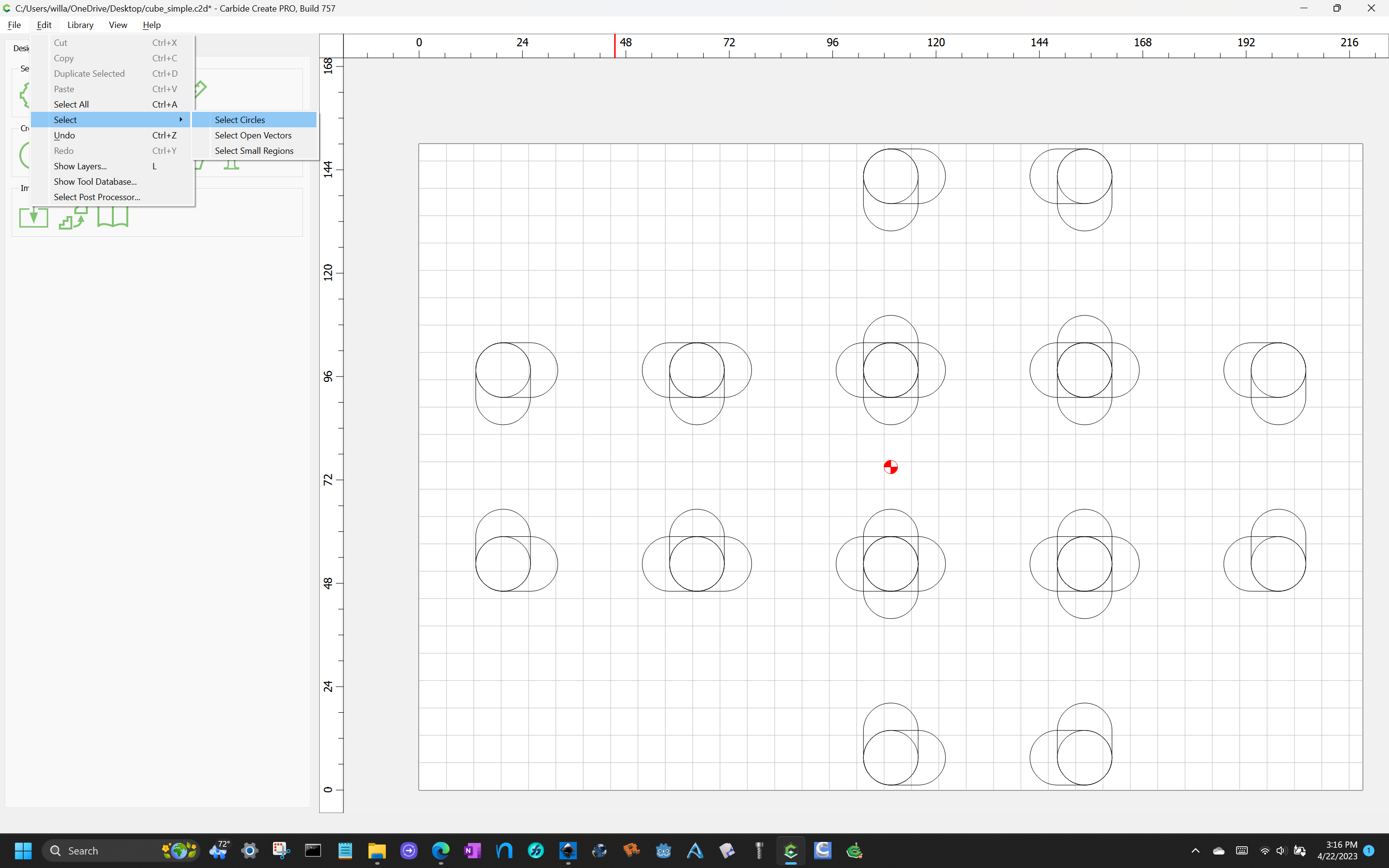
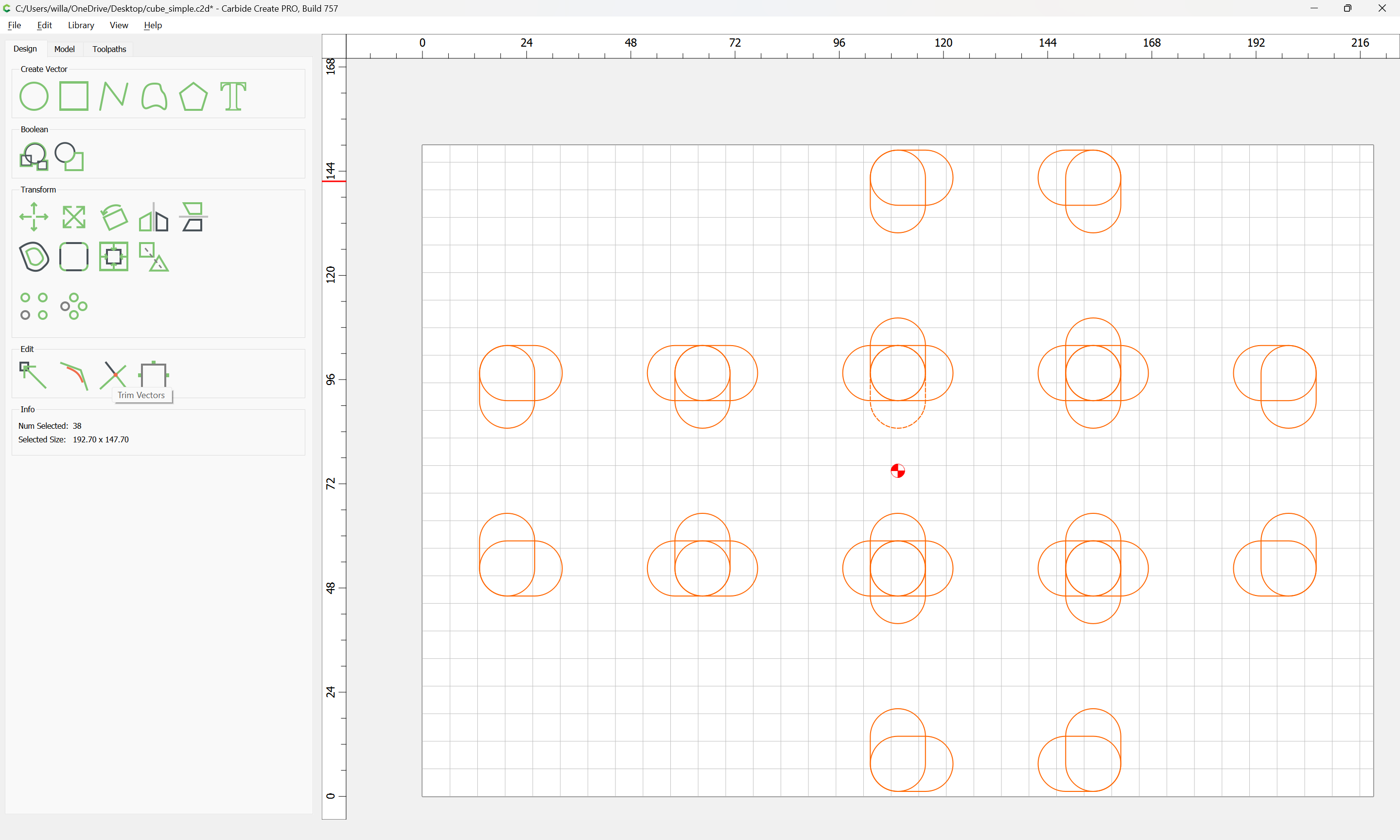
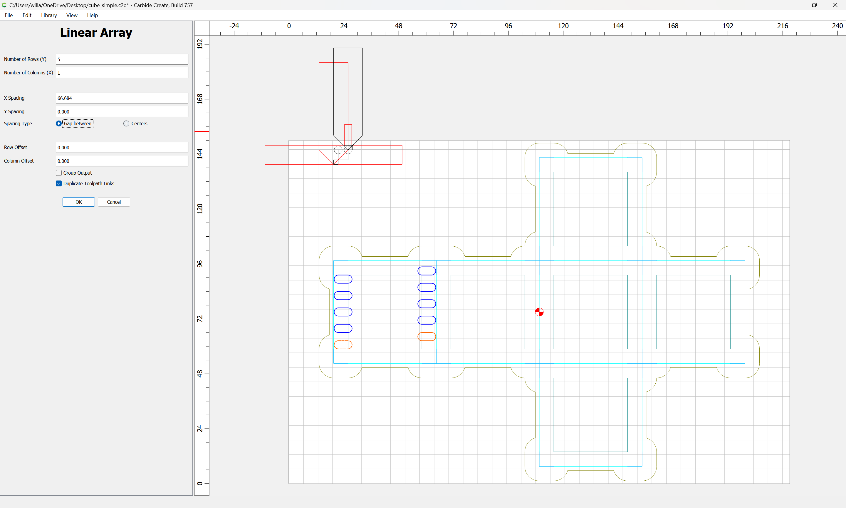
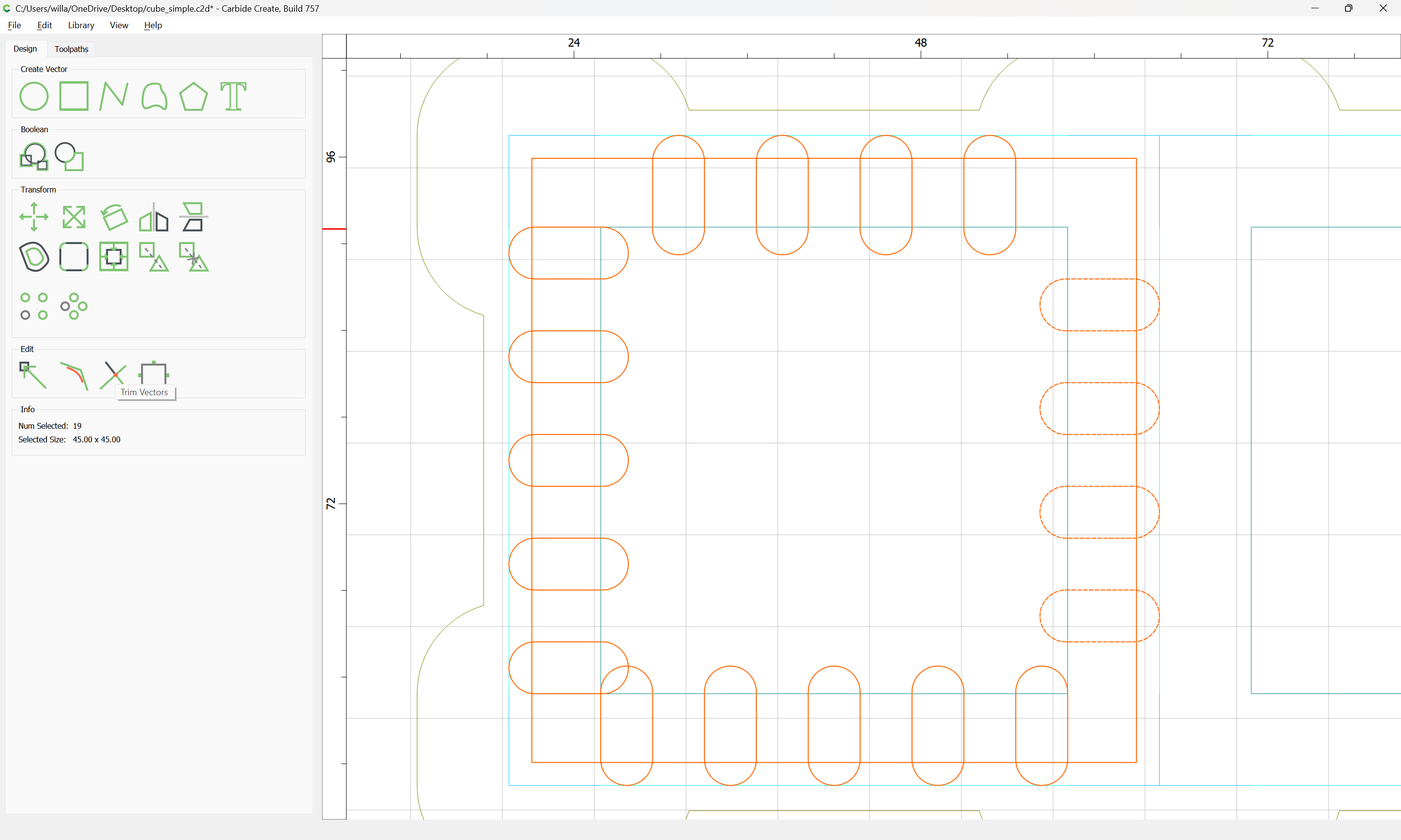
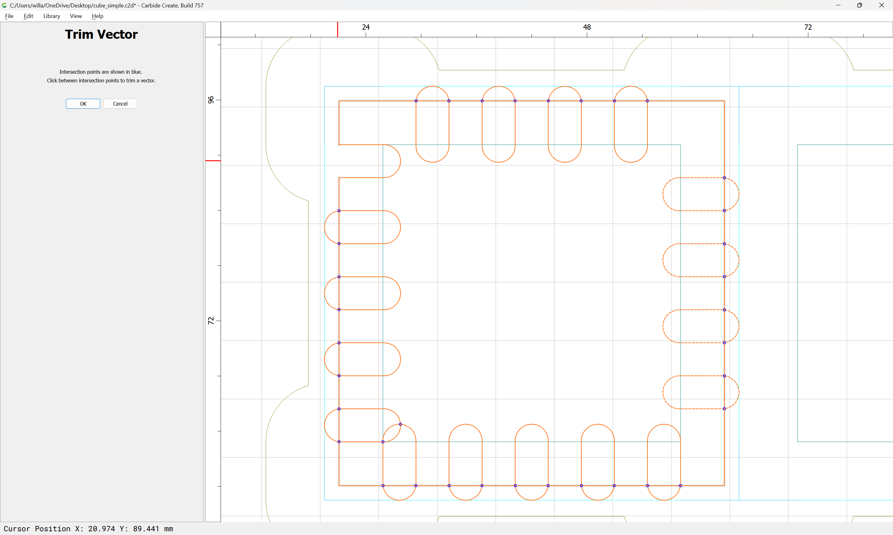
Select all the inset geometry and assign a no-offset contour toolpath to the requisite depth w/ the large V tool:

While it should work to just assign a no-offset contour toolpath to the part outlines, drawing in geometry which efficiently describes the regions in question is an interesting topological problem:

Assign a no-offset contour toolpath at the bottom of the stock using the narrow V tool (note that it will be necessary to ensure that this is cut last):

This geometry should be sent to a hidden layer and if need be locked so that it will not interfere w/ selections:

Draw a square which has dimensions which match the Stock Thickness:

Go into Node Edit mode and Cut the vector:

and then delete the nodes which do not describe geometry coincident with the contour of the part:

Assign a full-depth No-offset contour to this geometry using the large V tool:

Duplicate, rotate, reposition, and if need be, edit for conciseness:

which will all cut as:

Next we draw in geometry which describes where this will cut 2.15mm deep.

1 Like

Move things to appropriate layers, and then draw in a circle at a corner:

We check the dimension which the large V tool is cutting to:

and then draw a rectangle that height, and as wide as the tool:

positioning it so that the center will cut along where the V endmill cuts.

Then add the diameter of the tool and round the corners:

and duplicate and rotate and reposition a copy:

Then duplicate and place on all corners:

and add additional copies of the rounded rectangles as needed:

hide everything else, select all the circles:

and delete them.

Then show the corners and draw in the outline of the parts:

and offset to the outside by the smaller V endmill radius plus 10% or so:

Then delete the part geometry, hide everything but the rounded rectangles and the offset outline and Trim Vectors:

and delete unneeded geometry and then Join Vectors so that one arrives at:

which when selected along with the inset squares:

gets one to:

1 Like

Lastly we draw in the geometry for the box joints and arrange for them to cut.

Profile

Draw in a rectangle to determine the dimension of the pockets for the joinery:

Then divide that dimension by small square endmill diameter plus 10%:

32.3 ÷ (3.175*1.1) = 9.24838941

We need an odd number, so we round down and divide the dimension by that number:

    32.3 ÷ 9 = 3.58888889

Or, just do the math in Carbide Create:

Then draw in a pair of circles to determine the width:

Assign the dimensions and and set the Corners to Fillet and the radius to half of the Height:

Drag it into alignment with the inset:

Then align it with the circles:

Duplicate it and drag it into alignment on the other side:

Duplicate again and drag into alignment with the previous copy:

Delete the previous copy and select both:

Then use the Linear Array command to duplicate:

OK

Delete the extra rectangle:

Then repeat along the other axis:

Draw a rectangle for the part:

Subtract the diameter of the small V endmill from both dimensions:

Select the rectangles and the inset part and use Trim Vectors:

to remove the outer geometry:

OK

then use Join Vectors to close things:

Duplicate and arrange as necessary so that the joinery will line up:

and assign a toolpath:

and adjust the toolpaths for order and begin depth for efficiency:

cube_simple.c2d (304 KB)

1 Like

This topic was automatically closed after 30 days. New replies are no longer allowed.