Accuracy problems in Fusion 360 vs CC

Hello,
I’ve got an issue that’s making my brain hurt. I’ve been using the 5 pro for over a year now, love the machine. Lately we’ve moved from CC to Fusion 360 due to some of the more complex geometries of guitar modeling and carving. I’m starting to get some pretty drastic inconsistencies in cuts - mostly pockets, and the inconsistencies are such that I can’t quite figure out if it’s machine related, software related, a tool issue, or something else.

I decided to run a test, using my main two end mills for the more precision bits of the carving (generally speaking, these are pockets and contours for pickup cavities, neck pockets, and truss rod/carbon rods in the neck)

The drawings I use for generating the sketches all originated in Illustrator, exported as .dxf, and conformed in CC and Fusion. Everything checks out in the sketches down to the thou.

BUT - my pockets in Fusion are distinctly smaller, enough that it’s a problem. I know I could sort out the gap and fix via some negative stock-to-leave, but this seems like a really clunky way to have to deal with the issue. Especially since (as you’ll see below), CC doesn’t have this issue.

In Fusion, I’m using the Carbide 3d Shapeoko 5 Pro post processor (carbide3d 02052026.cps).

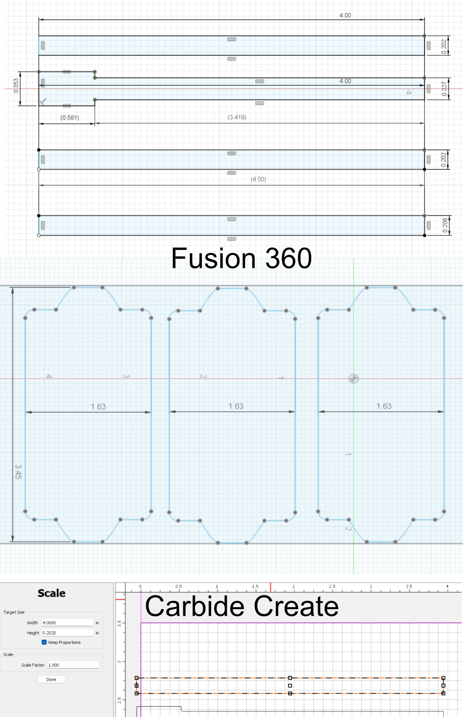
Here are some screen captures of the sketches being used with expected dimensions. The carbon and truss rods are top-to-bottom, all milled with 1/8" endmill:
1st and 2nd: 2d pocket, machined to the sketch (both top carbon and truss rod below it)
3rd position: 2d pocket with .020 stock left, followed by a finishing contour (with ‘repeat finish pass’ checked)
4th postion: machined to sketch, but this one is 0.206" instead of the original 0.202"

The three pickups are:
Left: 2d pocket with .020 stock left, milled with 1/4" endmill, then a 2d contour finish pass with 1/8" endmill
Middle: 2d contour only, 1/8" endmill
Right: 2d pocket, 1/4" endmill only
and here are the results.
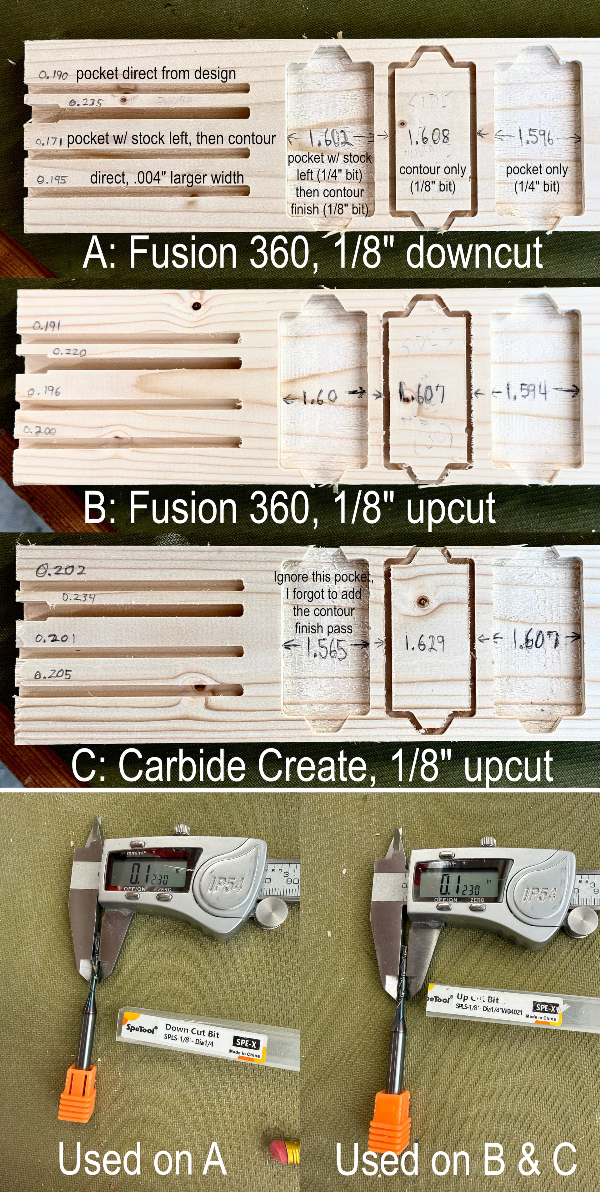
I know there can be some tolerance issues with any machine, and a few thou is totally acceptable (especially since we’re working with wood), but this can’t be where I should set my expectations.

I have done all the maintenance I can think of on the 5 Pro - oil and checking the mechanicals. I’m at the point where I’m pretty sure this is something I’m missing in my Fusion setup. I’ve checked, I’m not leaving any stock on the pockets (unless I’m doing it on purpose to follow up with a contour finishing pass).
I’m attaching my Fusion and CC files here as well. I’m still relatively new to Fusion, maybe 3 or 4 months of really serious diving into it, but I understand the basics enough that I’m pretty sure I’m cutting pockets right. :slight_smile: I could very easily be missing something glaring that’s causing my 2D pockets to be undersized. If so, I would be thrilled to find out what setting I’ve neglected.

Thanks in advance!

Truss and Carbon slot troubleshooting.c2d (96 KB)
Truss and Carbon slot troubleshooting - Fusion360.zip (675.4 KB)
1 Like

I don’t import DXF files into Fusion but I do import SVG files. Depending on which application generated the SVG file it may have to be scaled in Fusion to get the correct dimisions. I don’t have time now but I will look at you files later.

I’m not seeing anything obvious. Looks like your CC file is all down cut bits but feeds and speeds in CC with down cut is the same as Fusion with up cut cutters. When I first started looking I thought it might be feeds and speeds were different between CC and Fusion.

Fusion by default does climb cutting and it looks like CC is doing conventional cutting which could cause a difference. I assume you are using the same cutters and just changing between up and down cut versions.

Not much help here.

I took a look at the Fusion file and I can’t see anything that jumps out as a potential source of error. The simulation in Fusion is also showing me what I’d expect to see - it completely mills the pocket. Once I get my machine up and running, I will give this a test and let you know what I find.

It’s a bit of a silly question, but have you tried a simpler test of milling a single square pocket that’s an inch inset from the origin and is 1" x 1" x 0.25" to verify that an inch is really an inch according to your machine?

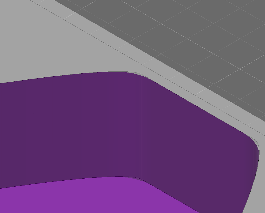
ETA: If you haven’t used the simulation feature in Fusion, it’s helpful and can show you where you’re going to do something REALLY bad (as far as Fusion and the post-processor know). The simulation will also show you where stock is going to be left once the operation is done. E.g., in the portion of the pocket where there are tabs to attach the pickups to the body you can see an small sliver where the cutter isn’t going to remove material (which is fine in your case).

2 Likes

Thanks gentlemen,
Yeah, I’ve done the simulations and am getting the same results you are, everything -looks- correct in-software, but clearly there’s something else going on. If it wasn’t for the fact that the CC version is pretty much perfectly cutting the stuff I’d chalk it up to, well, something.
I’m going to do the 1"x1" test, that’s a great idea. Will do a pocket and a contour with the 1/4" and then the 1/8" bit using both a Fusion generated file and a CC one.

In the Fusion version I am adding a finishing pass to the pocket that I don’t believe I did the first time. In other words I want to give it every opportunity to get as perfect a cut as possible so I’ll have a better idea of what may or may not be off. Also I’ll see if I can’t find a chunk of maple or something to test on instead of the pine I did with the previous test. Might as well use the kind of hardwood I generally am cutting for the guitars.

Stay tuned, I’ll post my findings later today.

1 Like

Maybe check the tolerances on the tool paths in fusion? IIRC the default tolerances can be kind of loose for some applications.

1 Like

I’ll check out the tolerances, I honestly haven’t played with any of that yet.

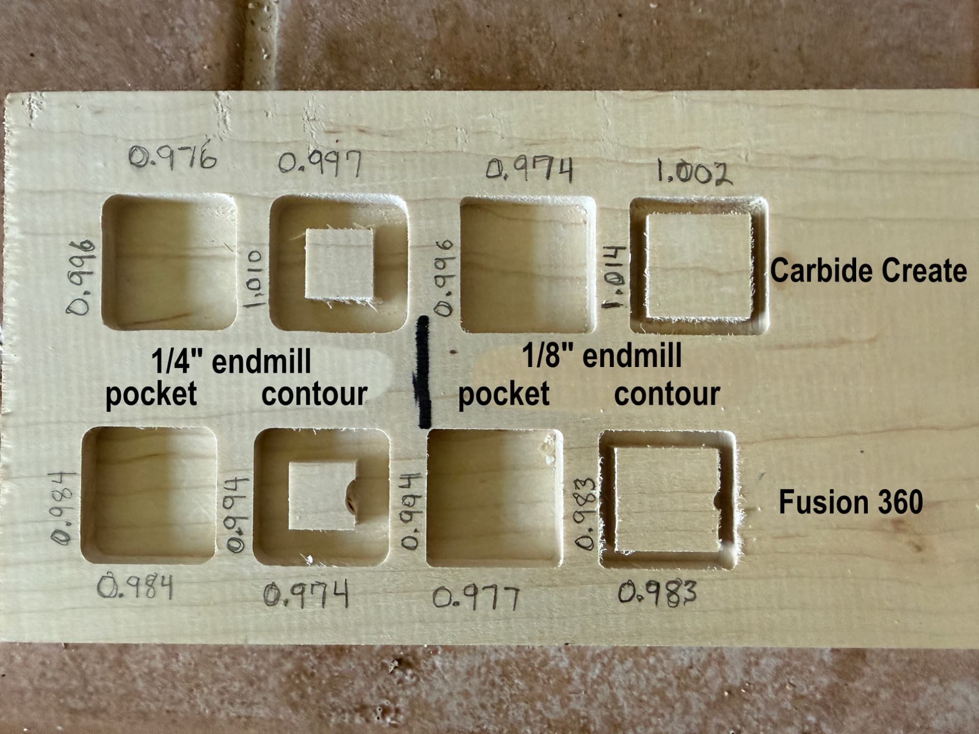
So here’s the 1"x1" test, pockets and contours, 1/4" and 1/8" endmills, Carbide Create and Fusion 360.
Not really sure what to glean from this. Attached are the files. Note - the tool name differences are simply because I built a new tool library in Fusion and organized things differently. The endmills used making this are the same for both versions.

I’ve included the .nc file from Fusion in case that’s of any help.

1 inch squares on 6 x 2.c2d (52 KB)
1 inch squares on 6 x 2.nc (28.1 KB)
1 x 1 test.zip (137.7 KB)

The default tolerance in Fusion is 0.004" which shouldn’t lead to this end result.

I have only been using Fusion or OnShape with my Shapeoko, so I don’t know much about what Carbide Create (with or without the Pro) is capable of feature-wise.

What’s telling here is that the contours have more variation than the pockets. Contouring like this is going to have the cutter at 100% engagement and puts a lot of stress on the tool, spindle, and stepper motors and can lead to losing steps in some cases. I don’t have access to Carbide Create Pro, so I don’t know if Carbide Create attempts a gradual acceleration here, but g-code generated by Fusion will rely on the machine to accelerate at the right rate. An actual ramp (helical or otherwise) is a better option since it will gradually lower the cutter into the material while also moving on the XY plane until the tool is at the cut depth you specified, then the cutting will begin. The end result is that there is less of the end mill engaged in the work piece, leading to less force on all of the equipment, and, in the case of open loop systems, less chance of dropping steps.

With a plunge ramping strategy, it’s possible to miss steps when using open loop steppers like the ones on the the Shapeoko. It’s odd that this doesn’t happen when you generate via Carbide Create, but maybe Carbide Create handles acceleration in software after a plunge, or you’re using Carbide Create Pro and it has more options.

I’m still doing machine maintenance and probably won’t get a chance to duplicate this today :frowning:

2 Likes

The nc files I looked at in ncview for the 1/4 end mills have corner points .75 inches away from each other, so the data is good.

The material looks like pine, which will not clean up very well.

Try a hard wood or aluminum.

3 Likes

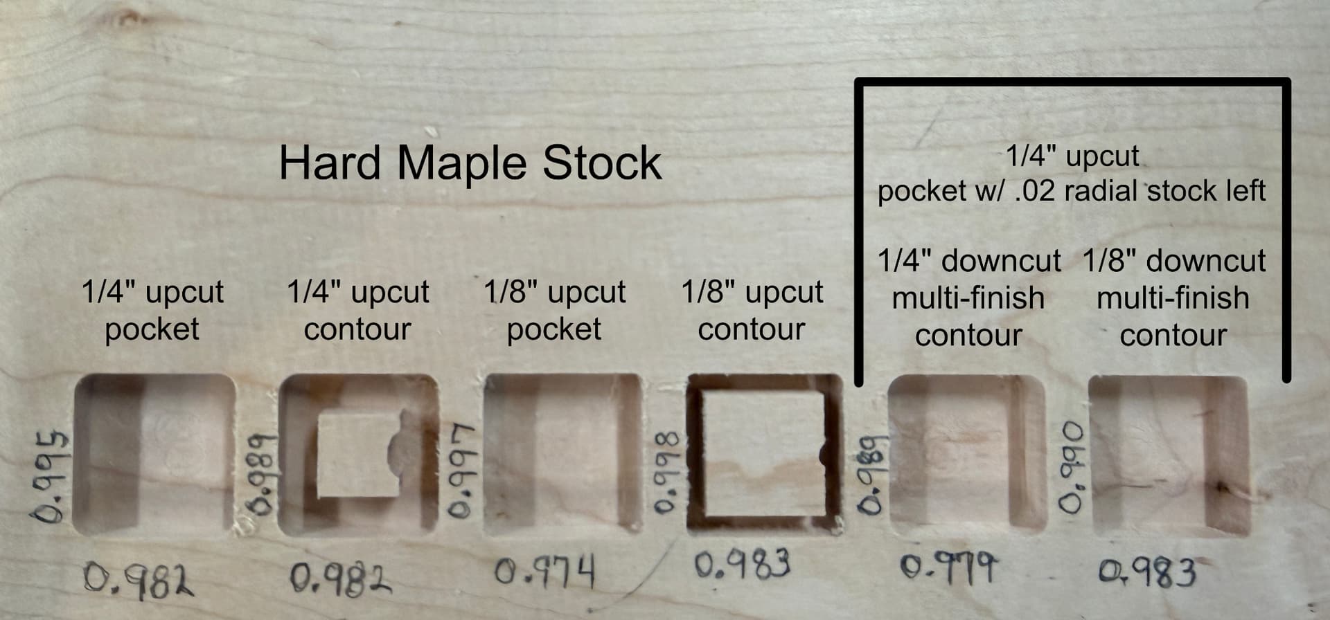
Ok, I bought a brand-new pair of 1/4" and 1/8" upcut bits and spent the entire day re-building my tool library from scratch, importing data from the manufacturer whenever possible (trying to eliminate any screwy data from my own brain). What caused that thought is when I tried to run another test a couple days ago, what should have come up as “tool 101, 1/8” upcut endmill" in Carbide Motion showed “tool 101, 1/8” ball nose". I figured there must be some weirdness in CM reading my old library from Create. Since I’ve been meaning to really think through my Fusion tool library anyways, I bit the bullet and spent all day making it right, then manually rebuilding a new Create tool library .csv, so in theory, both libraries are identical.

Well, after all that and hiding my old library from Create it still called tool 101 “1/8” ball nose" so I have no clue where CM is pulling that info.

Anyways. Here’s what I got. Still seeing the same couple-hundredths of an inch problem on the X axis, and a few thou on the Y. I did multiple finishing passes on all operations (except maybe that first pocket) to hopefully account for any deflection. Material is hard maple, I don’t have any aluminum on-hand at the moment.

I didn’t do a Carbide Create pass this time, might do it tomorrow, but I feel like I’ve eliminated every variable I can and it’s still off. I’m really hoping this isn’t something I’m going to have to live with and figure out how to adjust X-axis cuts differently than Y-axis cuts, that seems hellish. The baffling part is still that CC pretty much nails the sizes, at least in the previous test. Will do this one in CC when I have some time.

Attached is the new Fusion file, and here’s a pic of the results.

6-pocket test, new tools.zip (215.4 KB)

1 Like

TL;DR - I think that this is not a Fusion post processor issue: the g-code is correct. There is a tool path issue in Fusion that’s leading to the machine losing steps.

What do I think is happening?
This is what I think is happening:

  • Both Carbide Create and Fusion are generating valid g-code, but they do it in different ways.
  • CC is likely controlling machine acceleration to reduce strain on the machine. (Or you have CC Pro and it does something to the tool paths that I can’t see in regular CC.)
  • Fusion’s g-code puts a lot of stress on the machine and it’s losing steps.
  • Because of this, the g-code from CC produces the accurate cut you’re looking for.

Why do I think this?

  • As @jtclose pointed out: the g-code in NC files from Fusion is correct. The coordinates point to Fusion’s post-processor doing everything correctly.
  • Fusion’s default entry to a cut is a plunge. I do not know why, but it is.
  • Plunge entry into a cut puts a huge amount of stress on all aspects of the machine, from cutter to steppers and everything in between.
  • When the machine can’t push past the resistance of the material, you are losing steps. (This is better than some of the alternatives like throwing the part or snapping the end mill.)

Questions:

  • In the Fusion tool paths, you’ve still got ramping set to “Plunge”. Is there a reason to keep that?
  • What is powering the end mills? Router? 65mm spindle? 80mm spindle?

How do we fix it?

Using some kind of “proper” ramping.

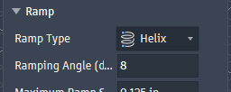
In Fusion, double click on a tool path, then click over to the Linking tab (last tab on the right), head down to the “Ramp” section, make sure “Ramp” is enabled, and then set the Ramp Type to Helix and Ramping Angle to 8.

Why helix? It’s slowly spirals into the material before beginning the actual cut. There’s very little strain placed on the tool and you can avoid situations where you could lose steps or snap the cutter.

Why 8 degrees? The default of 2 is too low for wood, you’ll be ramping forever. 8 is a good start to tune to your work and your machine.

Making this permanent
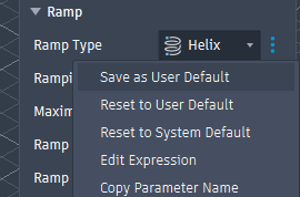
If you hover your mouse just to the right of the input box, you’ll be surprised by three dots. Once you’re happy with a ramping strategy, you can click the three vertical dots and select “Save as User Default” and then you’ll only have to remember this when you need a tool path to be different. Do the same for the Ramping Angle.

Why haven’t you tested this yet, Jeremiah?
I’m still waiting on a spindle motor extension cable to arrive so I can test this, although I’m not confident that I’ll be able to reproduce it. I have closed loop steppers that are larger than the stock steppers and I also have an 80mm spindle.

Pretty sure Carbide Create usually plunges — ramping in is a Pro option.

Usually, when there’s a subtle difference between part dimensions, one thing to consider is the difference between climb and conventional milling.

My understanding is that Fusion 360 has very sophisticated toolpath options (some may need to be paid for?)

I would work up a matrix of all the possible options, research which ones are considered best practice for the material(s) being cut, the tooling being used, and for routing on a lightweight/non-industrial machine, then do an iterative set of cuts, measuring at each step to see what one can learn.

FWIW, when I’ve needed the best possible precision/accuracy, my approach has been to:

  • make a roughing cut leaving some nice round value of uncut material which is easily accounted for when measuring
  • after measuring, adjust for a finishing pass, but again, leave a nice round easily measured value as a target thickness of uncut material (which is at least 2 times, better 4 times chip thickness)
  • measure that cut and then adjust for a finishing pass which leaves exactly chip thickness of material uncut
  • measure that — if still undersize, make the final cut after adjusting to remove one chip thickness

It’s tedious, but the fit is very satisfying.

I will further note that you need to have very good metrology gear for this — best is to have a tool which is ten times more precise than one chooses to measure to (ignore that last digit) — I have a pair of micrometers, and I’m willing to use them (when measuring lengths w/in their range — donations towards the purchase of a boxed set of graduated micrometers will not be accepted, no room, and I don’t do this often enough, not even playing the part of a wannabe machinist on YouTube…)

2 Likes

Fusion was a steep curve at first, but it’s definitely exceptionally powerful as you dive into the options. I haven’t found much inside a toolpath that’s exclusive to paid Fusion, but the Manufacturing extension gives you 3+2 and 5 axis machining as well as some other really nice toolpath options. Basically if it can rotate around an axis or go real fast, you’re paying for it :stuck_out_tongue:

@WillAdams’s iterative approach is how I approach this kind of thing, too. Even though you’re doing “the same thing” you were doing with CC, but now with Fusion, everything has changed apart from the material and the cutter. Fusion will really let you dial in the fit that you’re getting.

In a recent project, I cut box joints on my machine that fit perfectly right off the machine, no fettling needed. The whole project ended up being like that, too, so all I needed to do was design effectively. But this comes from a lot of mistakes with Fusion and figuring out exactly how things need to be set up for my machine and the materials that I cut.

As you dig into Fusion more, you can create template toolpaths (e.g., “1/4” downcut pocket in hard maple" or “finishing full depth”) so you don’t need to remember anything after you’ve dialed it in. Templates and user defaults will be your friend.

2 Likes

I’ll bear that burden for you Will.
If anyone must donate towards the purchase of a boxed set of graduated micrometers, feel free to send it my way :stuck_out_tongue_winking_eye:

3 Likes

This is all fabulous information - I can’t thank you all enough!
The helix ramp -is- the default in Fusion (at least for pockets), and yes, there is a ramp feature in CC Pro, tho I’ve never used it, so in the past my CC cuts were all plunge. Since it was the default in CC I just sorta figured that was the norm. Also since my early mucking about with a helix ramp added something like 15/20% to my machining time I abandoned it. Didn’t even think about changing the angle. Man. SOOOO much to learn! :stuck_out_tongue_winking_eye:

(I mainly got the Pro version 'cause it would do 3d stuff and quickly found the grayscale bitmaps to not work for my guitarish needs…thus Fusion!).

I’ve worked up another version of the test project doing ramps on everything as well as adding an outside contour operation to see what can be learned from that.

Should have that knocked out in an hour or so, and will report back!

2 Likes

Ahhhh, cool! I have forgotten which settings are defaults and which are my defaults.

On ramping - I’ve gone as high as 12 degrees for the entry but I’ve seen more. You can also increase the ramp feed rate as you get used to your machine and materials. The defaults are intended to be safe and sensible so that programmers/operators can know that if something is done with defaults, it won’t crash the tool turret into something on the fancy new million dollar machine.

Fusion is a big beast, but there are a lot of great tutorials on YouTube, both about Fusion in general and using Fusion to build electric guitars in specific. Mark Guttierez uses a Shapeoko to build his custom guitars, may be a good place to start.

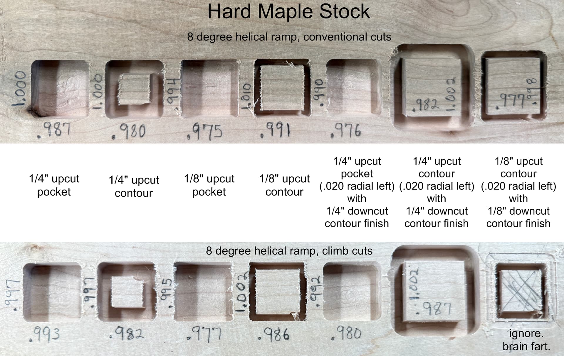
Ok, latest test. It’s becoming clear to me that I’m losing steps on the X axis, that seems pretty consistent across everything I’ve done (including a couple observations on actual projects over the past few weeks). Problem is, I don’t really know what to do about that. I feel like I’ve done all the maintenance-ish things you’re supposed to.

This time around, I did the ramping, which seemed to help a little. I did these with the default ‘left’ aka ‘climb’ setting. (bottom of image)

Then I did another one where I changed two things (top of image) - first was changing to ‘right’ aka ‘conventional’, but also after seeing those ‘bites’ the bit takes out of contours upon ending the cut I selected ‘perpendicular’ on leads and transitions, I wasn’t happy with the sound it would make when jumping out of the end of the cut, that felt like a broken bit waiting to happen. Will read more about this.

Pocket Contour test 7 boxes.zip (207.3 KB)

I’ll definitely give Mark a shout! I met him through the Great Guitar Build Off a few years ago and have talked with him now and again. Great guy, great guitars!

1 Like

How are you holding the stock to the table ?

1 Like

If you are getting better results from CC, I suggest you export the CC gocde and compare it to the Fusion gcode. It just text files.

1 Like

Five hold-down clamps, it’s not moving at all. :slight_smile: