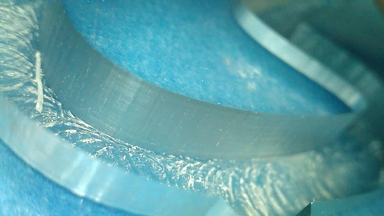
Same run at $12=0.05.
Looks identical to me 
So I had another look at the G-code for that curve, and it looks like this:
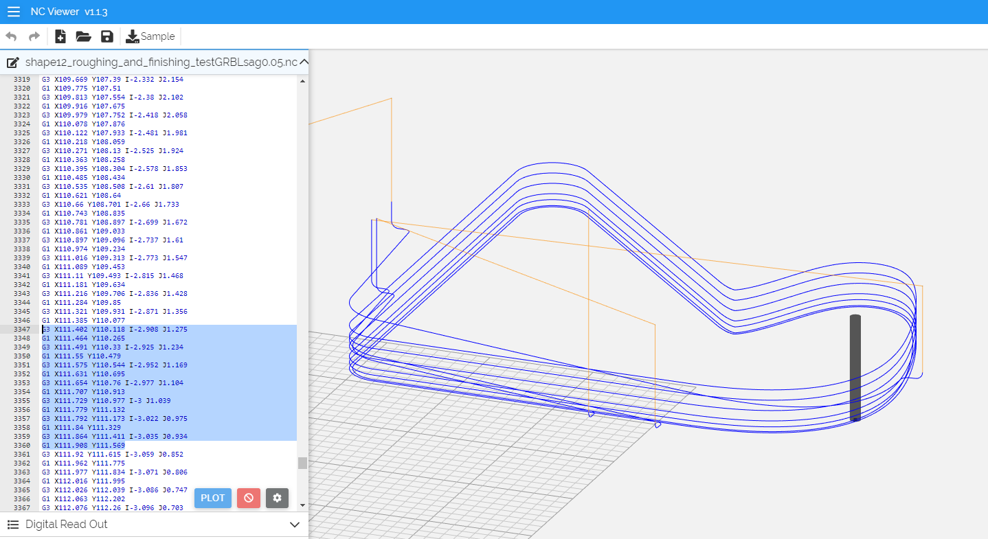
it’s a succession of very small G1 linear moves and very short G3 arc moves. I guess this is why $12 is irrelevant? (i.e. the arc length is so small that it does not even get to break it down into multiple segments?)