@Omar thank you for posting this, using my laser to check for the same effect was on my list of things to try, so this kinda proves that itâs not an interaction with the material and it is a mechanical âlimitationâ indeed.
@neilferreri: great idea. I would ask @stutaylo to try it for us if he was not stranded in a hotel room. Maybe @patonclover can tell us whether he usually gets similar marks in curves using his Masso.
Itâs funny how I never noticed earlier the effects that those 40steps/mm can have, in 99% of the cases itâs invisible, but acrylic has a way to make every tiny detail stand out.
@Microwave_Monkey: first I need to start by unboxing the (supposedly) 120fps camera I received yesterday (and did not even have a chance to try with all this acrylic excitement), and then if slow-mo cuts become popular to investigate cut quality, weâll see about invoking the Shapeoko Seven
@Vince.Fab thanks for sharing those pics, interesting. I would expect the spacing of the marks to be variable (closer to each other when the tangent to the curve is near 45° off axis, and getting larger as the angle gets close to 0 or 90°, but on such a small piece itâs hard to tell. I would like to try and do the same cut in acrylic (would you mind sharing the file or at least the outline of that part so we can compare apples to apples ?)
Me too ! Iâm afraid this will do nothing to help me control my Nomad3 lust, but Iâm willing to take that risk
Thumbs up for that effort to reveal this machine limit!
So I gather that the machine travels on a grid with 1/40 mm spacing, approximating the target curve as best as it can w.r.t. to the tool diameter.
And now I wonder if the marks would probably shift for differerent tool diameters? I mean of course it would be a different path, but maybe the approximating path drops into a different pattern if you use, e.g., a 3 mm vs 1/8" bit.
Didnât think this through, but doing multiple finishing paths could lead to smaller marks, if the individual patterns overlap?
This is the funny part: the machine is actually very, very repeatable in how well it follows the generated (segmented) toolpath. All the latest cuts above have two finishing passes around their perimeter, and it does not change much, if anything.
The best example is that 1 degree straight line: thereâs only way for GRBL to go from the beginning to the end of that line, and the places where the subtle âitâs now time to do 1 microstep to the rightâ moves will happen will always by the same, so repeating the movement should not change much.
If one were a complete psychopath, for a perfect circle that translates to a single G2 arc command, there would be a way to overlap a multitude of overlapping arcs with slightly different starting points, i.e. change the starting point if the arc along the circle by say 1degree, run a pass, move it 1 degree further, rerun the pass, etcâŚrinse and repeat, until the segment/marks are blurred out all along the contour. This is purely theoretical, and of course I was not crazy enough to think of trying that (*cough *)
Letâs say you want to approximate the green path by moving the probes (red and blue) along the grid.
And letâs assume a very conservative approximation is done, so that you may never cross the shape with your probe.
For the given example the red probe can get closer to the shape than the blue one.
Thatâs why I assumed that differently sized tools may produce different marks: no need to shift arcs or something like that.
However, while writing this I realize that the fraction between the tool diameter and the grid spacing is so large that the probable shift of the marks would be extremly low and hardly noticeable.
1" circles in 6061. $12 - 0.001
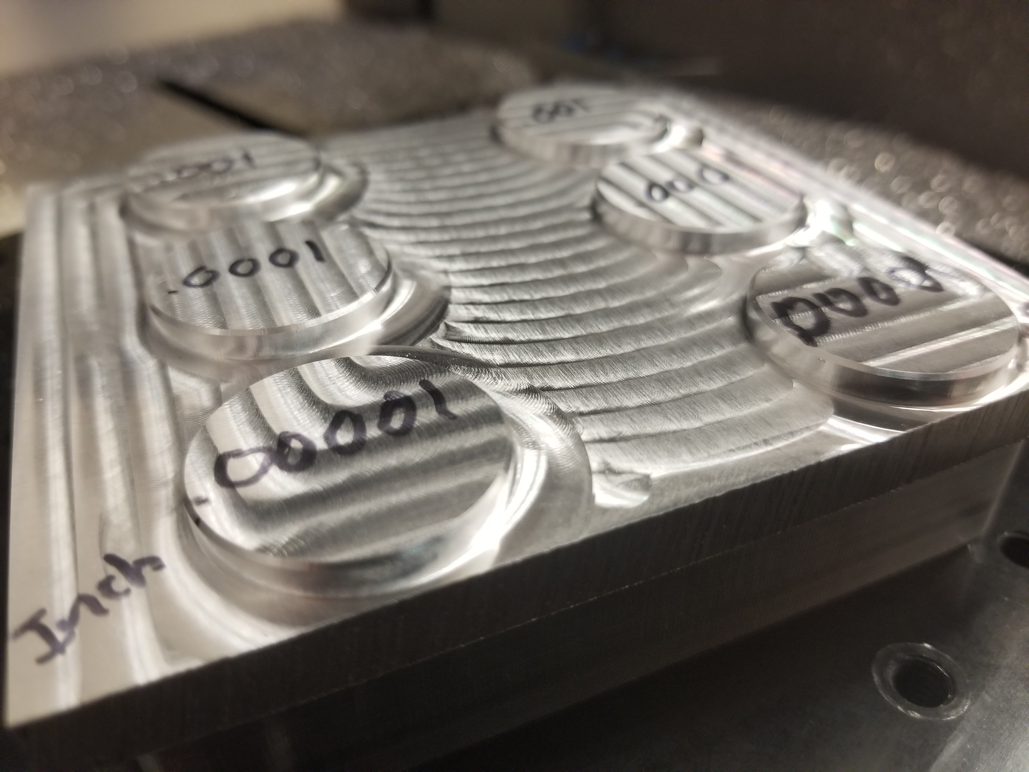
0.125 deep, adaptive with 0.01 left then a bore with spring pass. Left row is set to 0.001, 0.0001, 0.00001 tolerances, right row set the same but exported in mm.
Lines are very very slight but itâs still a really good finish and youâd have to look close. Honestly canât really tell any differences between the tolerances.
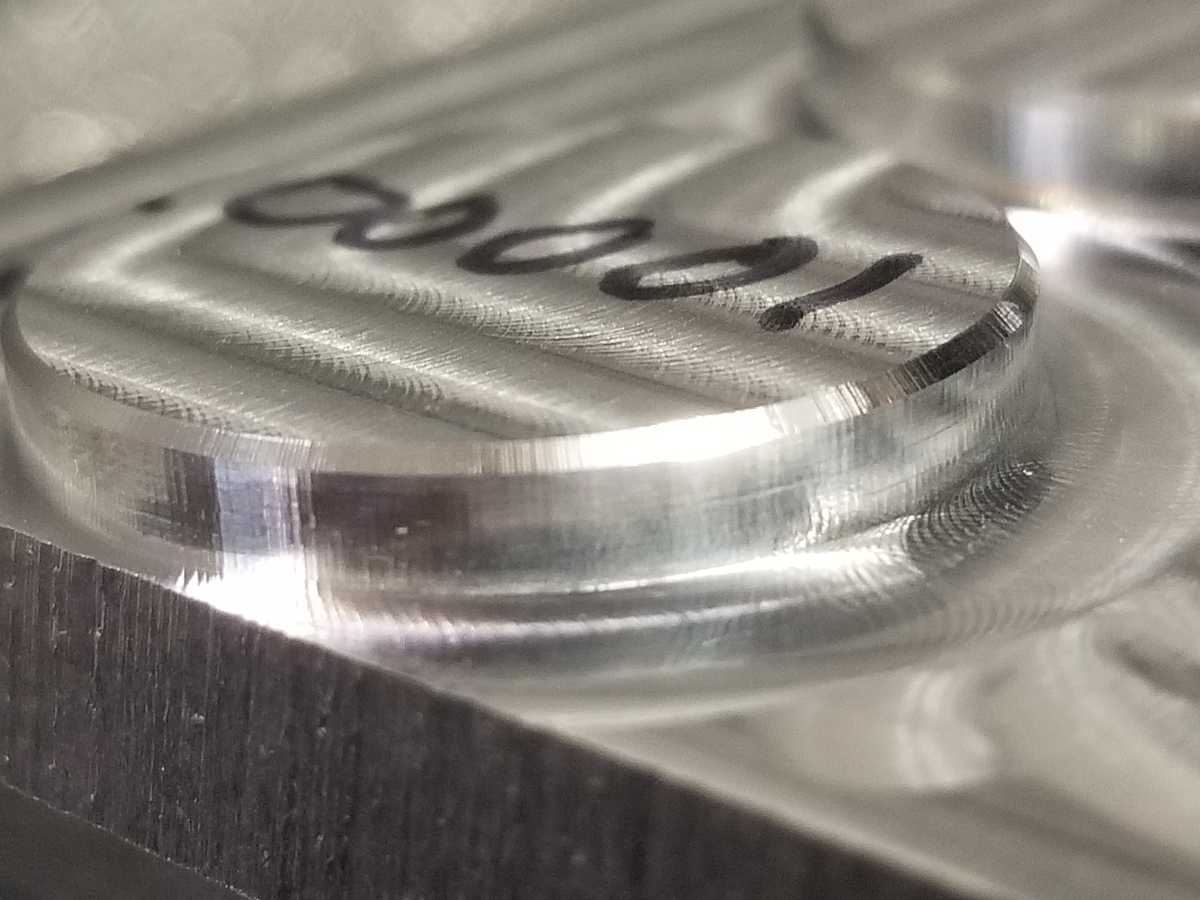
When you output a cut file with curves, you should use a post processeor that uses ARCs. I donât use Fusion360, but I think that V-Carve shapeoko post processeor doesnât do arcs by default. Pretty easy to modify to add them in there.
In V-Carve curves are different then bezier curves and beziers will get output as a bunch of segments even if you save with a pp that has arcs
Try outputting a file that you KNOW uses arcs and not lots of tiny segments.
The Shapeoko post for Fusion360 does use arcs, itâs actually one of the first thinÄŁs I checked, and the steps are there even with arcs (as they should, since itâs just the machineâ s resolution limits showing up in those cuts)
Here is a YouTuber that does high-end custom PC mods and he does really great work in aluminum and acrylic. His acrylic work is especially relevant for this thread and might be worth checking out. He doesnât spend much time explaining his set up or his speeds and feeds, but you can pick up a lot just watching. Iâve linked to part 8 of his most recent build because it is his best example of acrylic machining. He also works in acrylic in part 9 and he talks a little more about how to achieve a good finish.
Quite interesting thank you, I found myself watching the full 23 minutes.
This guy must be @Lukeâs hipster cousin or something ?
Thatâs a beautiful piece he made, but I was interested in that part :
Funny how he mentions that âif you have something like a Shapeoko with a Dewalt router this wonât workâ , which is true since he mentions a max speed of about 400 RPM. Enter the modded Shapeokos with water-cooled VFDs, and I now have ONE MORE THING I need to try
Iâve been using a cheap 10mm edge finder in my VFD spindle for a while now, itâs invaluable for those times where you donât have a square flat piece with a WCS on the bottom left corner, and for not forcing you to set up that way. Mine says 1,200 RPM as the target speed.
Some of the earlier parts are interesting too. In part 2 he describes having to move his compressor away from the CNC because it was putting marks in the workpiece when it started up by shaking his machine.
Hi @Julien, maybe a little too late here, but did it ever occur to you that this might have to do with how F360 extrudes 2D curves into bodys? My thought is that while you have a 2point arc on the sketch⌠when you extrude that into a 3D body the 2point curve actually transforms into a multi-point vector arc along the bodys curved edges. Food for thought, visually thats how it shows in F360s webbased viewerâŚ
Hi @MarkDGaal, yep there are definitely lots of small arc segments in the generated G-code along the curves (as can be seen in that earlier post in this thread), and it seems that GRBL turns arcs into tiny linear segments anyway. But those segments are very small, an order of magnitude smaller than the periodicity of the tool marks on the piece. A test I did early on is to cut a perfect circle: the generated G-code was then made of exactly four 90° arc commands, and still the marks were there. I also tried Fusion360âs âsmoothingâ options to minimize the number of subsegments along curves, to no avail. That and measuring the toolmarks spacing along a 1° line kind of convinced me it is (only?) stepper quantization, but I would love to change my mind if someone came up with a smooth curve in acrylic on a Shapeoko!
Not exactly applicable. Probably best to rezero after those CNCjâs soft limit alarms?
I hit a slab of .375" cast acrylic at my full rapids speed, whatever the max jam I could cram is, and it ripped full .375" material and a stack of wasteboard before even starting the ramp. I didnât know what happened, rechecked the fusion file and post, nothing wrong, rezeroâd, started the op again. Very little contact on the 2nd attempt op. The roughing vs finishing limits are probably quite interesting.