Hard to tell for sure. The periodicity seems to be constant.
4 Likes
You might try cutting a straight edge that is 1 degree off axis; if the marks are about 1.5mm apart then I would say it is a limit of the machine resolution of 0.025mm/step. (or, replace your belts with ball screws and see if the spacing changes proportional to the steps/mm change)
4 Likes
I think you are on to something here and this was the right test to do!
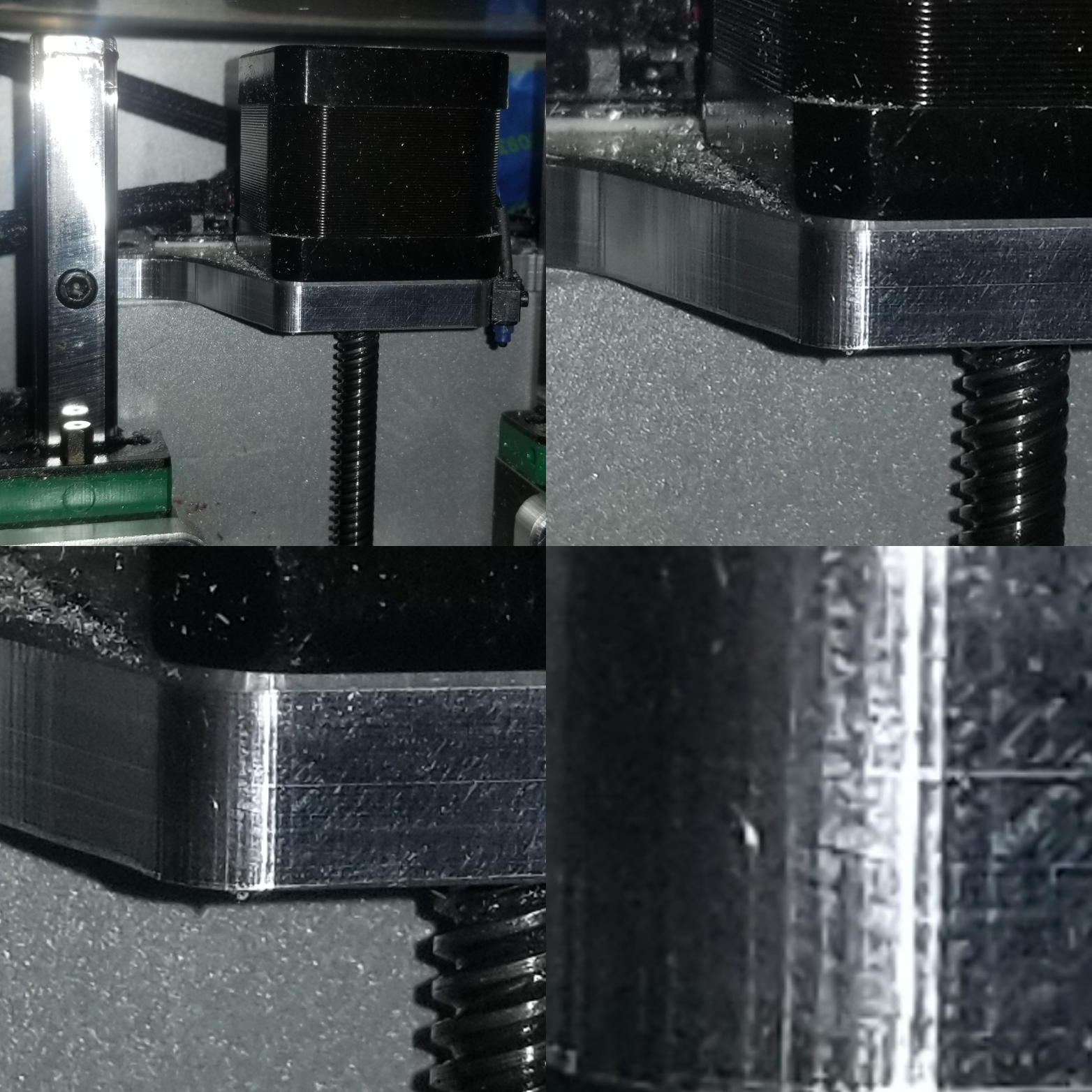
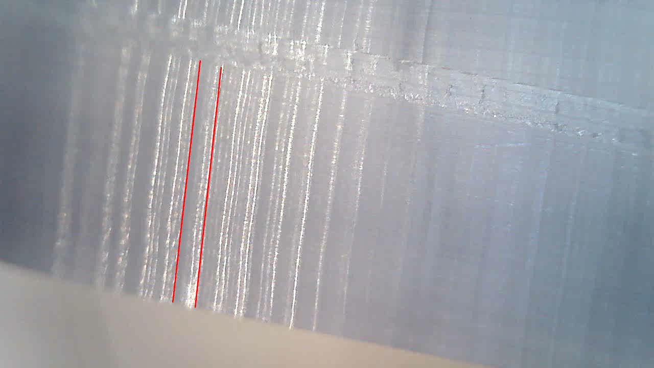
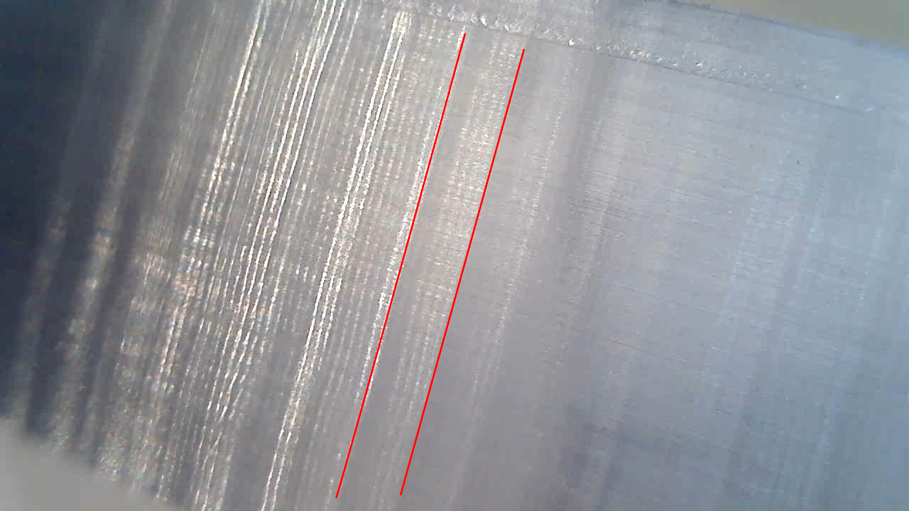
I did it, and the 1° off-axis wall looks like this:
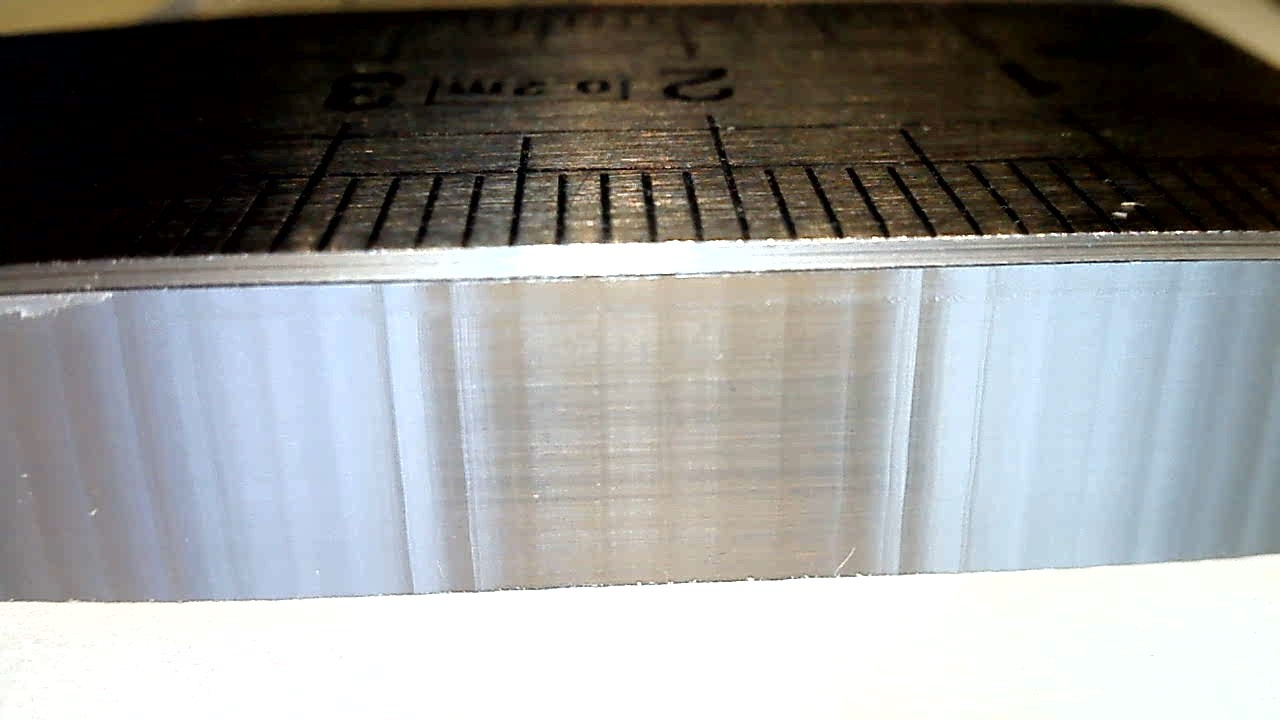
The spacing is extremely regular, and I counted 31 marks for a total length of 45mm, so each one is around 1.45mm
This 45mm segment is at angle of 1°, so at the end of that 45mm segment, the displacement in the other axis is 45mm * sin(1°) = 0.7853mm. And 0.7853mm divided by 0.025mm is…31!
Basically we’re seeing the quantization steps.
At 45° the steps are much less visible, because the machine does equal steps in X and Y at each move.
Now I just need to do the math for the mark spacing along a continuously varying tangent angle, a.k.a. a circle, and see if that is what the cut shows.
I need to sleep on it, but it could just be the stepper quantization after all.
7 Likes
Glad that seems to confirm the issue, but I expected you to take the ball screw approach!
4 Likes
Come on, it’s hard enough as it is to resist the urge! 
1 Like
I got the same texture here using laser cut not router bit , and I think this is normal with acrylic as we know that Acrylic formula ( C5O2H8)n And we generate heat while cut ! More and more heat on curves cut coz curve cut always slower than normal straight cut! so we effected the formula , and I think yes it’s normal and it’s not a machining problem !
4 Likes
Ok, now we need one of the guys that swapped for a Gecko or Massa or diy controller to contribute tests. Maybe the ability to adjust microsteps depending on material would be valuable.
3 Likes
Sounds like a job for the “Shapeoko 7”… or was it 6…or 8.
2 Likes
Fusion - 0.0004" tolerance, 0.0004" smoothing. The same steps can be seen in close ups but only 0.010" or so in length between. Full width contour cut at 0.002 chipload, 0.020 doc, no finishing pass.
My Nomad runs 1204 ballscrews with 400 steps per mm if you want some higher resolution testing.
5 Likes
Yes. Yes, I do…
3 Likes
@Omar thank you for posting this, using my laser to check for the same effect was on my list of things to try, so this kinda proves that it’s not an interaction with the material and it is a mechanical “limitation” indeed.
@neilferreri: great idea. I would ask @stutaylo to try it for us if he was not stranded in a hotel room. Maybe @patonclover can tell us whether he usually gets similar marks in curves using his Masso.
It’s funny how I never noticed earlier the effects that those 40steps/mm can have, in 99% of the cases it’s invisible, but acrylic has a way to make every tiny detail stand out.
@Microwave_Monkey: first I need to start by unboxing the (supposedly) 120fps camera I received yesterday (and did not even have a chance to try with all this acrylic excitement), and then if slow-mo cuts become popular to investigate cut quality, we’ll see about invoking the Shapeoko Seven ![]()
@Vince.Fab thanks for sharing those pics, interesting. I would expect the spacing of the marks to be variable (closer to each other when the tangent to the curve is near 45° off axis, and getting larger as the angle gets close to 0 or 90°, but on such a small piece it’s hard to tell. I would like to try and do the same cut in acrylic (would you mind sharing the file or at least the outline of that part so we can compare apples to apples ?)
Me too ! I’m afraid this will do nothing to help me control my Nomad3 lust, but I’m willing to take that risk ![]()
2 Likes
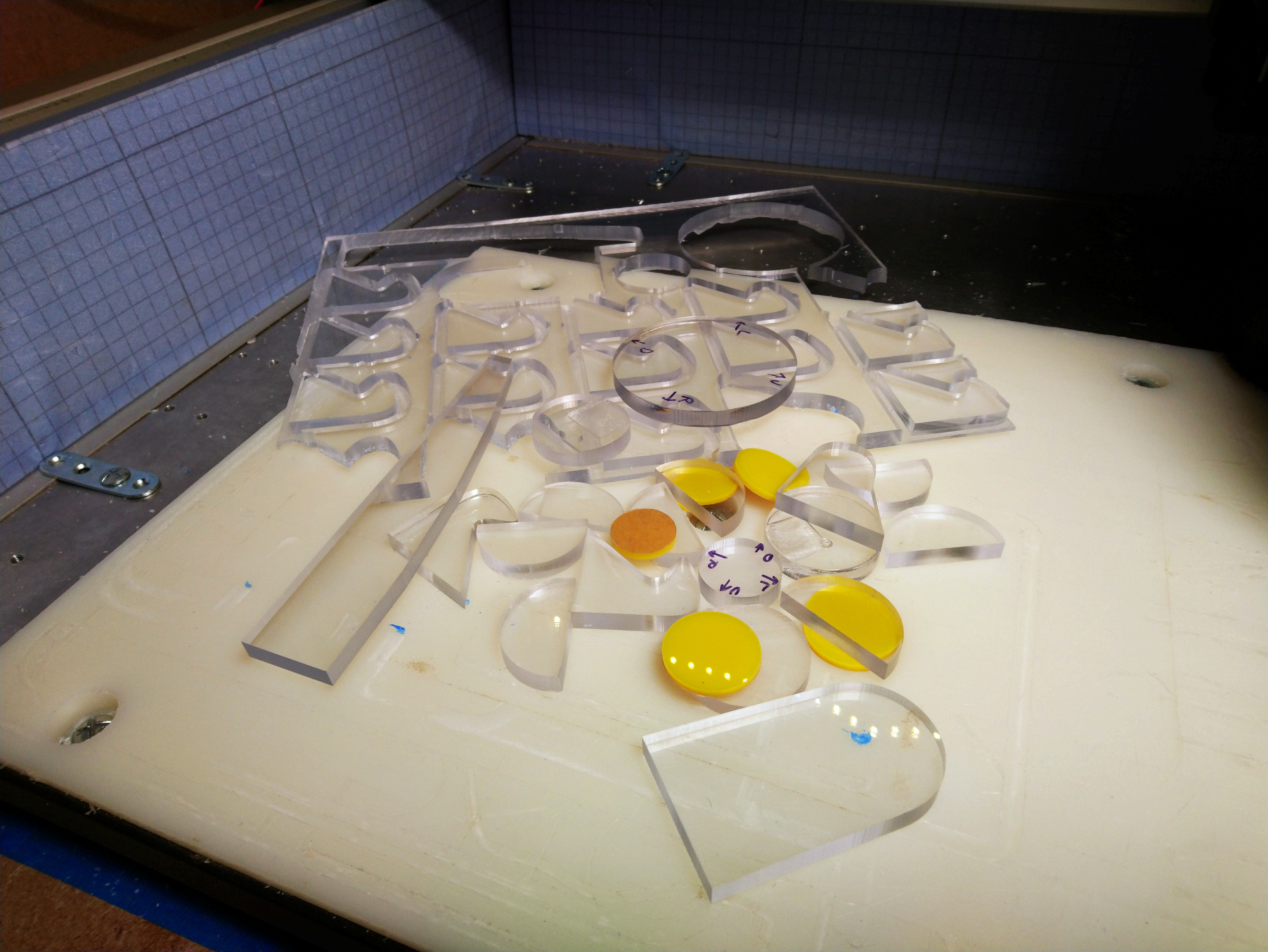
Here are what I guess will be my final tests on the matter.
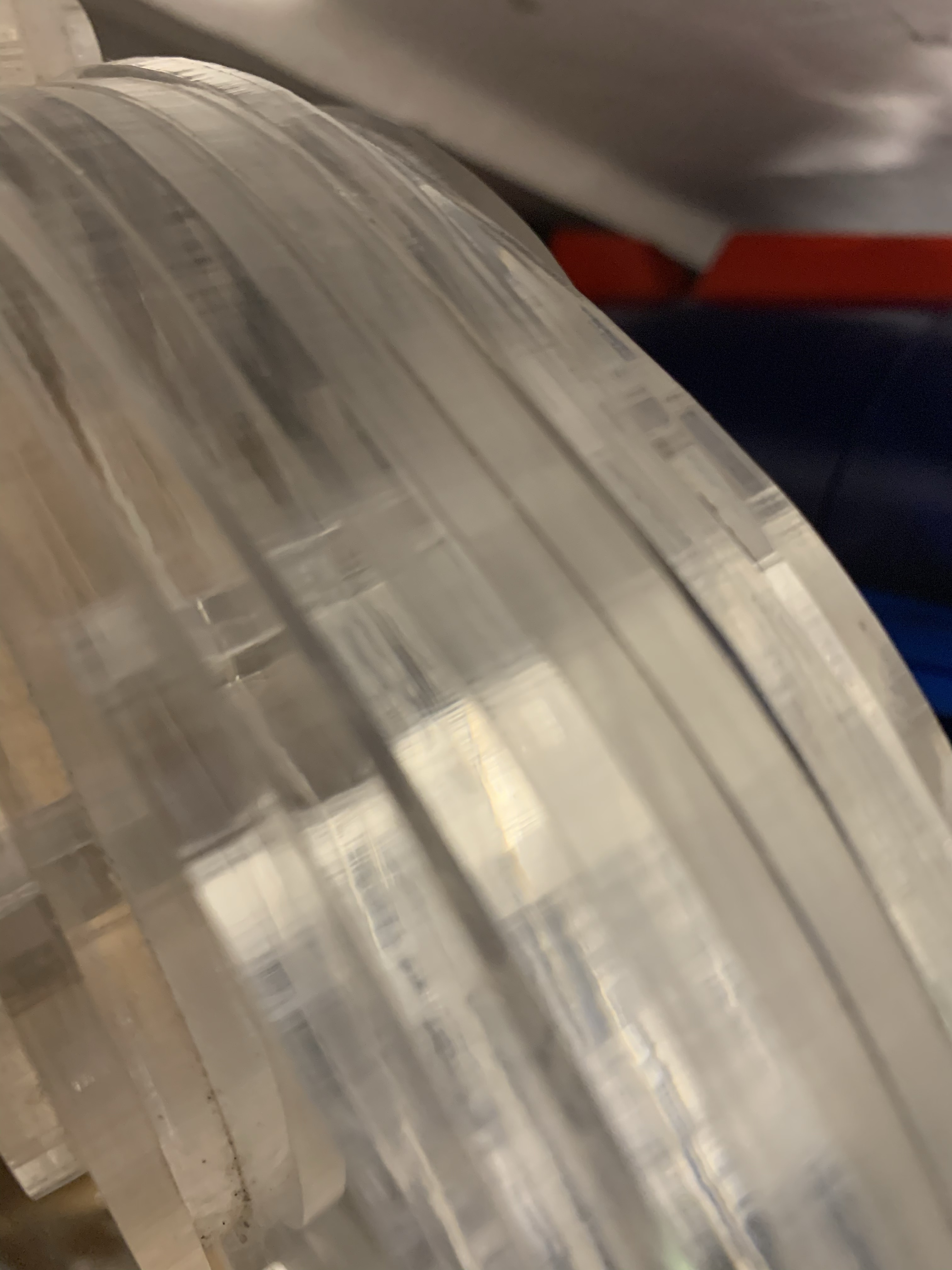
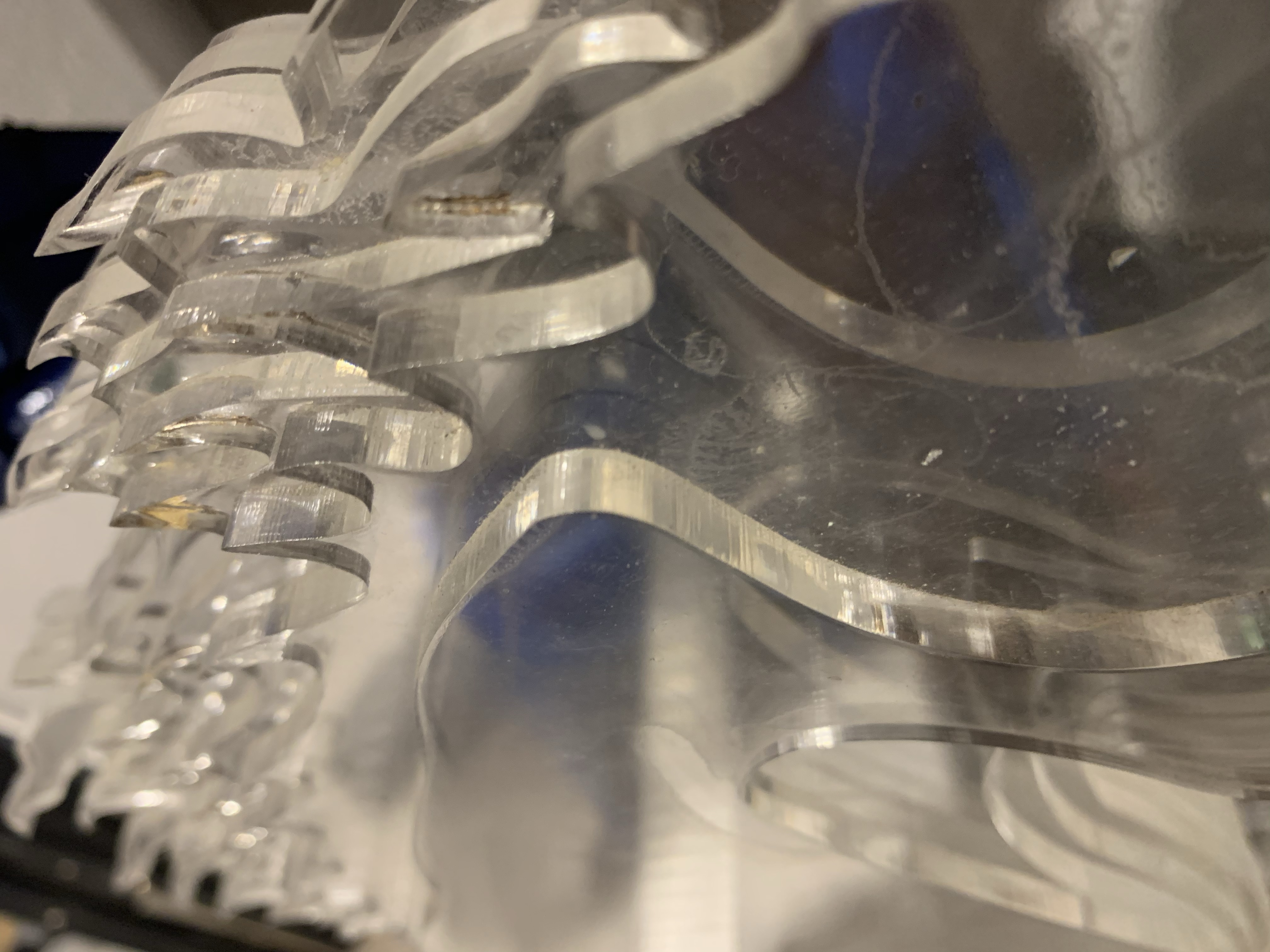
I created a test shape that has line segments at 0 degree, 5 degrees, 10 degrees, and 15 degrees from X axis.
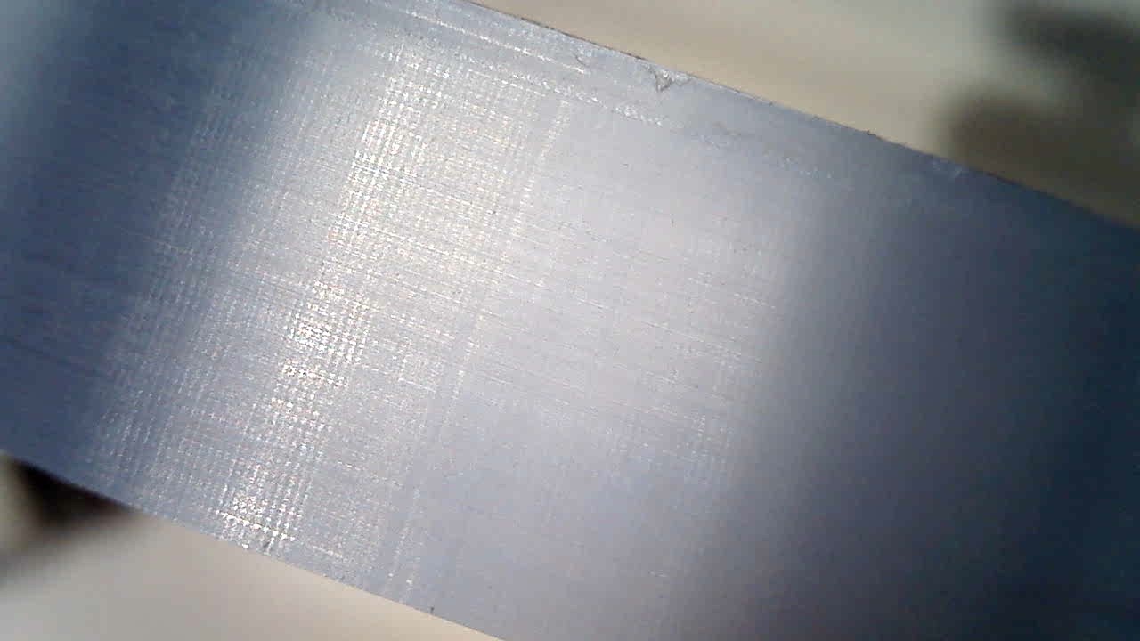
0 degree: quite smooth, and at this magnification we can the finer marks which I guess are from the tool RPM this time:
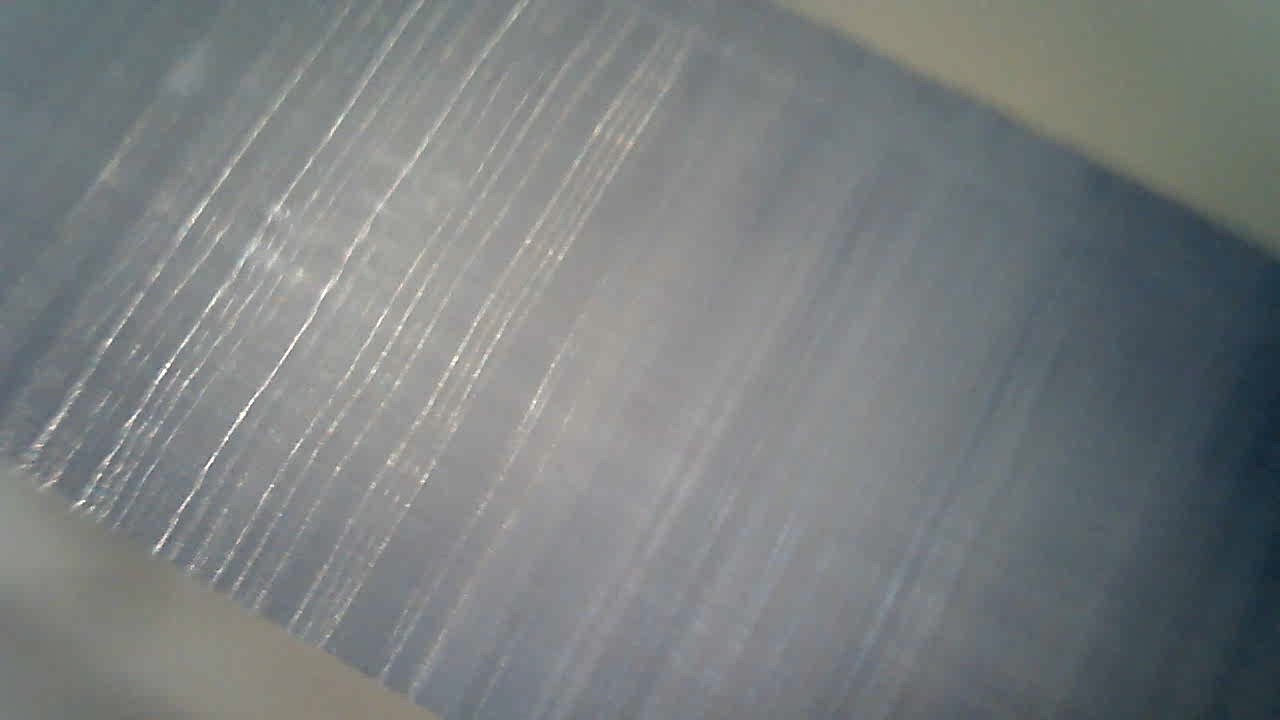
5 degrees: we see a mix of the finer “RPM” marks and larger “stepper-resolution” marks:
10 degrees: the mix of the two effects is (of course) still there, the larger marks are spaced differently:
15 degrees: same thing, the two different effects are even clearer here:
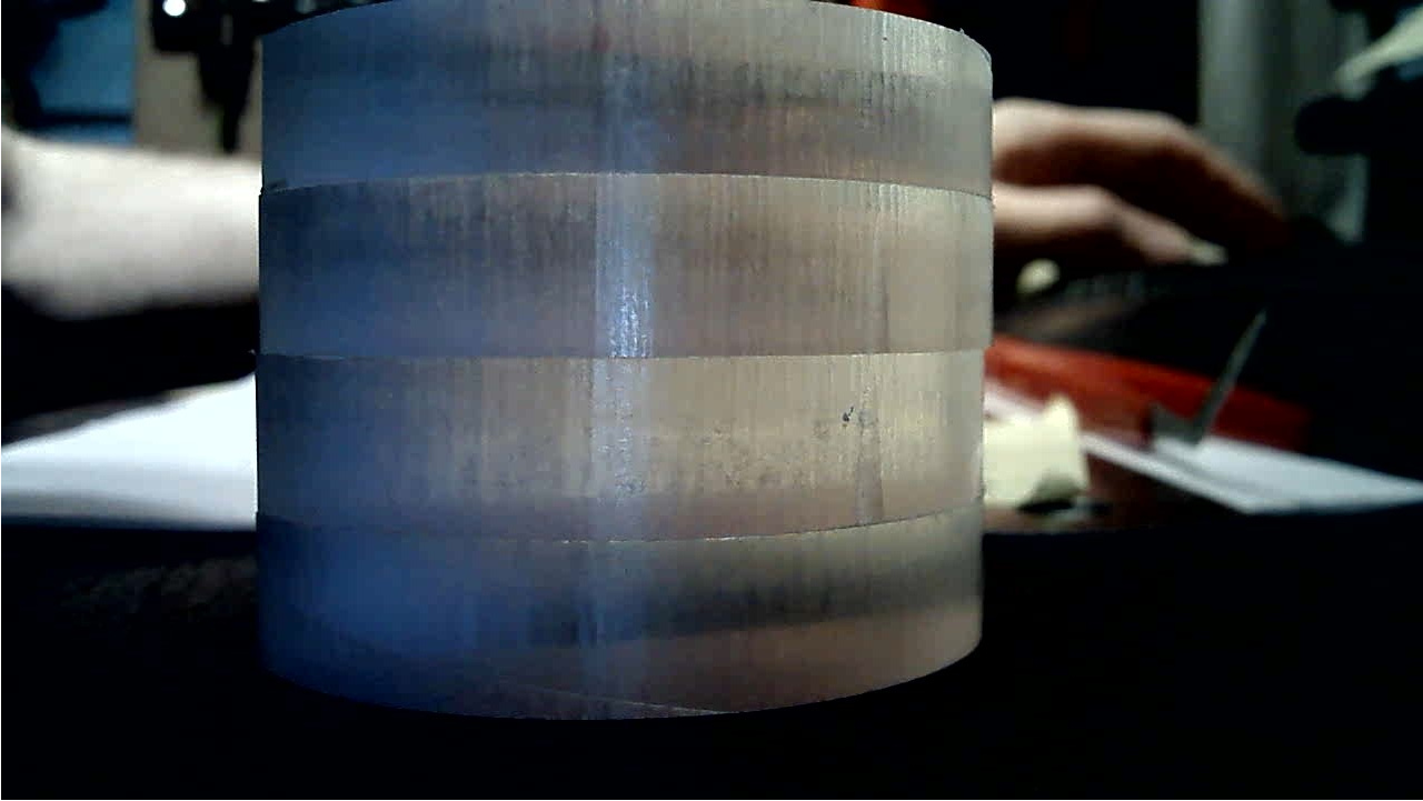
Finally I did a large (80mm diameter) circular cut, and both the high frequency and low frequency patterns are there:
Until we see close-ups of Nomad cuts from @Vince.Fab and/or cuts from someone using a finer micro-stepping value, this is it for me on this topic.
Full disclaimer: a lot of acrylic was hurt during the course of this thread
Lessons learned:
- as @neilferreri said, acrylic is unforgiving. But then again this segmented style on curves can be used to give the piece a distinct style
- I’ll make a mental note to try and stick with vertical, horizontal, and 45° lines in my acrylic pieces when possible, for the best finish
- in others cases, back to sanding & torching the edges, no big deal.
6 Likes
Thumbs up for that effort to reveal this machine limit!
So I gather that the machine travels on a grid with 1/40 mm spacing, approximating the target curve as best as it can w.r.t. to the tool diameter.
And now I wonder if the marks would probably shift for differerent tool diameters? I mean of course it would be a different path, but maybe the approximating path drops into a different pattern if you use, e.g., a 3 mm vs 1/8" bit.
Didn’t think this through, but doing multiple finishing paths could lead to smaller marks, if the individual patterns overlap?
This is the funny part: the machine is actually very, very repeatable in how well it follows the generated (segmented) toolpath. All the latest cuts above have two finishing passes around their perimeter, and it does not change much, if anything.
The best example is that 1 degree straight line: there’s only way for GRBL to go from the beginning to the end of that line, and the places where the subtle “it’s now time to do 1 microstep to the right” moves will happen will always by the same, so repeating the movement should not change much.
If one were a complete psychopath, for a perfect circle that translates to a single G2 arc command, there would be a way to overlap a multitude of overlapping arcs with slightly different starting points, i.e. change the starting point if the arc along the circle by say 1degree, run a pass, move it 1 degree further, rerun the pass, etc…rinse and repeat, until the segment/marks are blurred out all along the contour. This is purely theoretical, and of course I was not crazy enough to think of trying that (*cough *) ![]()
3 Likes
Well I don’t see any psychopath here ![]()
What I meant was something like this:
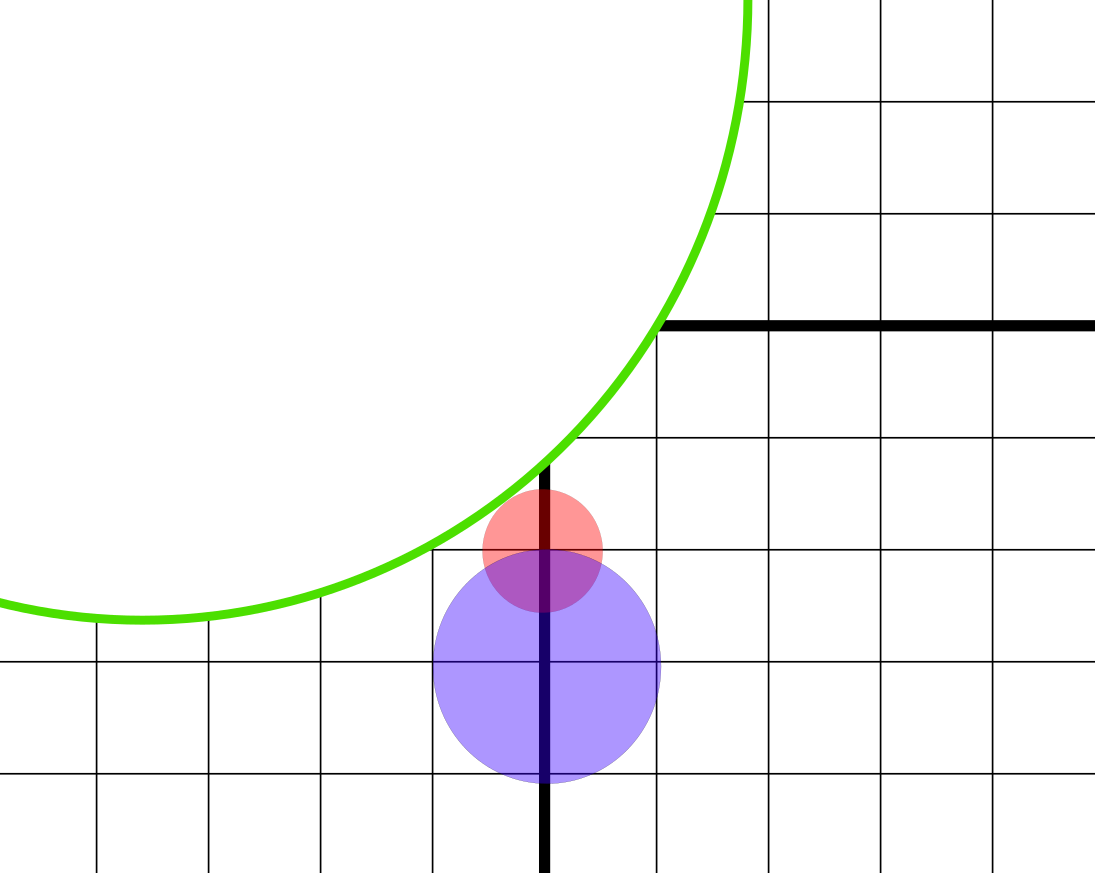
Let’s say you want to approximate the green path by moving the probes (red and blue) along the grid.
And let’s assume a very conservative approximation is done, so that you may never cross the shape with your probe.
For the given example the red probe can get closer to the shape than the blue one.
That’s why I assumed that differently sized tools may produce different marks: no need to shift arcs or something like that.
However, while writing this I realize that the fraction between the tool diameter and the grid spacing is so large that the probable shift of the marks would be extremly low ![]() and hardly noticeable.
and hardly noticeable.
3 Likes
@Julien , you just need ball screws 
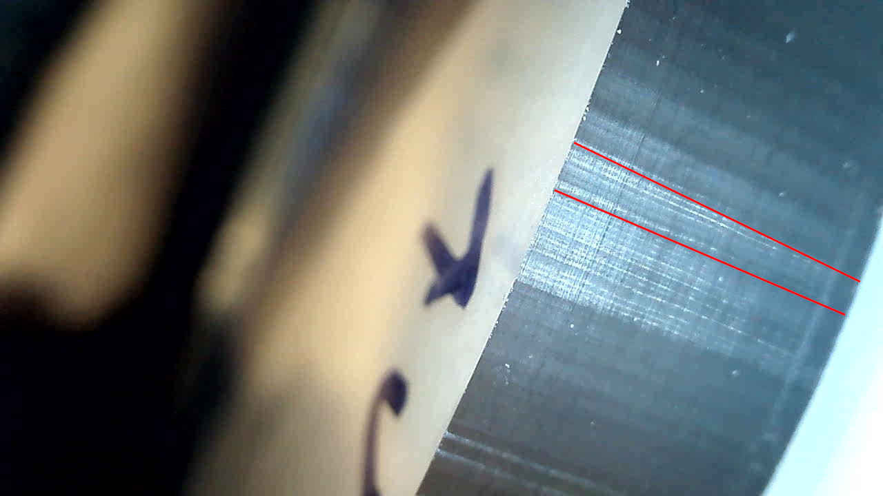
1" circles in 6061. $12 - 0.001
0.125 deep, adaptive with 0.01 left then a bore with spring pass. Left row is set to 0.001, 0.0001, 0.00001 tolerances, right row set the same but exported in mm.
Lines are very very slight but it’s still a really good finish and you’d have to look close. Honestly can’t really tell any differences between the tolerances.
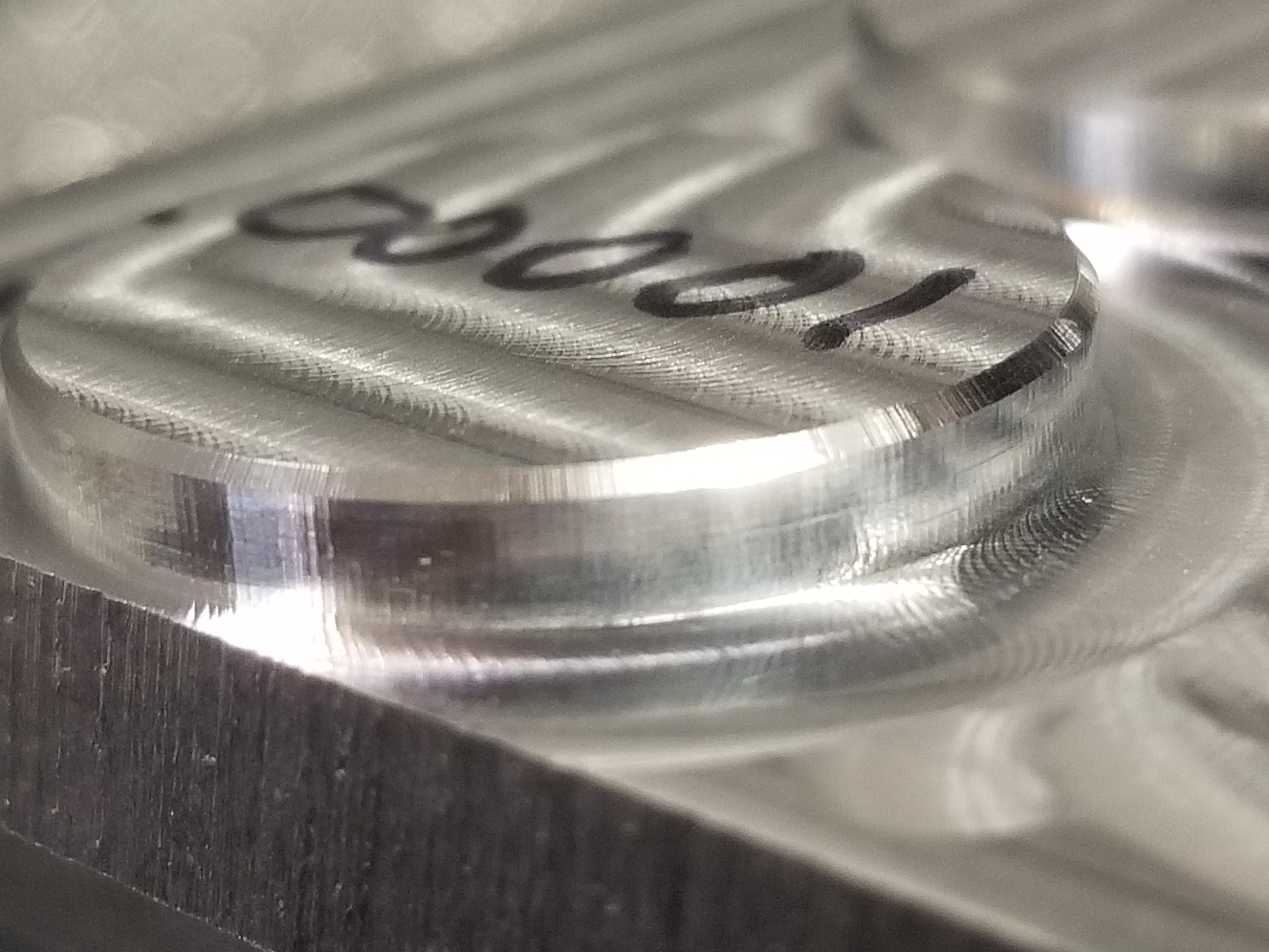
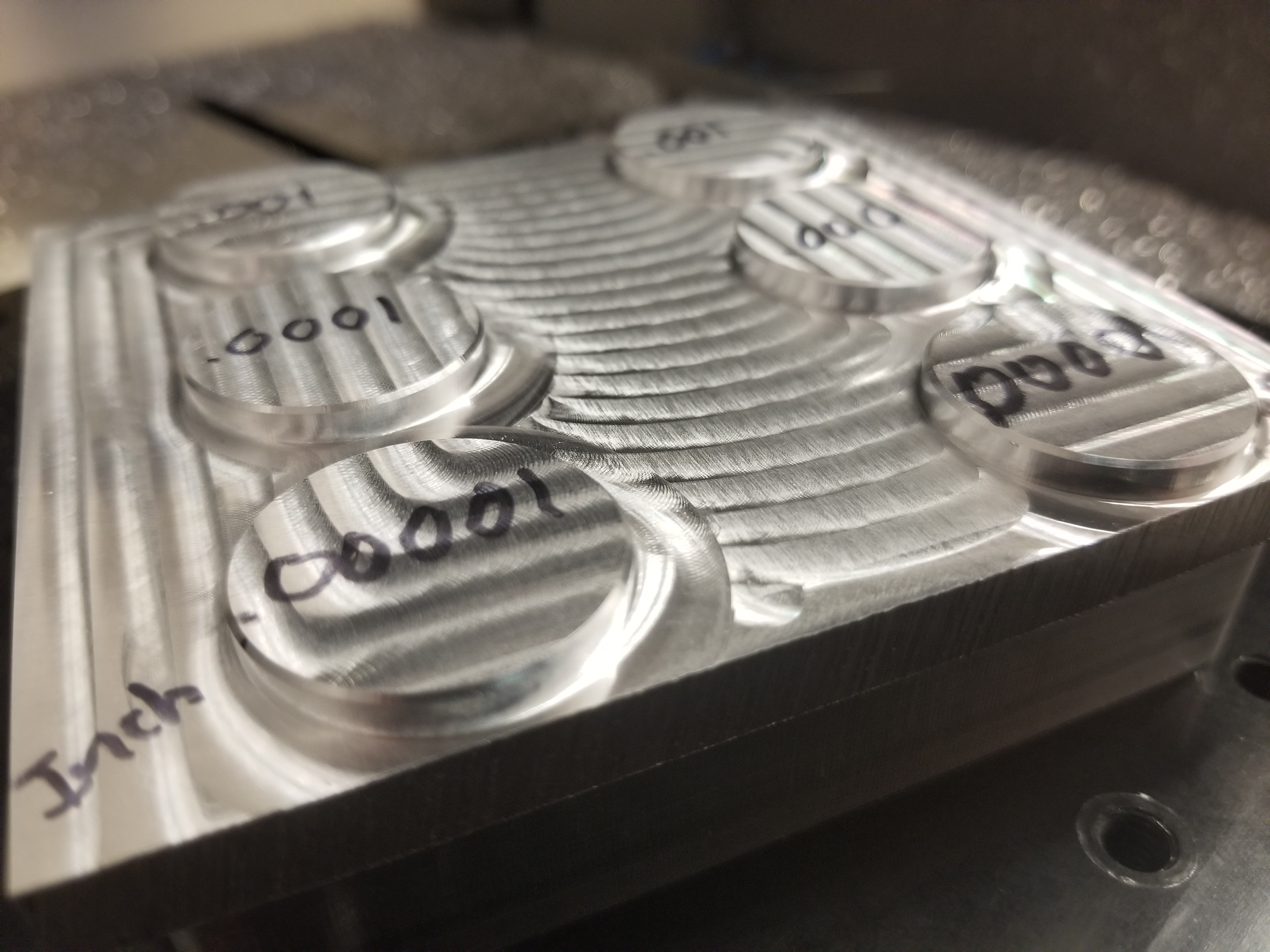
Also pita to take a good photo
3 Likes
When you output a cut file with curves, you should use a post processeor that uses ARCs. I don’t use Fusion360, but I think that V-Carve shapeoko post processeor doesn’t do arcs by default. Pretty easy to modify to add them in there.
In V-Carve curves are different then bezier curves and beziers will get output as a bunch of segments even if you save with a pp that has arcs
Try outputting a file that you KNOW uses arcs and not lots of tiny segments.
The Shapeoko post for Fusion360 does use arcs, it’s actually one of the first thinģs I checked, and the steps are there even with arcs (as they should, since it’s just the machine’ s resolution limits showing up in those cuts)
Thanks for the tests!. Nomad3 it is then 
2 Likes
Here is a YouTuber that does high-end custom PC mods and he does really great work in aluminum and acrylic. His acrylic work is especially relevant for this thread and might be worth checking out. He doesn’t spend much time explaining his set up or his speeds and feeds, but you can pick up a lot just watching. I’ve linked to part 8 of his most recent build because it is his best example of acrylic machining. He also works in acrylic in part 9 and he talks a little more about how to achieve a good finish.
Aquaceras Part 8 - Machining the pump distro plate
Edit: I may have linked to the middle of the video, but I don’t know how to fix it. If it starts in the middle, just restart from the beginning.
3 Likes