Adding ATC to my HDM

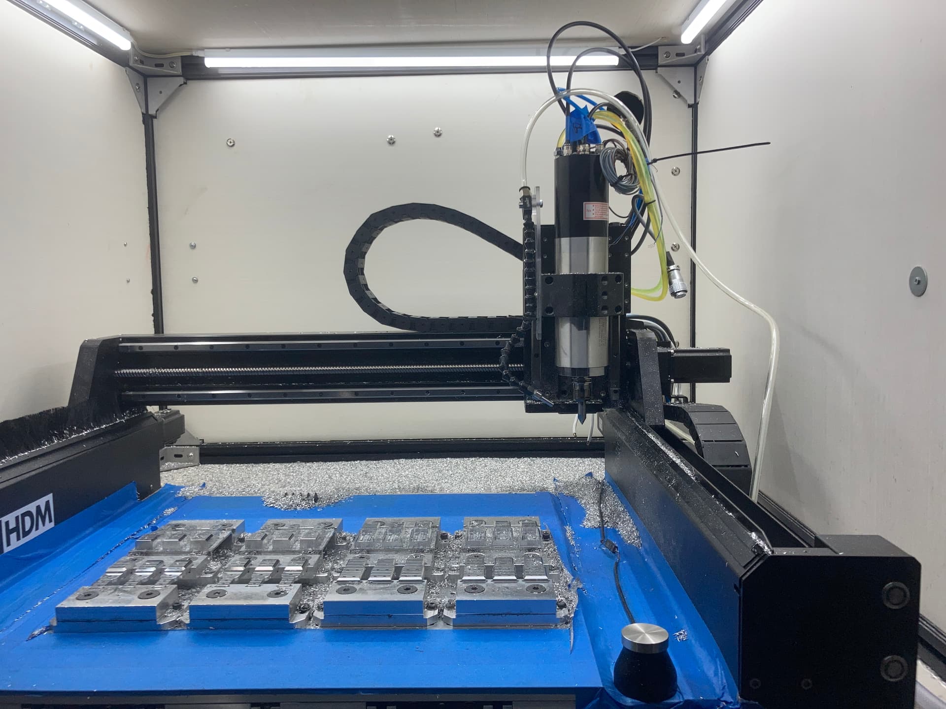
So after endless saving it’s time to start my ATC journey with my HDM.

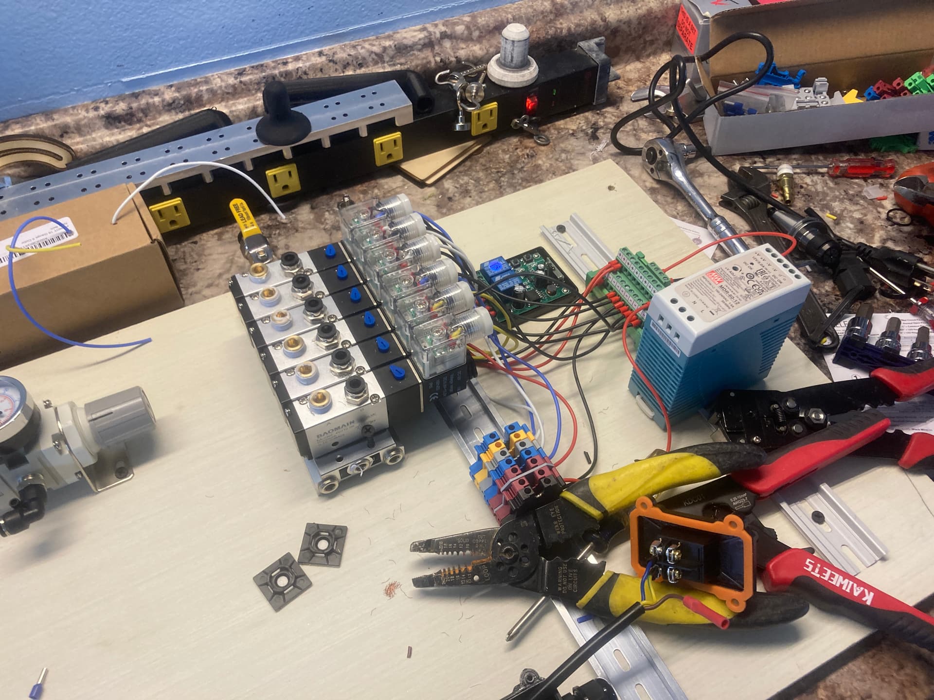
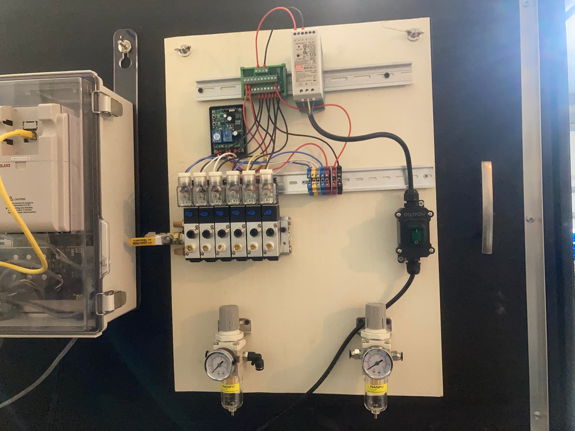
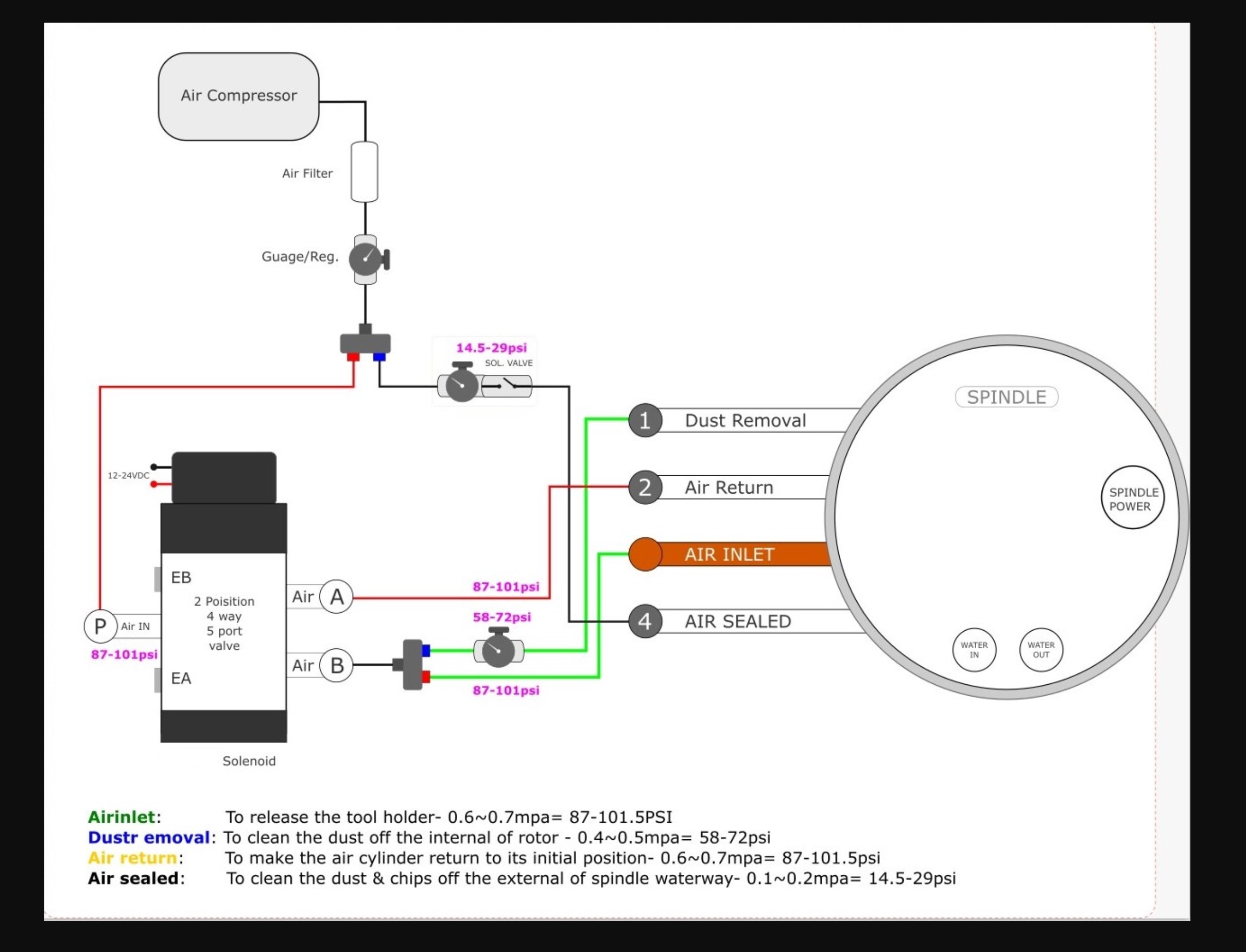
I went with the Jgl 80 2.2kw 24k spindle and I am currently working out my solenoid control for the 4 different air lines this spindle requires.

To start I will be using the stock HDM electronics with a manual tool release setup provided the stock VFD amperage can be adjusted down to 6 amps. All the other settings match the factory 2.2kw Carbide spindle. I don’t know if that setting is locked as I haven’t tried changing any VFD settings yet.

I do have a new PWNCNC 2.2kw VFD for my future Masso upgrade I can use if I have to but it’s programmed for Masso and don’t want to hook it up to the Carbide board and change it’s settings unless I have to.

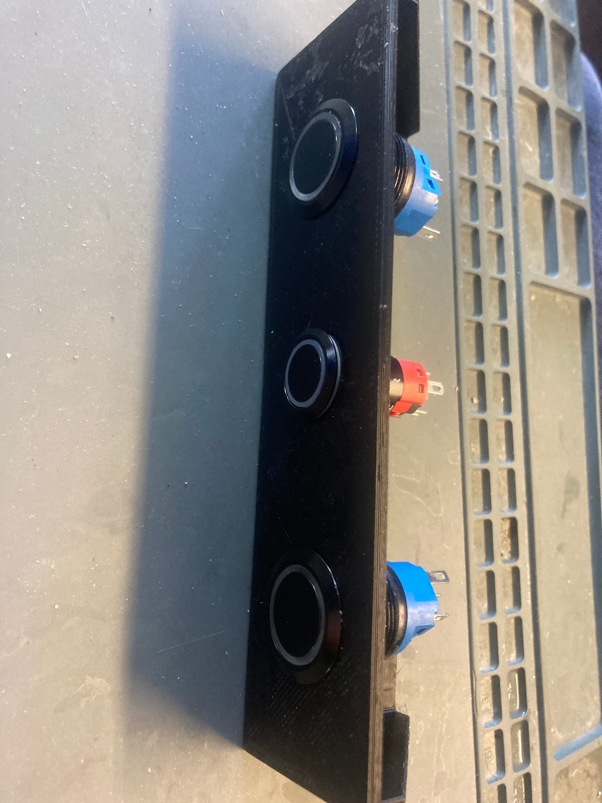
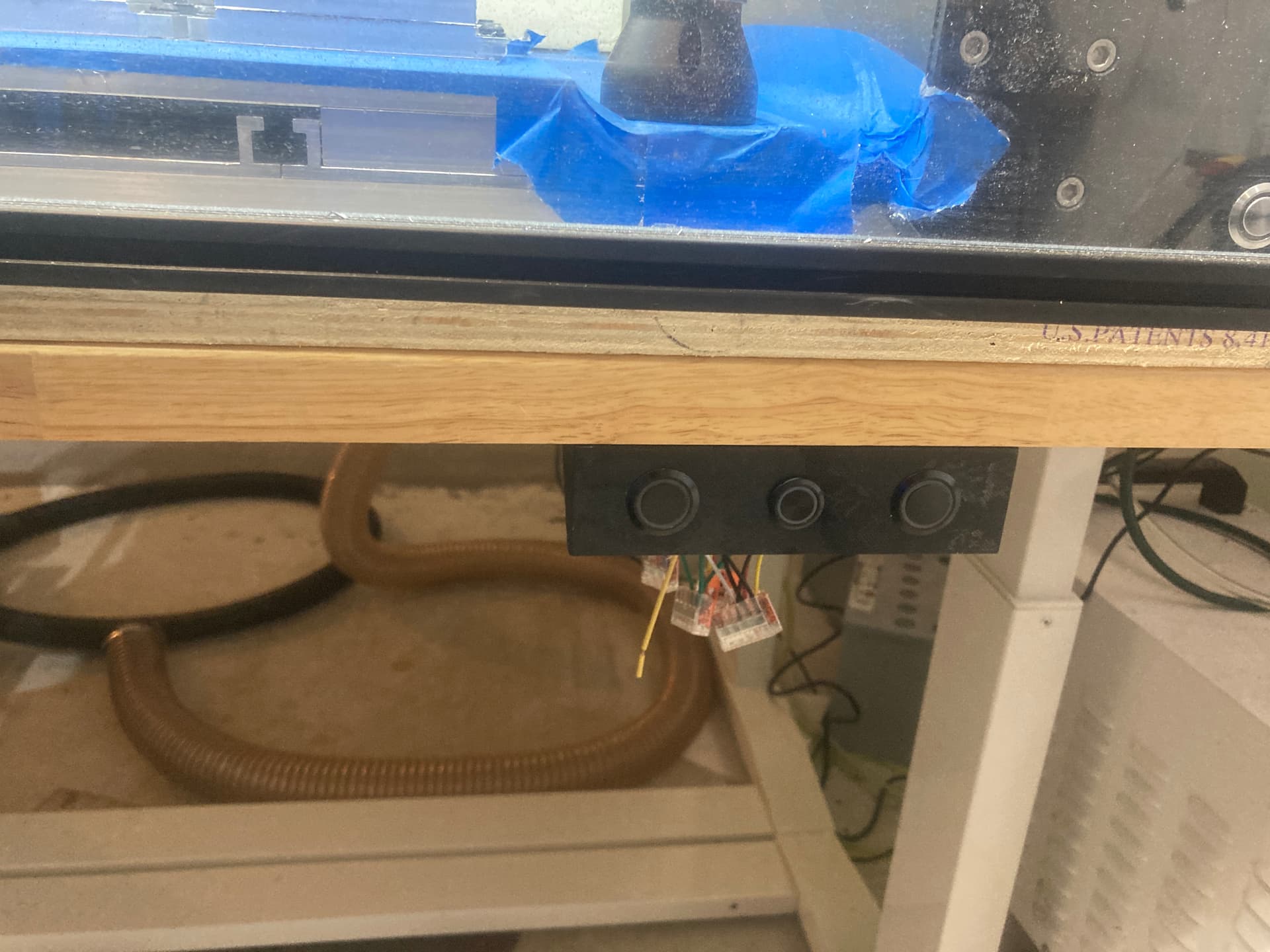
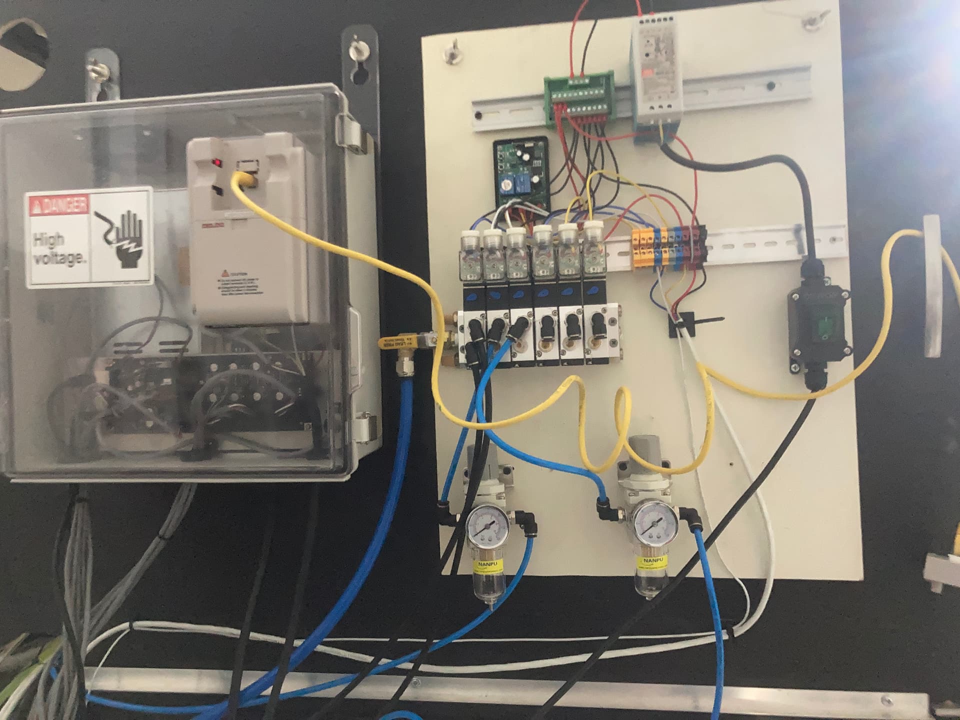
For controlling the 2 main tool change air valves I went with a 12v remote control momentary relay board and modified the remote to be sip and puff controlled. This way I can easily trigger the air release while removing and inserting various tools with my limited hand function in a safer manner.

I will be running the air valve remote control board power through the VFD relay set so the spindle must be at 0 rpm before the relay will supply power to the RF board. This way a tool release valve can’t be triggered when the spindle is rotating by mistake.

I plan to use the other pin on the VFD relay to power the dust seal air valve so when the spindle is rotating the dust seal is triggered or I will just have a latching power switch for it

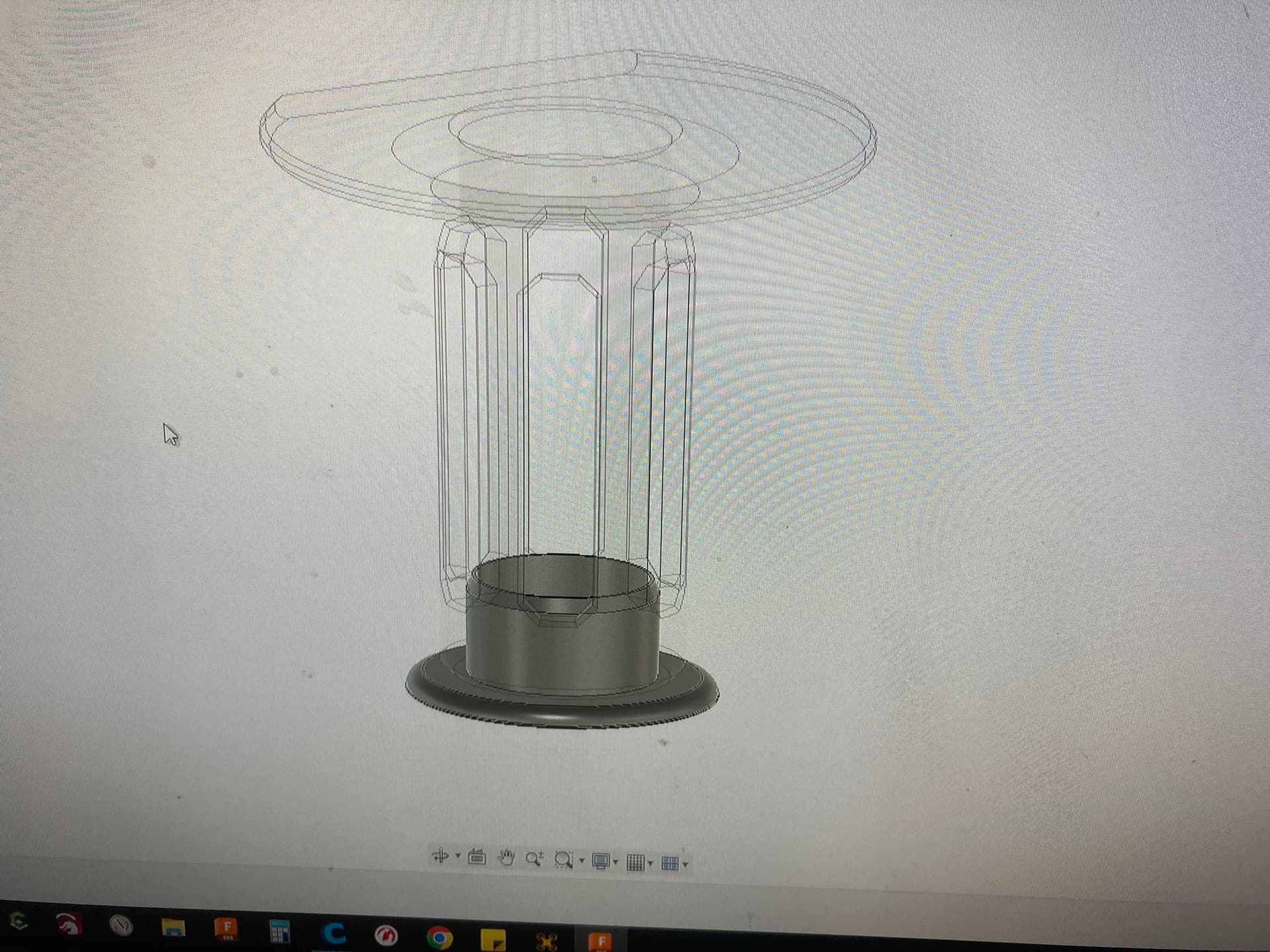
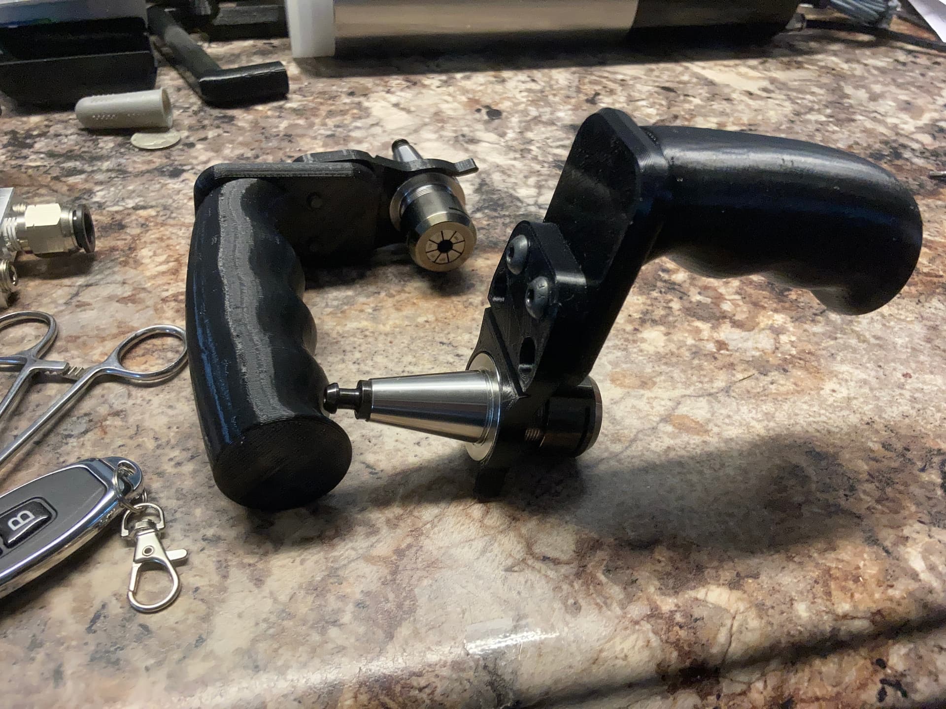
I also designed a pistol grip style ISO20 tool holder to help me swap tools and help keep me from possibly cutting myself during tool changes. The no finger function thing makes dropping and chipping tools very easy and I hope this helps reduce that. Especially with the extra weight of the tool holders I will need something to help me hang on to these spinning blades of death.


I will be bench testing the air valves this week with a small 12v battery if all goes well it will be powered by a 12v 5a Meanwell supply

14 Likes

I can not wait to see how this turns out! Lots of work but the end result will be amazing.

1 Like

Following thread. Always intresting to see how people who actually run production modify their machines.

Although it’s taking longer than I was hoping it would things are progressing.

The bench test of the wireless relay remote system worked perfect and I was able to swap tool holders with no issue. I designed and 3d printed a switch panel, and started laying out and wiring the valves.

I got a ferrule tool set and will never run bare wire strands into a screw terminal ever again. It’s so satisfying to use and makes it look great.

I will be using the latching switches to run my dust seal, Mql, and ATC lock out until the Masso upgrade.

I was able to adjust the Carbide VFD current down to 6a so I don’t need to setup the PWN VFD.

I built a proper dual shielded spindle cable and also added flyback diodes to the coils of each valve.


9 Likes

Ferrules are the only way…

Impressive progress.

For your spindle you techncially only need 2 soliniods, 3 if you want MQL. Only one of them needs to be a 5 way. The other two can be 2 way. Make sure you add flyback diodes to each.

Air seal - which you run through the the VFD relay. It needs to be on when the spindle is running.
Open and dust removal run on the same outlet with different pressure regulators
Air return on the oppsite on the other side of 5 way solinoid.

A third solinoid is useful for MQL

The below is from the MFG.

I woudn’t worry about shielded cables. It’s unliekly to make any difference on this application

8 Likes

Hmmmmmmm, hold my beer says Luke…

2 Likes

We have a bunch of machines which have ATCs, and I’m pretty sure Luke has designed multiple systems for this — the problem is, the bar for an actual released product is pretty high, and doing an ATC has multiple complexities (need for air compressor, a solenoid or vacuum to secure things, &c.) which make it hard to cross that threshold at a price-point which would make sense to a sufficient number of folks.

(Says the guy who spent a chunk of change on a quick-tool-change spindle which no one else seems inclined to: Mafell Spindle with manual tool change FM 1000 WS or PV-WS )

2 Likes

All the valves are 5 way because they were a good price for a manifold setup where I can have extra valves for future features and simply plug any unused ports easily. I did install a flyback diode on every valve.

Some future features being tool rack extend and retract automation, X rail home position air blast to remove chip build up from the rails by the homing sensor.

I have been looking at the T1 relay control parameters in the manual but I’m not sure which to use so I will run a manual button until I figure that out.

Since I had to make a new spindle cable anyway and plan on Masso swapping in the future it was best to make it double shielded. I want to do my best to follow proper cnc control wiring practices so I don’t have any EMI issues later on. I plan on sharing the process for others to use as an example so if ANYONE sees a wiring error I do not notice PLEASE SAY SOMETHING!!!

I want this build to be SAFE and something that can be duplicated so I’ve been reading and looking at builds but I am Not an expert so I am open to learn anything and everything I can.

This setup is only temporary as I am still working on the funding needed to purchase the G3 touch and Clearpath servo components I plan to run. I do admit the Clearpath servos are overkill and not needed but I want the closed loop, auto tuning, extra power, and silent running benefits. Plus they can be moved to a future chassis along with the new motion control setup so why not.

I understand why there is not a C3d ATC at least at this point in time and I’m glad the lack of one put me on the path to making my own.

The challenge of the project coupled with all the new information / lessons I’m learning during the process is making it way more valuable to me.

4 Likes

You don’t need to change any settings - I can’t recall which but one is NO the other NC - for running the air through it’s a dead easy and relaible way to do it.

As long as you don’t have any earth loops you will be fine. I’ve ran shielded cable in the past but on a handful of machines EMI coming from the cable is not an issue.

I’d not bother with clear paths - we built a HDM with servos. It was dumb - I ended up pulling it appart. 200w AC servos were just silly.

5 Likes

What did you end up doing with them? If they are sitting around and have the same specs I plan to use maybe you can sell them to me and recoup some money.

I know about the relay contacts I just didn’t know it was already setup to trigger on when the spindle starts spinning and switch off when the spindle stops.

I will have my brother check with my continuity tester to see if my VFD relay cycles with the factory settings or not when he comes back over.

There are 50+ different relay trigger settings so I didn’t want to change it until I knew exactly what setting to use…

1 Like

The ATC is up and running with the sip-n-puff wireless solenoid tool release setup. I only needed to adjust one setting on the VFD changing the current from 10a to 6a. for it to work. The spindle is surprisingly much quieter vs the stock 2.2kw in the cut with the same feeds. I was getting around 86db outside the enclosure while heavy roughing aluminum.

It was a very tedious, time consuming, and there are a few things I will be changing as mistakes were made and lessons learned but for my needs it was 100% worth it. I saved 40 minutes on a 8 tool run.

First is to swap the black 1/4" air line for the 6mm blue line as it’s slightly smaller and significantly more flexible. The 1/4" is a pain to deal with and any extra room that can be gained in the crowded cable chain is welcome.

Next up is swap out the 2 extra wires I was going to run the Z axis brake and pnp sensors with. I only had 18awg 4 conductor on hand and it’s simply way to big for what it will be powering so 22awg will be ordered for the brake and 24awg for the sensors.

I need to redesign my 3d printed tool holder grip because it just doesn’t work well for my limited function and I ended up bare hand swapping the tools and have a few stab wounds from fumbling with the loaded iso20 holders.

Think of my grip like those arcade claw machines but like the one where the owner rigged it to be even weaker. You think you got it and 1/4 to 1/2 way up it simply slips out at random times. Now you can drop a .043" bare drill and some other end mills and they have a chance of living but loaded in a iso20 holder and you can kiss it goodbye.

I’ll load a few pictures soon.


9 Likes

I had to redesign my tool holder hand grip to make one with a better center of gravity and add some protection to my mills should I drop the holder. I added a flat spot so when setting down they cant roll and a screw down base I can mount to a rack for EZ access along with cutouts so I can see what tool is in each holder.


11 Likes

Thank you for documenting your build.

This is a cool read! Good job.

This is great! I recently came across the Shapeoko HDM while researching various options and it seems almost exactly what I am looking for but my main (only?) disappointment was no ATC option so I’ll be following this build closely. Looks like we both share a love for 3M painters tape :joy:

@Luke silly/dumb just because they were an overkill or other reasons?

There were a few reasons. First, it was dangerous - it was not enclosed, and watching this thing zip around at 5-15,000mm a minute made me clench up faster than you can say pucker. Blink and you miss it. I had a full ATC on there with 9 tool changers. It should have been enclosed from day 1, but in the spirit of ‘testing,’ I had a shield, and I didn’t feel safe using the machine.

On the internet, there are many claims that desktop machines move at, say, 10,000mm a minute, but for the most part, they do not move at that speed, or acceleration is limited. When you watch an industrial CNC running servos jog about 30k mm a minute, you realize just how quickly they go. I did not intend to run any projects or even have the unit jog around that fast.

On a desktop cnc those speeds are ludicrous. You can’t machine much past 2kmm a min other than very fine surface passes. Unless you are running full production runs, you’d never save enough time to justify the time it takes to generate and test the tool paths to ensure they are reliable and safe.

Even though it could move fast - and I slowed everything way down to 5000mm a min and 500 acel, it would shake the machine, table, and everything else even when bolted to a wall. As an educated guess, you would need 3x the mass to keep it stable. I’d want extra weight - call it 500kg to be sure nothing is going to move.

I think it costs around 1k to fit out servos + additional machined parts, couplers, and wiring, extensive time tinkering and working out how to get them working right. I saw no benefit to dimension accuracy with the projects being ran. My HDM as standard hits +0.05mm pretty much the first time every time. Even if I tell myself I need +/- 0.01mm, I’m kidding myself, but I could likely tighten up that tolerance by running a little slower.

All in it was not something I would rush to do any time soon. Better ways to spend time and money.

7 Likes

Thanks for the reply @Luke however I thought you were going explain why this was a dumb idea, not make me want it more :laughing: I agree it doesn’t sound safe running at full speed but I’d look at this more like owning a sports car, most owners drive them at the speed limit but it makes them feel happy just knowing it can do 300 k/h.

I’d definitely be interested in a factory ATC option even if expensive.

Now work out how to ship these to Australia pretty please with a metric cherry on top.

2 Likes

After reading your servo reasoning I am open to other options if you have any suggestions. I am pricing out a 48v Gecko 540 setup with 600oz nema 23s as a possible option.

I might do IDS with Raptor drives because I am looking for the smoothest running performance I can get not crazy speeds. The stock drive system has a fair bit of resonance that leaves noticeable marks and groans when doing some radius turns even when air cutting. It’s the number 1 reason I was looking into servos to begin with.

I don’t know if the extra cost and setup is worth the performance gain when jumping from the 540 to Raptors but the cost of raptors and 600oz steppers is close to the same as buying servos and the drives can be moved to a larger platform should I choose to go bigger.

By any chance can the stock HDM steppers be ran at 48v? If they can I will try Raptors on the stock steppers at 48v and see how smooth I can get it to run.

I also should highlight to those who don’t know that my machine is in a decent impact resistant enclosure with heavy extrusions 3/4" plywood walls and 1/4" thick polycarbonate doors that I will be adding a latch to for extra safety.